ProECU - Nissan Leaf Tuning Guide
Introduction

| Panel |
|---|
Supplemental ContentPlatform Specific General |
Table of Contents
| Table of Contents | ||||||||
|---|---|---|---|---|---|---|---|---|
|
Programming
For information on how to program as well as flash recovery, check out.
For more software guides check out:
Specifics of leaf Programming
The Leaf has a slightly different Programming procedure to other Nissans, this is down to the way the VCM power is maintained after Key off. To program a leaf you follow the Procedure given on the ProECU programming window.
Open ProECU and detect vehicle Select the correct vehicle and programming method
Select Program VCM, and choose the ROM you want
Press the program button
wait for programming to complete
switch the ignition off and wait for 60sec (this is to wait for the VCM to shutdown fully)
then switch the ignition on
clear the DTC’s and the dash warnings
If you do not wait the 60sec’s for the VCM to shutdown the I-Key will Display a fault and start a chime, to clear this fault reprogram the ECU.
Other Useful Notes on Leaf Programming
The Li-Ion battery can be used by the VCM to charge the accessory battery so if initial programming gives an error 22 (conditions not correct) please log battery voltage to see if its being charged by the main power batteries.
Almost every map in the Leaf has a trustful equivalent which must match exactly or a DTC and limp mode will operate. If you change a map ensure that its trustful copy is matching.
If you get an I-Key error after programming you can usually fix it by programming again using the correct ignition sequence, this should clear the fault and allow the car to start normally.
ROM Dumps
If you have a previously unidentified ROM in a vehicle a ROM dump will be required for support to be added. when trying to dump a ROM this message will appear.
To make a ROM dump a password will be required from EcuTek support so please contact support@ecutek.com. EcuTek support will then be able to guide you through the process for dumping the ROM and submitting it for support.
Accelerator
The leaf employs Accel pedal output scaling as well as accel pedal movement smoothing, you can adjust the output pedal progression using the Powertrain Torque Accel Multiplier maps, there are 9 different maps used under different circumstances (each with their own trustful map which must match exactly).
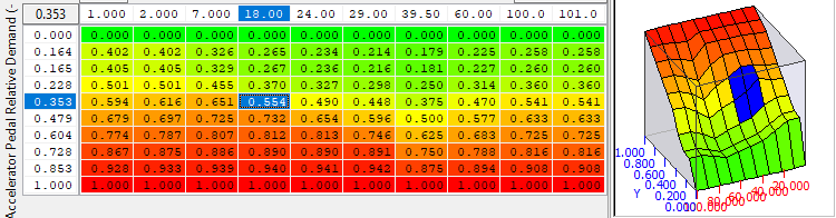
There are also 4 separate accel pedal smoothing maps which alter the speed of change of the accel gradient based on pedal position. These can be adjust the response of accel request coming from the pedal maps.

| Column |
|---|
Map List  |
| Column |
|---|
|
| Column |
|---|
Live Data Parameters  |
Water Pump Control
The Leaf uses an electric water pump (some models have 2 pumps but this was deleted in 2013) that feeds coolant by pressure through the high voltage control (inverter) and traction motor. The coolant flow rate is set with either 1D, 2D or 3D values depending on what triggers the cooling request.
The VCM controls the electric water pump to achieve the flow rate corresponding to water temperature and vehicle speed. The electric water pump has a feedback function that when a malfunction occurs the electric water pump transmits an error signal to VCM and prevents the reduction in coolant flow rate.
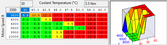
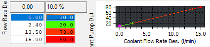
The PDM (Power Delivery Module) is also cooled during charge, during this operation mode the VCM activates the electric water pump to circulate coolant to PDM (Power Delivery Module) at different flow rates. the flow rate commanded is then converted into a duty cycle to output to the pump controller, this map can be altered to ensure the pump duty matches the actual flow rate of the motor.
| Column |
|---|
Map List 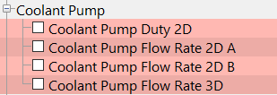 |
| Column |
|---|
|
| Column |
|---|
Live Data Parameters  |
Radiator Fan Control
The VCM calculates an appropriate speed according to coolant temperature, vehicle speed, and a cooling fan
speed request signal received from A/C auto amplifier and transmits a duty signal to the cooling fan control
module. The VCM judges a maximum fan speed according to a cooling fan speed (calculated from coolant temperature
and a vehicle speed) and that requested from the A/C auto amplifier and outputs drive duty.
NOTE: The cooling fan may be activated during charge or deice system operation (only models with heat pump) even
when the power switch is OFF.
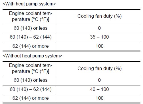
It is believe that the duty of the fan when moving is set by the 3D rad Fan Coolant Fan Duty maps
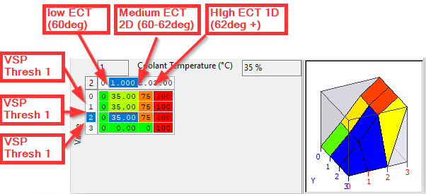
the X (horizontal) Axis of this map are the outputs of Rad Fan Coolant Temp Threshold maps (2D) threshold 1D values
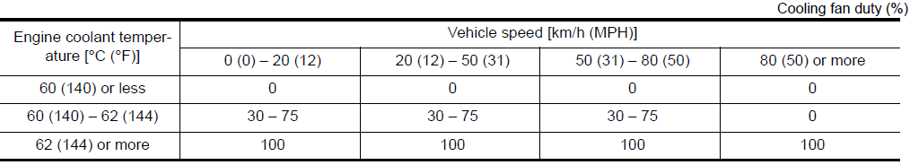
the Y Axis (vertical) of this map are the Vehicle speed 1D values . the OEM setpoints are as described below.
With Heat pump
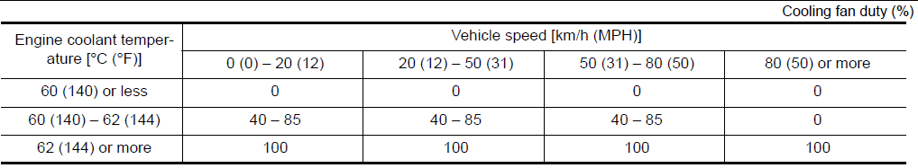
Without Heat pump
it will also set the fan control up during de icing and preset climate control modes using the alterantive maps the OEM setpoints for Cooling fan operation by climate control are
| Column |
|---|
Map List 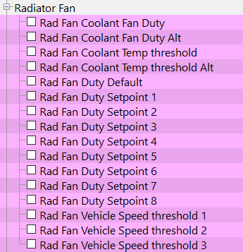 |
| Column |
|---|
|
| Column |
|---|
Live Data Parameters 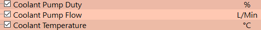  |
Diagnostic Trouble Codes
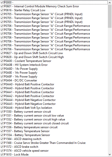
DTC’s on the leaf are in checkbox format, these can be used to allow torque requests outside of the inverters maximum achievable amount
| Column |
|---|
Map list  |
| Column |
|---|
|
| Column |
|---|
Live Data Parameters |
Sensor Scaling
the leaf VCM has many sensor inputs,
12V Battery current sensor
12V Battery Temperature Sensor
Refrigerant Pressure Sensor
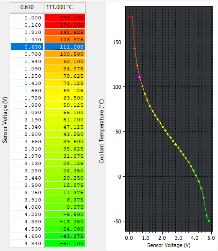
Coolant Temperature Sensor
Accel Pedal Position Sensors 1 & 2
Cruise and Eco button Voltage input
Some of these use 2D maps and other have 1D multipliers and offsets, we have added the major 2D maps for coolant and battery temperature that can be adjusted if alternative sensors are swapped.
| Column |
|---|
Map list 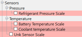 |
| Column |
|---|
|
| Column |
|---|
Live Data Parameters  |
Limiters
there are many toque limits from many different functions, some of which have an unknown origin. It was found during testing that the torque limit 1D’s and the motor torque limits 2D maps needed to be lifted to allow increased torque demand over stock.
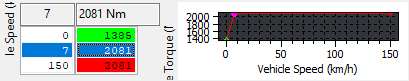
These must be raised in conjunction with the other Main motor torque and axel torque targets and limits.

| Column |
|---|
Map list 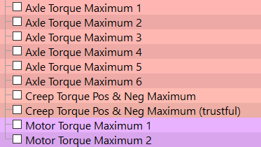 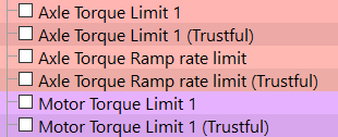 |
| Column |
|---|
|
| Column |
|---|
Live Data Parameters   |
Inverter Torque & Power
While the VCM can request a set amount of torque, the inverter is allowed final control over the final delivered torque values. this is why currently (without programming access to the inverter controller) or after market inverter controllers you can request as much torque as you want but the inverter will only deliver as much as its allowed to.
OEM Inverter needs to be swapped or reprogrammed to allow higher torque and power outputs
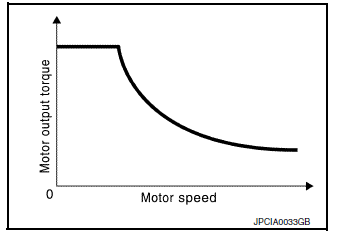
Gen 2 Motor / Inverter Specs
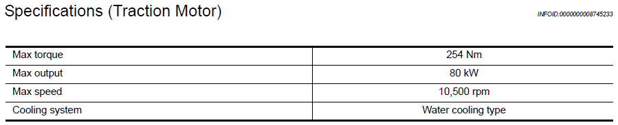
If the inverter from a Gen3 Leaf (with higher torque and rpm limits) is placed on the Gen2 traction motor the EV CAN messaging appears to be the same so should work without further CAN bridging, The VCM will then need to be tuned to request more torque from the new Inverter and increase the power and torque.

| Column |
|---|
Map list |
| Column |
|---|
 |
| Column |
|---|
Live Data Parameters 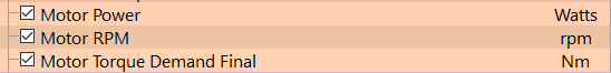 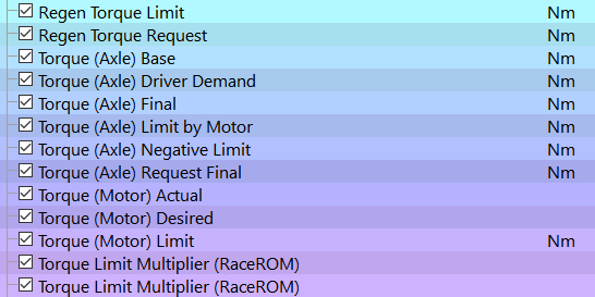 |
Torque
Torque request for the leaf is set primarily in tractive force (force the wheels apply to the ground) and these values are converted and limited at various point to derive a final motor torque demand. The basics of how the maps work together are shown below
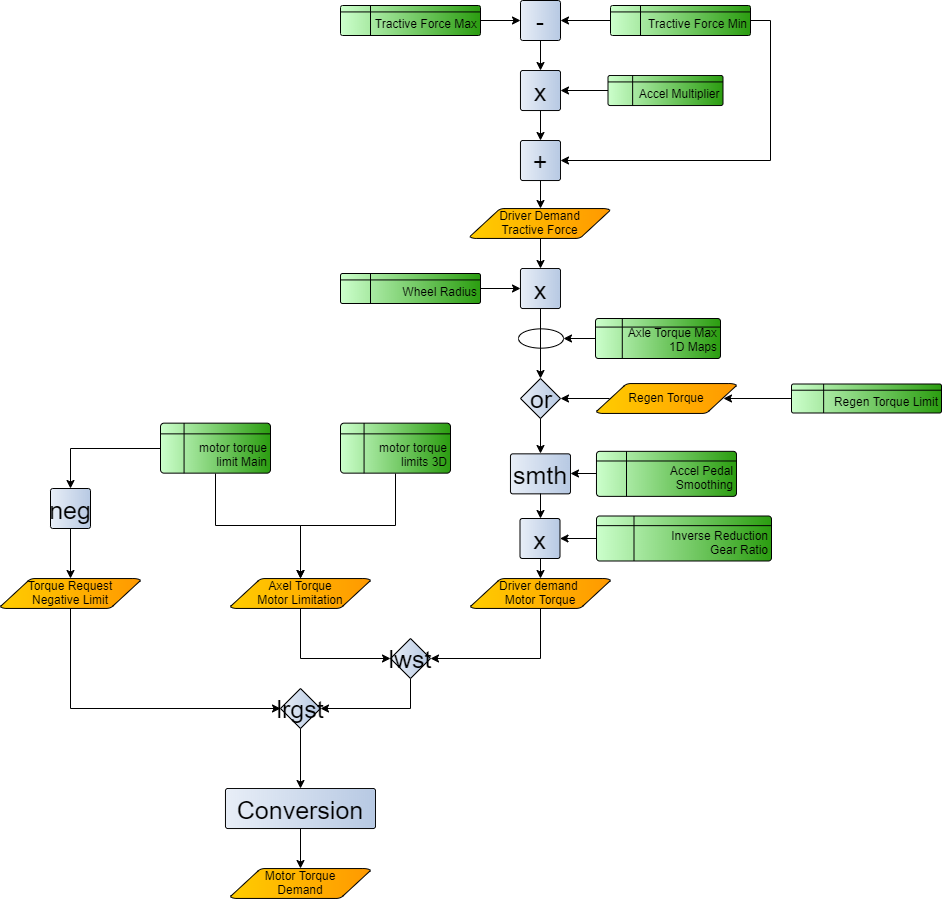
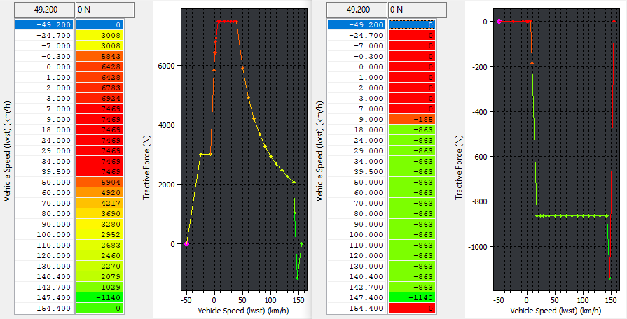
To Increase/modify the targeted torque from the VCM (wont increase the torque delivered by the Inverter) the first maps to change are the desired tractive force maps. These maps are the maximum and minimum values for tractive force that the driver can desire, these two maps are used to generate the max available demand which is then multiplied by the accel pedal scaling maps and then the minimum map is added back determine the final torque request values.
these values are then converted from tractive force to Motor Torque using wheel size and the reduction ratio
Wheel Radius

Reduction Ratio

| Column |
|---|
Map list 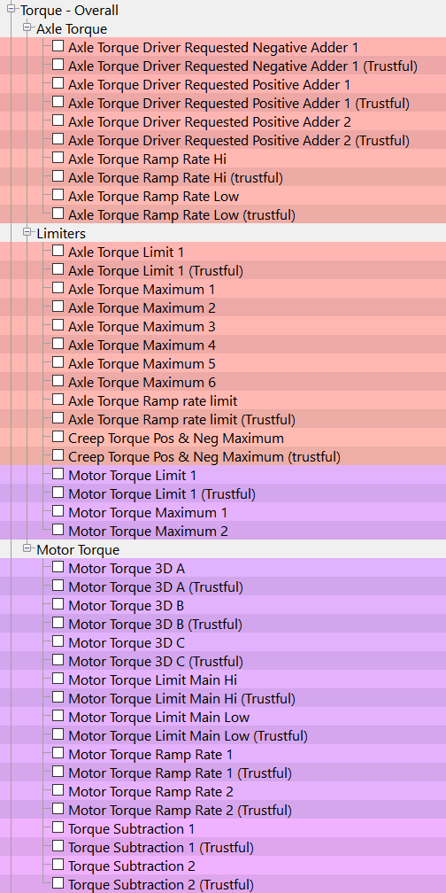 |
| Column |
|---|
|
| Column |
|---|
Live Data Parameters 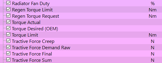  |
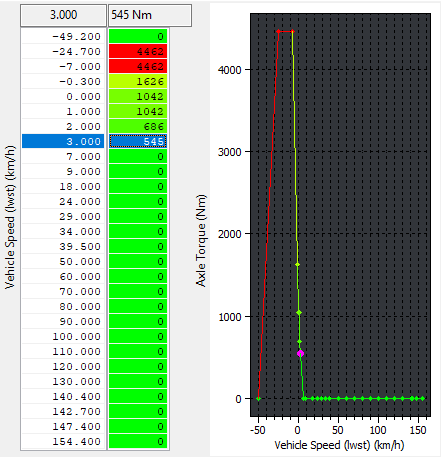
Creep Torque
when the Leaf is stationary small amounts of torque are applied when the vehicle is in drive. This torque henceforth called Creep Torque can be calibrated. There are creep torque limits and targets in both tractive force and axel torque. They are calibrated to prevent rolling backwards by applying higher tractive force demand at negative vehicle speeds.
| Column |
|---|
Map List 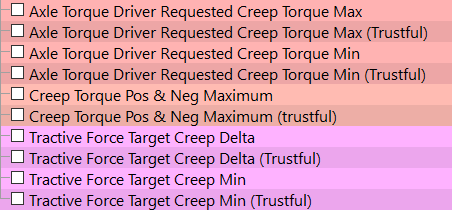 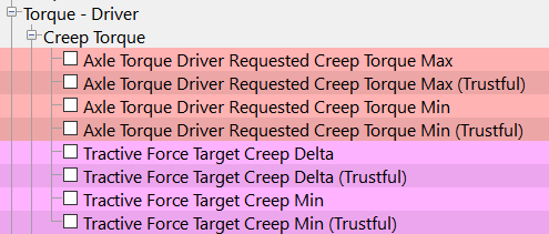 |
| Column |
|---|
|
| Column |
|---|
Live Data Parameters |
Regen Torque
Regen torque is determined by the ABS controller (proportion of braking force) and the amount of braking is split between the motor inverter and the hydraulic braking system in the VCM. Sewe the below Diagram for a more in-depth diagram.
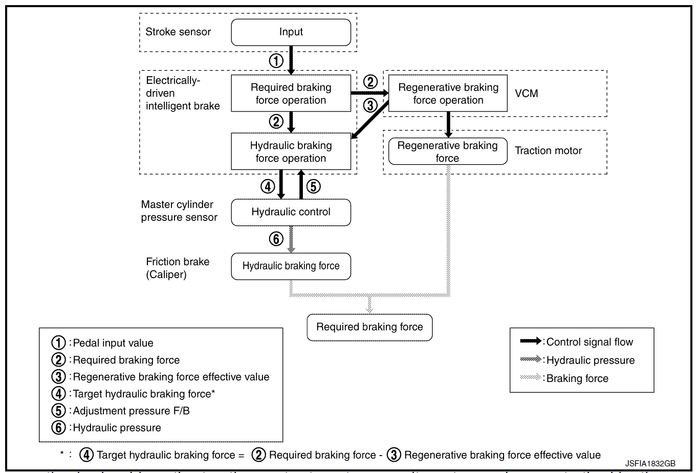
there is a limit map that sets the amount of regenerative braking force that the VCM can command this map is
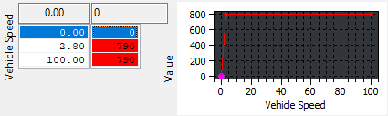
If HV battery charge levels are high enough the VCM reduces or stops the regen charge control.
| Column |
|---|
Map List 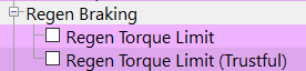 |
| Column |
|---|
|
| Column |
|---|
Live Data Parameters  |
Misc.
Eco Mode / Mode B
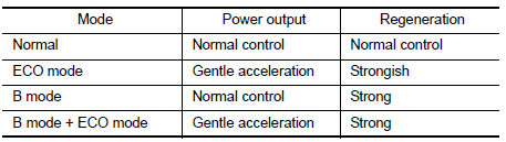
Eco Mode is triggered by the steering wheel button for eco mode and uses the second set of eco mode torque maps until the kickdown switch is exceeded. Once the driver depresses the pedal further than the kickdown switch point the VCM swaps over to the normal running mode maps to guarantee adequate acceleration.
Mode B is a high Regen energy mode where when selected Allows the inverter to take more of the braking force with the traction motor and increase regen battery charging.
| Column |
|---|
Map list 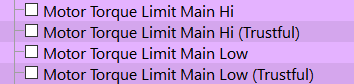 |
| Column |
|---|
|
| Column |
|---|
Live Data Parameters 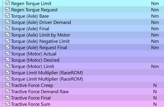 |
RaceROM Torque Control
RaceROM torque control is a limiter employed to limit the requested motor in acceleration and braking (regen) modes. this is done by multiplying the torque limit maps on both positive and regen torque functions. This is done using slider torque scaling allowing you pre-set the torque scaling multiplier per map switch mode for both max Driver requested motor torque and also maximum regen torque.
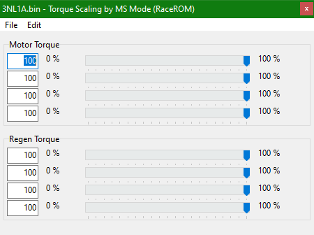
These pre-sets can then be adjusted by the driver using ECU connect,
| Column |
|---|
Map list  |
| Column |
|---|
|
| Column |
|---|
Live Data Parameters |
RaceROM Map Switching.
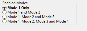
To allow for driver adjustable max driving and regen torque map switching using ECU Connect has been integrated into RaceROM. It is set up by choosing the desired options and addint the map switch description into the modes required.
| Column |
|---|
map list 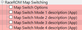 |
| Column |
|---|
|
| Column |
|---|
Live Data Parameters  |
| Warning |
|---|
EcuTek ProECU tuning tools tools should only be used by experienced tuners who understand the product and engine calibration.
Retail customers ** If you have any doubt that you do NOT have the experienced required to use this product then you should NOT USE IT, you should simply contact your EcuTek Master Tuner shown clearly on the top of your Programming Kit or visit your preferred tuning shop to have a professional tuner to use it for you ** |