BRZ/FRS/GT86 RaceROM Speed Density Setup
![]()
BRZ/FRS/GT86 RaceROM Supplement: Speed Density Setup
How to Setup Speed Density (SD)
EcuTek RaceROM Feature Files (RRFF) offer a Speed Density tuning option for trade customers, or Retail customers that have purchased the optional RaceROM BRZ upgrade package. This is a MAP sensor based load input into the ECU (compared to the more forgiving factory MAF sensor based load input). In certain situations Speed Density is more suitable over a MAF based input, these are usually: In these situations the Speed Density or Hybrid Speed Density can be used.
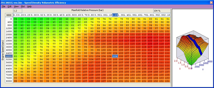
The SD VE map is against Engine Speed (RPM) and Manifold Pressure (Bar). The values in the map are volumetric efficiency (VE) %.
The older RRFF SD Map had Mass Airflow values in the SD map, but the latest RRFF now uses a superior VE based SD calculation which we will cover here.
When the SD map is active, it simply replaces the current Mass Airflow (g/sec) reading that would normally come from the MAF sensor, therefore ALL load calculations are not affected by the MAF sensor at all.
When the SD map is correctly calibrated, there is little difference from running on MAF and the SD VE map works like this:
- INCREASING the SD values will make Engine Load higher, therefore retarding the Ignition and increasing the Injection volume amount will make the AFR richer
- REDUCING the SD values will make Engine Load lower, therefore advancing the Ignition and reducing the Injection volume amount will make the AFR leaner
If SD is used, ensure that the MAP sensor can read to the pressure you are running!! (Any pressure over 1.37bar absolute will need a 3bar MAP sensor fitting etc)
As a VE based calculation it is seriously affected by any fundamental change in VE like fitting a Supercharger, Turbocharger, changes in the VVT angles or the VVT not actually working.
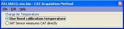
Charge Air Temp (CAT) also plays a critical part in the VE calculation. As a Charge Air Temp sensor is NOT fitted by the factory, we have to assume a fixed temperature and then make a calibrated compensation based against Intake Air Temp.
No air temp sensor fitted in the charge pipe

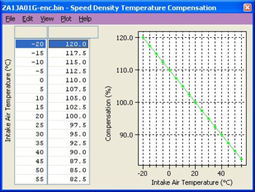
The Speed Density Temp Compensation map will adjust the SD VE calculation based on the current IAT, therefore attempting to calculate the true air density by calibration.
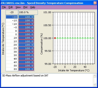
Intake Air temp sensor fitted in the charge pipe
If the Air Intake Temp sensor (AIT) has been placed in the charge pipe and the IAT is measuring true CAT (after the turbo/supercharger and intercooler) then we do NOT need to use the ‘Speed Density Temp Compensation’ map (as VE calculation is including true CAT). In this situation, we need to select the CAT Acquisition Method of ‘IAT sensor measures the CAT directly’ option.
We also need to set the values in the ‘Speed Density Temp Compensation’ to 100 as we are not ‘guessing’ the CAT anymore.

Hybrid SD Mode Options
RaceROM's powerful Hybrid Speed Density allows the load input to be switched between MAF and SD as required going either from MAF to SD or vice versa. The condition to switch between the two can be one or multiple of the following
Engine Speed (RPM)
MAP (bar)
Mass Airflow (g/sec)
If you wish to ahve the engine running on MAF at idle and low load and then continue on MAF until 5000rpm switching at SD beyond that, you would simply set the RPM threshold with a 5000rpm activation and 4950rpm deactivation

In addition you can specify that the boost pressure has to be over a certain pressure before the switch to SD as well (like over 5000rpm and over 1.5bar boost absolute or 7.5psi boost if you prefer), this is the Hybrid mode.
The base SD VE calibration has been made against a stock naturally aspirated engine (NA) with stock cam timing. We have also developed a SD VE map to suit the Vortech Supercharger setup.
NOTE : If running full time SD or Hybrid SD we recommend the P0103 DTC is disabled, this 5 volt MAF protection DTC will force the ECU to use the 1d value called ‘MAF Failsafe Load Calculation Multiplier‘ which will change the Engine Load (even if full time SD).
** If using Hybrid SD then ensure you use RRFF version 8 or newer, older versions can cause a hesitation when switching from MAF to SD.
The next section shows a Hybrid SD transition log file and includes the SD Volumetric Efficiency (%) in the log file. SD VE can still be ‘calculated’ even if the ECU is currently running on MAF.
See the log file below that shows the transition from MAF to Speed Density at 4750 RPM.
So below 4750rpm the ECU is running MAF.
Over 4750rpm the ECU is running SD, but the MAF reading can still be logged even though the ECU is not using the MAF reading – Yellow Line.
See the Mass Airflow (Blue Line) and MAF Sensor reading (Yellow Line) are the same below 4750rpm.
Over 4750rpm the Blue and Yellow line separate as the Mass Airflow is calculated from the SD map and not the MAF sensor reading.
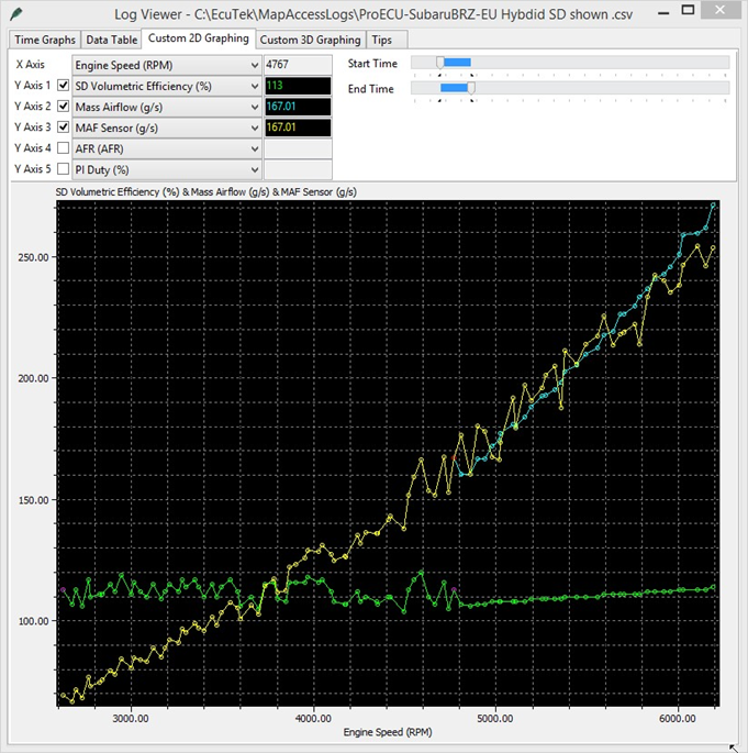
See how much smoother the Mass Airflow and Speed Density parameters are when they come from the RaceROM Speed Density map!
Logging SD Flags
RaceROM's SD code has a logging parameter for SD activation so that you can check witch thresholds have been exceeded and when SD is active. Logging parameter is called SD flags and the values are additive (15 = 1 + 2 + 4 + 8) the individual flag states are
0x1 - SD Active (when all thresholds are exceeded)
0x2 - MAF threshold exceeded
0x4 - MAP threshold exceeded
0x8 - RPM threshold exceeded
Table of Contents
Supplemental Content
Platform Specific
- BRZ/FRS/GT86 ProECU Tuning Guide
- BRZ/FRS/GT86 RaceROM Tuning Guide
- BRZ Common Tuning Questions
- Programming, Vehicle Tools & Logging Error Messages
- BRZ/FRS/GT86: 750cc Injector Installation and Calibration
- BRZ/FRS/GT86 FAQ
- BRZ/FRS/GT86 (2012-18); which tuning ROM?
- BRZ/FRS/GT86 DTC Codes
- BRZ/FRS/GT86 Technical Service Bulletins (TSB)
- Subaru BRZ Sequential/Dog Engagement Transmission Gear Shift Setup
- BRZ - Live Tuning
- BRZ CAM Activation
General
EcuTek ProECU tuning tools tools should only be used by experienced tuners who understand the product and engine calibration.
If you do not fully understand this product then you WILL damage your engine, ECU or your vehicle.
Please ensure you fully read all EcuTek manuals BEFORE attempting to use ProECU with your laptop or your vehicle.
Use with extreme caution and understanding at all times, if in doubt then do not proceed.
EcuTek accepts no responsibility for any damage to the engine, ECU or any part of the vehicle that results directly or indirectly from using the product.
** If you are in any doubt that you do NOT have the experience required to use this product then you should NOT USE IT **
Retail customers
** If you have any doubt that you do NOT have the experience required to use this product then you should NOT USE IT, you should simply contact your EcuTek Master Tuner shown clearly on the top of your Programming Kit or visit your preferred tuning shop to have a professional tuner use it for you **