BRZ/FRS/GT86 Re-Scaling the Factory Air Fuel Ratio Sensor

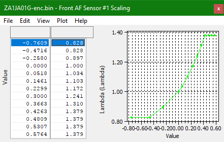
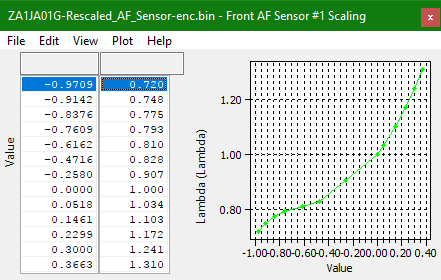
You can see we have re-scaled the input axis and also the output of the map for the front A/F Sensor #1 it is now re-scaled down to 0.72 Lambda (10.5:1).
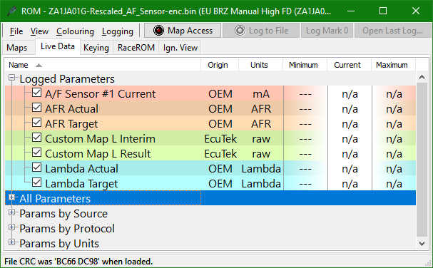
The process of re-scaling involves using a suitable wide-band O2 sensor and the factory sensor logging parameters, (for this example we have imported an Innovate LM-2 external sensor directly into the log covered later in document)
- A/F Sensor #1 Current (mA)
- Lambda Actual (from OEM sensor)
- LM-O2 (any wideband value would work the image below shows the wide-band import through custom map L)
To complete the re-scaling, adjust the Front A/F Sensor #1 scaling map Lambda values to match the wide band values and the A/F Sensor #1 Current values (first column) to the current corresponding to the wideband lambda value. See the image below
Re-calibration is best performed in steady state on a dyno so that the sensors have a chance to stabilise, good results can be achieved with some effort. The example ROMs also contain this sensor scaling to use as a base if required. Although the factory sensor readings cannot be trusted below 0.9 Lambda, a re-scaled A/F sensor can be considered a good reference, an external wide-band O2 sensor should always be used for tuning, this should be considered mandatory when tuning forced-induction vehicles.
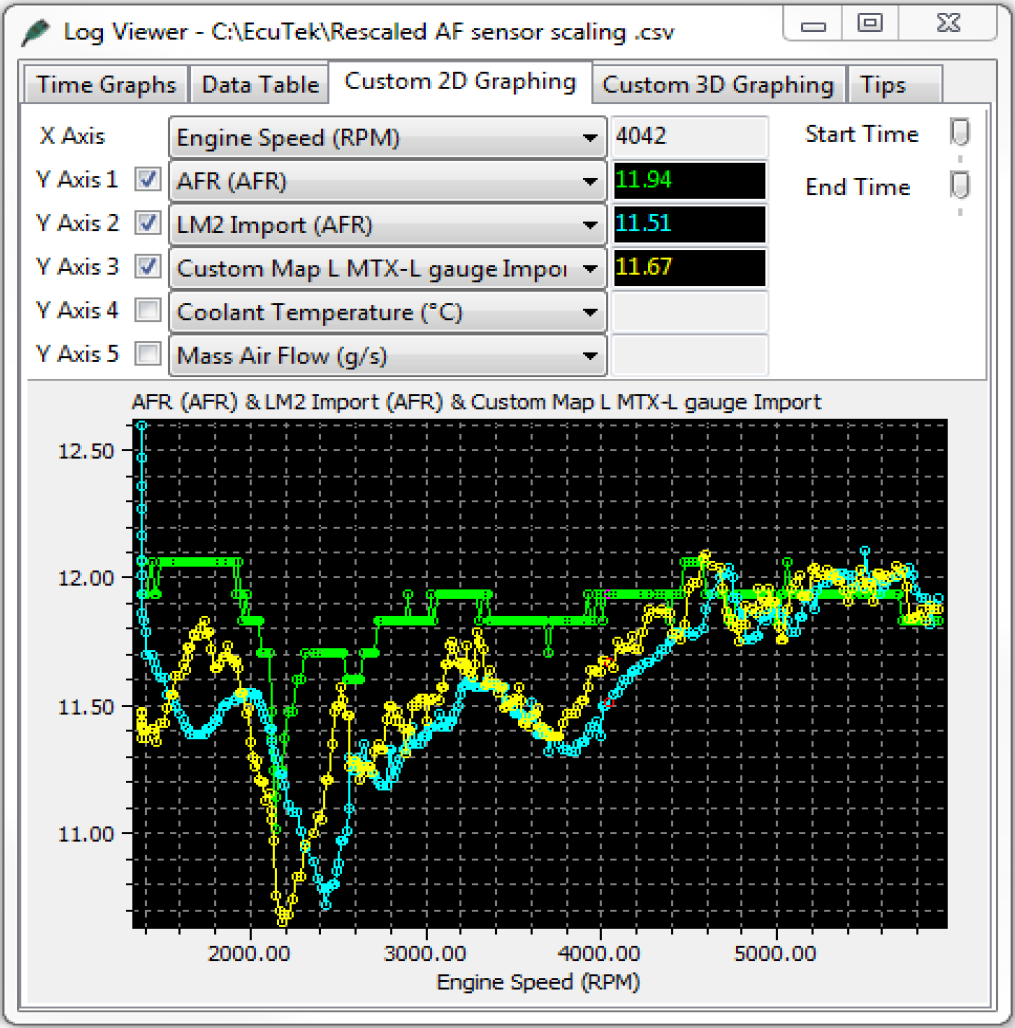
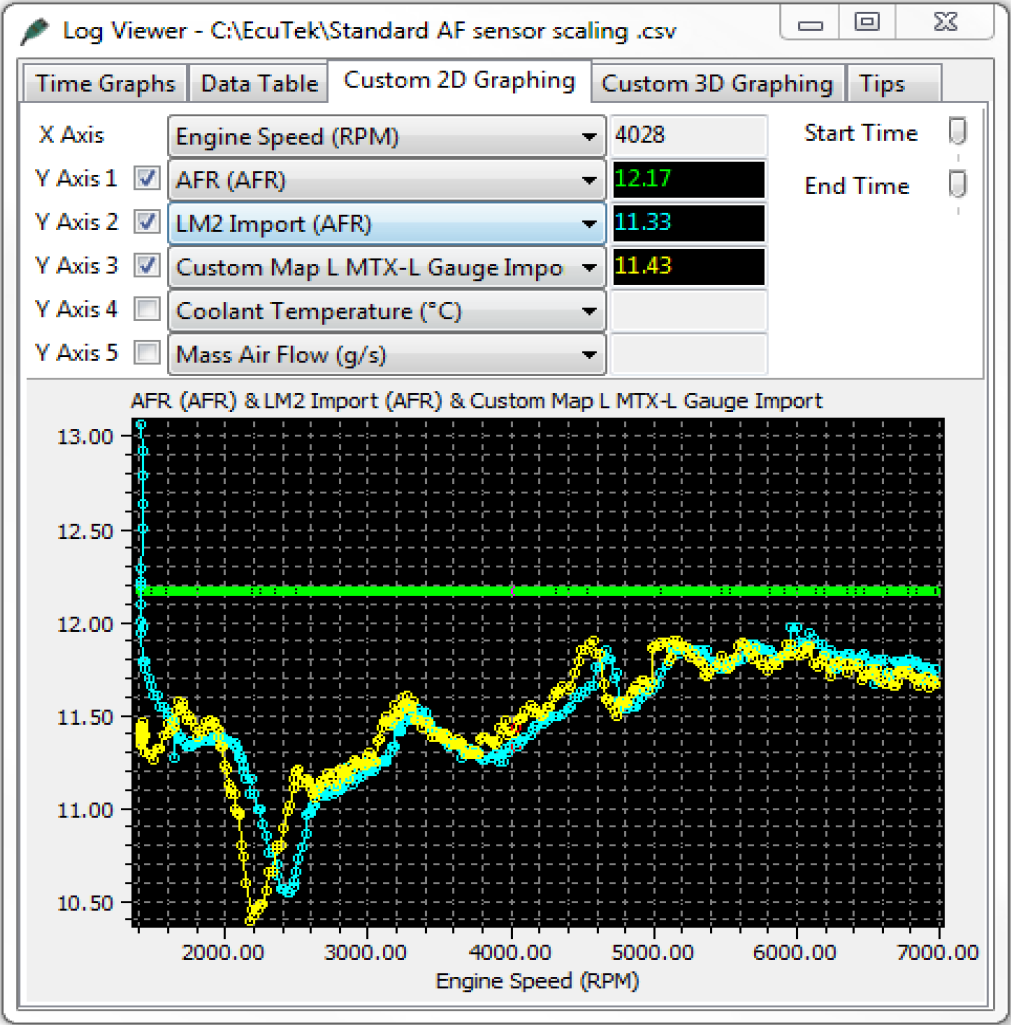
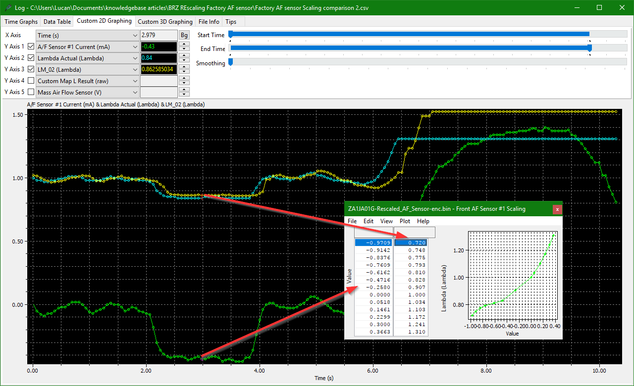
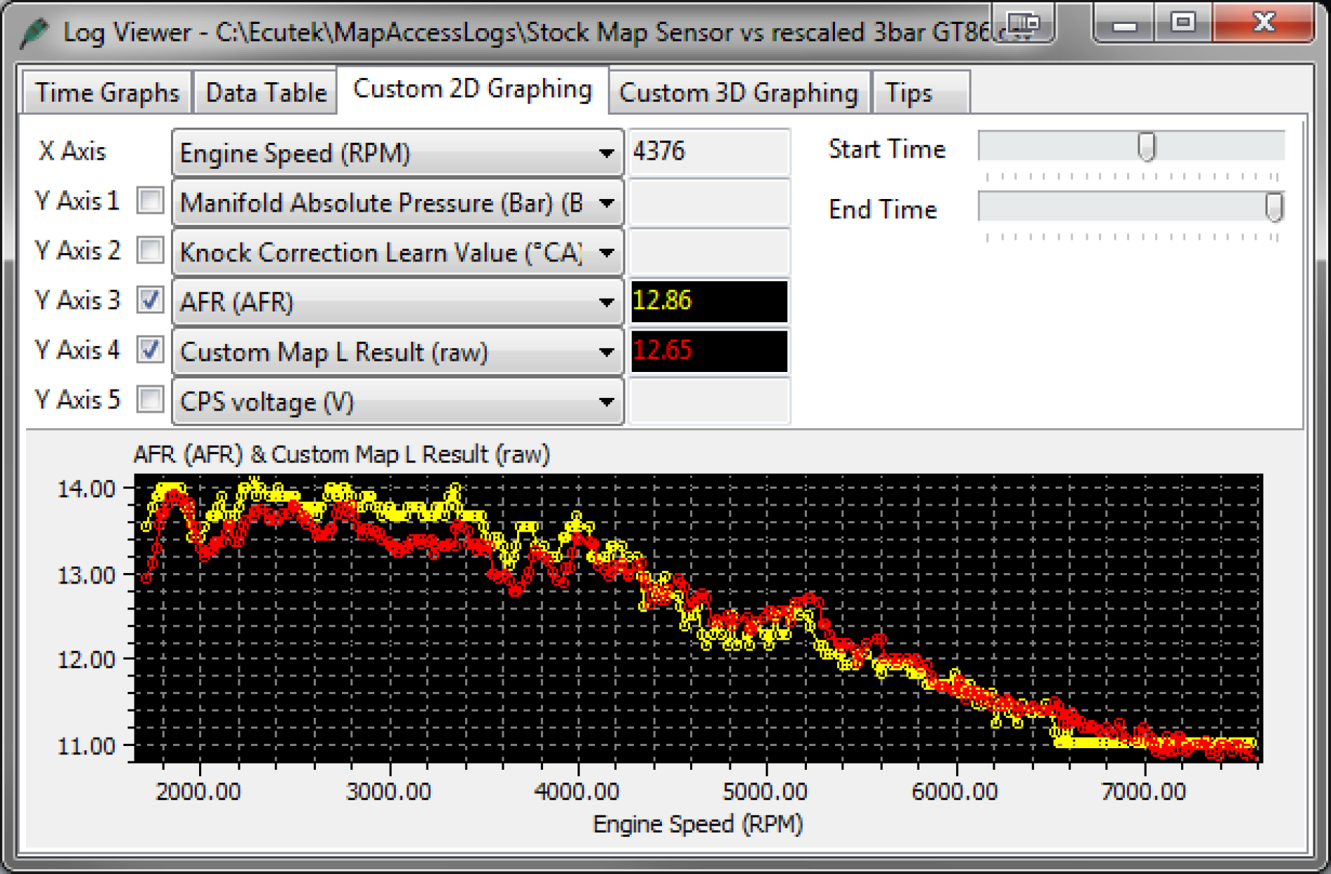
In the screenshot above the first log file shows the factory A/F sensor reading has flat-lined at 12.17:1 AFR (green log file line) but the right-hand-side log file shows the sensor re-scaled and the AFR reading more accurately at 11.94:1.
The factory wide-range sensor has even shown AFR as low as 11:1 AFR/0.75 Lambda, which is the current richest AFR reading it can show.
Installing and Importing the Wideband Sensor into the ECU
There are a couple of ways to import wideband sensors directly into ProECU it can even be done manually with log marks and excel if required. The option that is most simply used is to import a chassis dyno’s Innovate LM2 sensor reading into ProECU, this is a plug-and-play feature of ProECU and you simply get the LM2 working in Innovate Logworks software then close logworks and open ProECU, open your ROM and the LM2 logging will be shown in the Live Data capture window. For more information see the LM2 information on our Website.
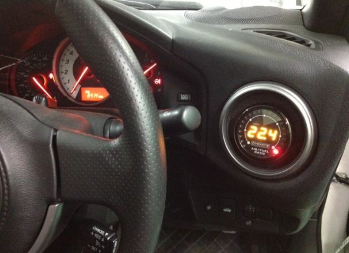
On our own EcuTek development vehicle we have fitted an Innovate MTX-L wide-band AFR gauge into the dashboard air duct and have welded an extra lambda sensor fitting into our exhaust manifold/header to accept the additional wide-band sensor.
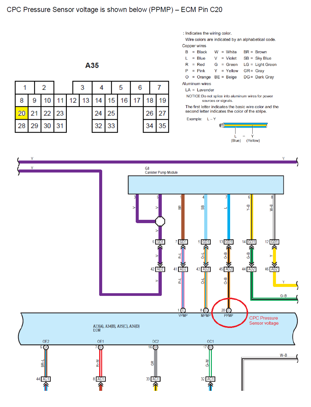
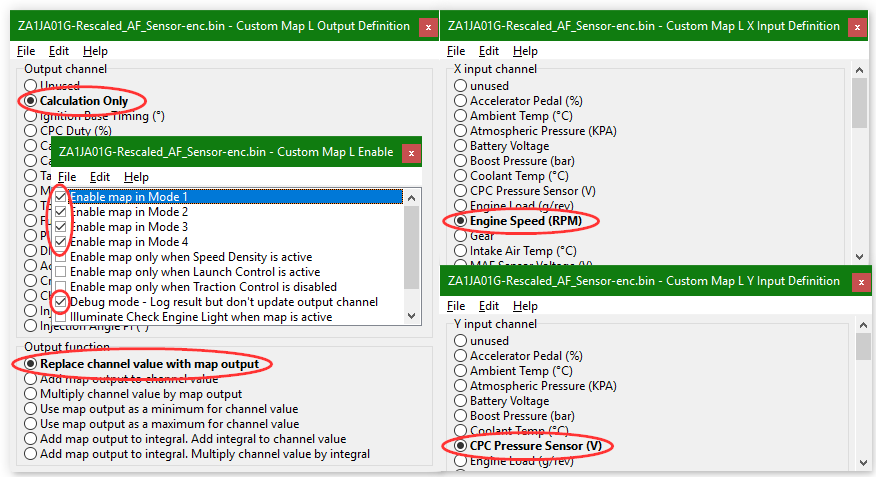
The Innovate MTX-L gauge has an analogue 0-5V output and we have imported this into the factory ECU via one of the Custom Maps Auxiliary ECU Input pins, the auxilary input pin chosen in this example was the "CPC Pressure Sensor Voltage" input but you could use any of the other available inputs for this task.
USDM variants (C,D,E and F) of this vehicle use the CPC Pressure Sensor to derive the Atmospheric Pressure Reading. Other variants use the MAP Sensor instead. If you re-purpose the CPC Pressure Sensor input on a USDM vehicle then the Atmospheric Pressure calculation will be incorrect. We have added a checkbox on affected vehicles to force the ECU to use the MAP sensor for the Atmospheric Pressure Calculation. Please enable this feature when re-purposing the CPC Pressure Sensor on a USDM vehicle.

The signal output from the wide-band can be wired directly to the pins of the ECU if required, below is a wiring diagram that may help you. Be sure to check the wiring diagram for your vehicle to see if it matches.
To import the sensor into custom maps so that the 0-5V signal can be used you can follow the example below. In this example we have configured Custom Map L to import a Innovate MTX-L Gauge 0-5v output and create a AFR value.
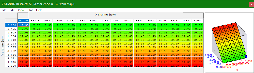
The Y axis shows the 0 – 5 volt input from the wideband gauge and Custom Map L converts the voltage to an AFR. The values in the map could also be Lambda if preferred.
You will see that Custom Map L is enabled in all modes but the DEBUG check box is unchecked, this means the output of the map will simply be an AFR value that can be used with other Custom Maps.
Other products such as the Innovate LC1 and AEM AFR gauges also have a 0-5V output and could also be used.
In our log-file screen shot shown previously we had two different wide-band sensors imported into ProECU: the Innovate LM2 and the Innovate MTX-L Gauge, as well as the rescaled factory AF sensor. Below you can see the red Custom Map L Result line showing the MTX-L gauge output that has been imported into the ECU, also the yellow line, which is the rescaled factory AF sensor. They are quite close but the factory sensor should not be relied upon for accuracy.
Using the imported value to take actions
It is possible to set up a custom map to protect the engine for an excessively rich or lean condition, and this can prove useful on a forced-induction vehicle. We will not cover how to set up these safe guard maps in this article, but please search the knowledge base for the specific set up you require. Some ideas for Safe Guards are discussed below.
You could create a Custom Map that would put on a CEL or close the throttle should the wide-band AFR reading go leaner than 13.5:1 AFR or richer than 10:1 AFR when on full load with the map only active over a certain engine load (full power).
To do this you could calibrate your fuelling as normal and once the map is profiled (Target AFR as such) copy the values into a Custom Map against RPM and Load (basically a copy of your fuel map if your MAF scaling is correct and your fuel map actually matches your true AFR).
You would then use the output of this Custom Map as the input to another Custom Map. Then have the True Wide-band Custom Map input compare to the Target AFR Input then make your decision as to the actions to take when the two values move apart. This feature might just save an expensive engine.
Examples might be
- Increase the Injection Volume for a Lean AFR
- illuminate the Check engine light (CEL) for a Lean or Rich condition
- Retard the ignition Timing aggressively to reduce power
- Reduce the desired Torque to close the throttle
- Dramatically reduce waste-gate duty for turbocharged vehicles.
If you have any questions, please do not hesitate to contact us with the information below.