Honda RaceROM Supplement
- Brandyn Mowat
![]()
ProECU Honda RaceROM Tuning Guide Supplement
Map Switching
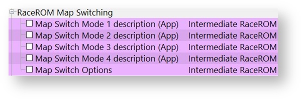
Four-way Map Switching (with rev-counter indication) Use Custom Maps to create four different calibrations; swap between them conveniently by using the cruise control switchgear or using ECU connect with a Bluetooth interface. There are options to name Each map switch mode which is limited to 64 characters, though text this long may not display correctly on the device. Simply enter the text into the desired MS modes to display it on the device when using ECU Connect.
Launch Control
Adding the Race ROM feature file allows you to enable Adjustable Launch Control which when set up can be used to make adjustment of the launch RPM live, this is done using the cruise control switchgear or ECU connect when using the Bluetooth interface.
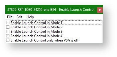
Launch control will become active when the it is enabled in the current Map switch mode, the vehicle speed is below the threshold and the Accelerator threshold has been is exceeded. There are launch control adjustment increments that can be changed for finer adjustment of the Launch RPM if required.
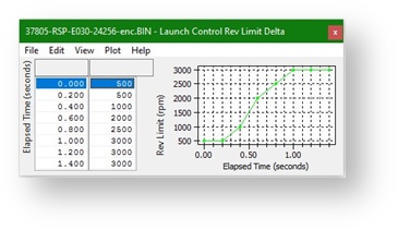
The Launch control Rev limit hysteresis value will control when the fuel cut is stopped and injection restarts. When the launch is in progress and the vehicle starts to move the Launch control Rev Limit Delta map is used to progressively raise the rev limit by the value in the map until the time limits have expired. If you need to perform traction control after the launch has completed.
Flat Foot Shift
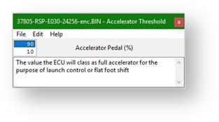
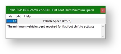
Flat-Foot Shift allow safe full-throttle gearshifts by reducing the engine torque and by controlling the air-fuel ratio during the shift. When enabled in a MS mode a Flat foot shift will start when the minimum vehicle speed is exceeded, the Clutch switch is triggered and the accel pedal is above the Accelerator threshold set for both LC and FFS (threshold value is in the LC map tree).
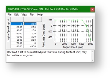
When the FFS mode is active it will set a temporary rev limit at the current RPM +the value in the Flat Foot Shift Rev Limit Delta map (which can be positive or negative) and use the hysteresis value to disable the cut.
When in the FFS mode the ECU will use the FFS Ignition Timing Adjustment and Target AFR values which can be adjusted if required. You can also adjust the deactivation delay for the FFS rev limit and set a re-arm timer to prevent accidental reactivation.
When using flat foot shift it can inadvertently be activated by drivers resting their foot on the clutch pedal. Without a clutch switch logging parameter, you will have to rely on examining the log for any strange full throttle timing/ AFR target changes when you suspect the FFS is activating when not required.
Downshift AutoBlip
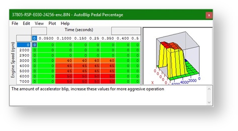
Downshift Auto-Blip Provides a smooth entry to the next lower gear. To trigger an AutoBlip (AB) you will need to be above the vehicle speed threshold and apply the brake then clutch switch, the throttle will be increased by the set percentage for the time given in the AutoBlip Pedal Percentage map. AutoBlip works by altering the Accel pedal input which in turn opens the throttle, if more throttle opening is required or the timing needs to be altered, simply change the values in this map.
E85 and Flex Fuel
With RaceROM Custom maps you can create a dedicated calibration for running E85 ethanol fuel or a Flex-Fuel variant, this is a similar set up to other EcuTek platforms.
When running E85 we are able extract more energy from the fuel and this leads to more power. Any 0-5V capable Flex fuel sensor can be used and it can be wired into any of the available 0-5 Inputs on the ECU, we would recommend using the Rear O2 sensor voltage input for Flex fuel importing which is covered in the next section.
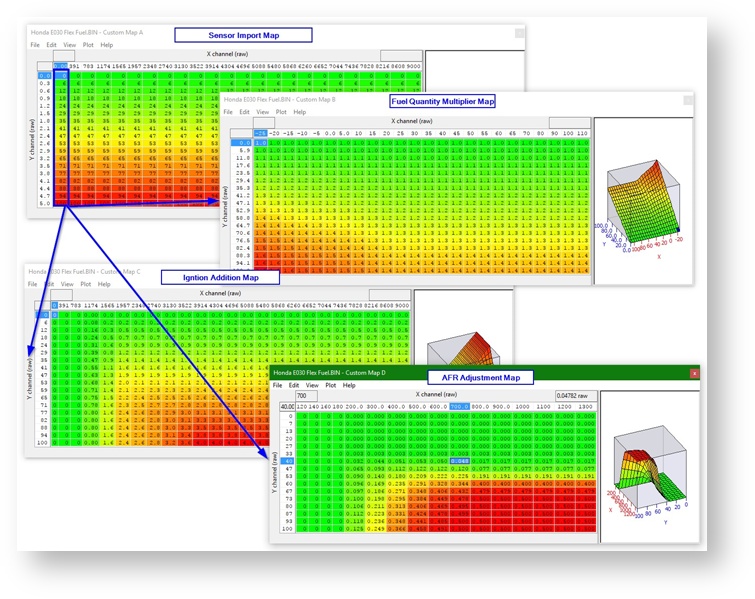
Several adjustments will need to be made in the calibration to adequately adjust the tune for E85 or flex fuel, these are outlined below. The maps are set up similar to below.
Fuel Volume
When running on E85 we need to increase the amount of fuel volume that is added per cylinder fill, the extra fuel volume amount is typically between 25% and 35% more depending on the method used to increase the volume.
Ignition Timing
Along with extra fuel volume we also need to advance the Ignition timing as Ethanol takes longer to burn and longer to release all its energy, for this reason we needed to advance the timing on full load.
Cranking Fuel
In addition, cranking fuel is normally a fixed injection volume amount and needs increasing independently of the main fuel volume calculations.
Using Custom Maps it possible to adjust the Ignition and Fuel for the current true Ethanol Content Ratio, this eliminates the risk of engine damage and also avoids having to run an empty tank before refuelling with Ethanol. In addition the tuning will always be correct for whatever the current Ethanol Ratio is.
Another point worth mentioning is the fact that you are injecting 30% more fuel that the stock injection system will be at 100% by 230-240bhp instead of 280-300bhp for regular gas (petrol)
NOTE: On Forced Induction models with higher cylinder pressure the same amount of Ignition Advance should not be used, take care as E85 doesn’t knock very easily. So to run on E85 we have to make the following calibration changes using Custom Maps.
- Adjust Ignition Timing on full load (depending on your region and modifications)
- Increase Injection Volume Amount by around +30% everywhere
You may find you also need to Increase Injector Open Time during Cranking by 30 to 50% depending on Coolant Temp however only if the normal fuel quantity multiplication does not give enough resolution.
Boost Control
Boost control can be set up using the OEM ECU and EcuTek’s RaceROM Custom maps. The feature can be set up to be a simple open loop WG duty map or a full closed loop system with adjustable target, compensations and failsafe’s, it’s all down to the number of maps available and the time spent when calibrating. Using the Carbon Purge Canister (CPC) valve will require some wiring to be made.
We believe the actual valve is down with the carbon canister at the back of the car (unconfirmed). You may just as easily be able to wire straight to the ECU though using the pinouts below.
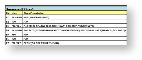
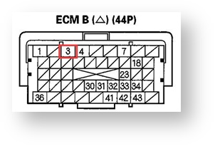
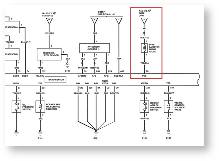
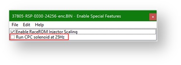
RaceROM custom maps also allows for 1x ECU Output Solenoid Driver (Frequency Based) by repurposing the factory CPC (Carbon Purge Canister) output driven at a duty cycle of your choice. This can be used as a wastegate solenoid control valve on turbocharged installations allowing features like closed loop boost control to be created.
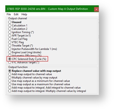
The CPC solenoid valve runs at roughly 12hz operating frequency normally but using RaceROM code allows you to set the Frequency to 25Hz which is far more suitable for most popular aftermarket Wastegate solenoid valves. To set the solenoid valve operating frequency simply select the check box in the RaceROM special features menu.
To set up custom maps to output a duty cycle the following functions will be required
- A boost target value
- Some corrections and adjustments e.g. custom parameters slider or AIT target corrections
- A base wastegate duty map
- A boost error calculation map (using boost target and MAP)
- A series of correction maps to make it closed loop (if you wish), this would include maps to support a proportional and an integral wastegate duty correction.
- Finally, failsafe’s to protect the engine if the boost pressure goes too high.
The end result of this will look like the following example Maps.
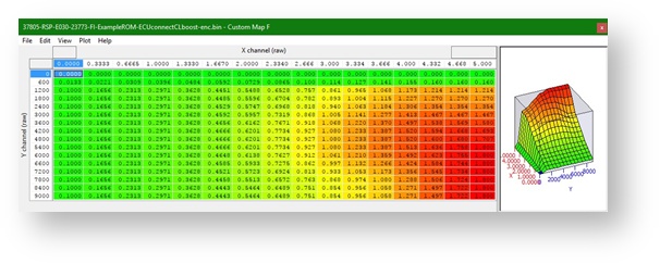
Custom Map F sets the Target Boost in BAR absolute into calculation channel 1, the x axis is accel pedal and the y axis is engine speed, this map is active all of the time.
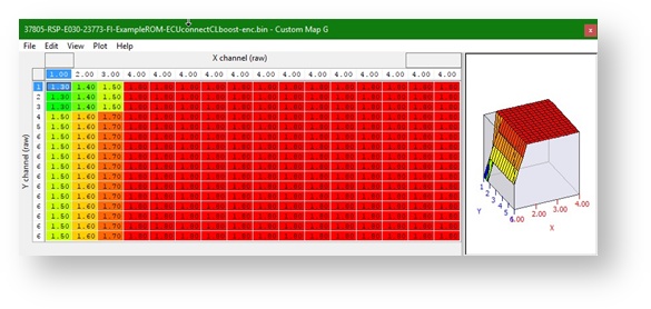
Custom Map G is Per Gear and Mode that limits the channel value by the output of this map. The x axis is map switch mode and the y axis gear, the map is active full time.
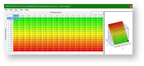
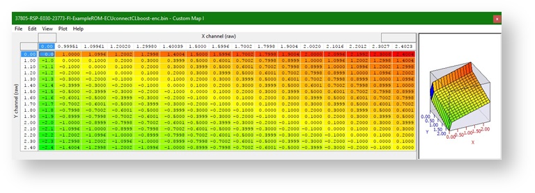
Custom Map H is App boost slider that limits the maximum channel value depending on the ECU Connect custom parameter 1. The x axis is accel pedal voltage and the Y axis is the custom input parameter.
Custom Map I is Boost Error calculated by comparing MAP to boost target defined at the end of all of the compensations and corrections (this case its map H), it compares the current MAP (x axis to the boost target from map H (y axis) and is active full time.
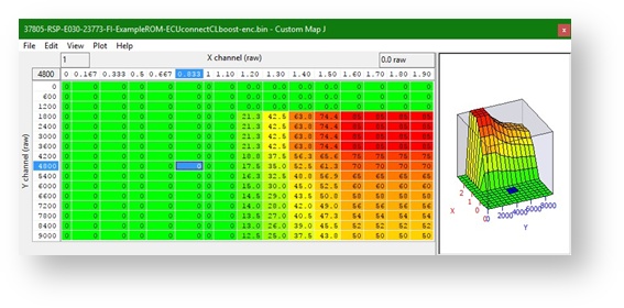
Custom Map J is Base WG Duty, this outputs directly to the CPC solenoid output and has boost target on the x axis and engine speed on the y axis. It is active full time.
Custom Map K is Proportional correction to WG duty cycle, it adds a correction value to the channel value (which is cpc duty cycle) based on the boost error calculated in map I. the Y axis is boost error (custom map I) and the x axis is the boost tagret (custom map H), this map is only active when it gets to a positive boost pressure.

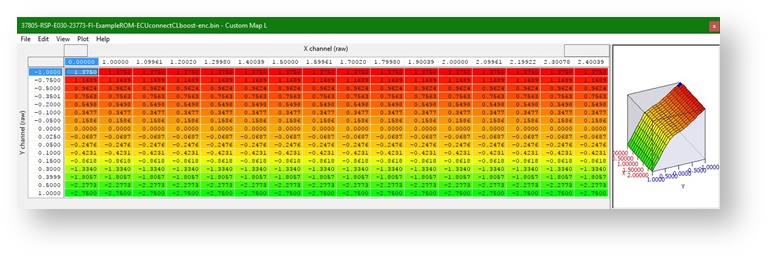
Custom Map L is Integral correction to WG duty, it calculates the integral value and adds it to the channel value (which is cpc duty cycle) based on the boost error calculated in map I. the Y axis is boost error (custom map I) and the x axis is the boost target (custom map H), this map is only active when it gets to a positive boost pressure and it has limits set to +5% and -50%.
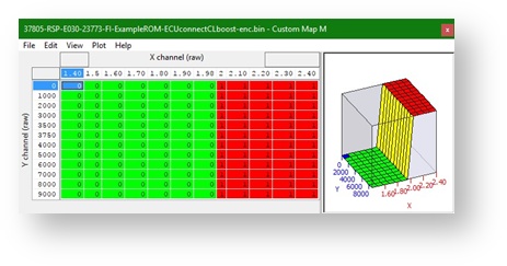
Custom Map M is Boost Cut, this map sets the minimum value output of the fuel cut flag channel (use the “use as minimum channel value” output as the replace function overwrites rev limiters stopping them from working correctly). It is only active when it hits the boost limit and has a 1 second deactivation delay.
There are many other compensations for AIT and wheel slip etc that could be added however for this example it has been kept as simple as possible.
Auxiliary Inputs & Outputs
Custom Maps Inputs
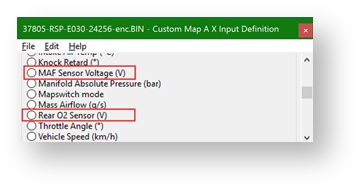
The RaceROM custom code allows you to hijack 2x ECU Voltage Inputs (0-5V), these can be used to import sensor signals into custom maps and extend the functionality of the ECU. These two inputs are found in the custom maps axis input maps as per other vehicles. The two inputs to custom maps are input through the MAF sensor voltage (with the MAF removed, DTCs disabled and running full time SD) as below and the Rear O2 sensor signal with the Rear Oxygen sensor removed and the DTCs disabled.
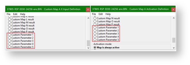
There are also Customisable Channels that interact with the EcuConnect App. These are set up in the ROM and interpreted by the app on a mobile device over Bluetooth. These values can be used as an axis and are customisable as per the feature set up. To import a custom Parameter into a custom map simply choose it as one of the axis values or activation definition parameters.
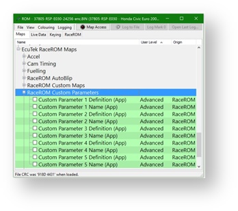
Setting up the parameters is covered in a later section but they are found in the RaceROM Custom Parameters tree in the ROM
Custom Map Outputs
RaceRom Custom maps can output to any available channel defined in the ECU, this means that you can make adjustments for AFR target, Fuel cut or camshaft advance. This allows you to compensate for many different engine and running conditions and can assist in tuning the vehicle.
Custom maps also allows for 1x ECU Output Solenoid Driver (Frequency Based) by repurposing the factory CPC (Carbon Purge Canister) output, this is covered in the previous section of the manual regarding boost control. The outputs can be modify the output channel value by
- Replacing the value totally (be wary of these as they can stop other functions from working)
- An addition or multiplication of the current value
- It can be used to cap the minimum or maximum of the channel (useful for limiting boost targets etc)
- An integral value can be calculated using the output which can then be added or multiplied by the channel value.
There are advantages and disadvantages to each method and they should be selected with caution and understanding. There are more details on what the outputs do and how to use them in the Custom maps manual.
Custom Parameters
Custom Parameters provides five new inputs into the ECU that can be adjusted using an iOS device, these can be used to adjust Custom Maps. Though at first this ground breaking feature may seem difficult to understand and you may not comprehend the ‘how and why’ you might use these features the reality is they provide the ability to control features and functions in the factory ECU that were never before possible, and all controlled using a iPhone (or iPad/Android Device).
The five inputs are configured using ProECU and can be setup as a Switch, Slider control, a Numerical value, a List Box, or a Momentary Button.
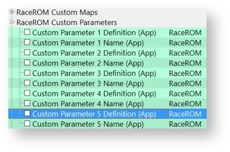
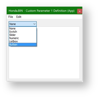
Each of the 5 Custom Parameters have a Definition option – to define how the Custom parameter will work and a Name box where the description for the map can be written and this will be displayed in ECU Connect under the specific custom feature.
Each Custom Parameter, once configured, could be used a Custom Map Input Axis value or even as a Custom Map Activation Definition, see below.

So for Activation, when using ECU Connect and a switch is ‘enabled’ or a ‘slider’ moved to a certain position and its ‘above or below’ a threshold then a certain Custom Map would become active.
Equally the Custom Parameter input into a Custom Map could adjust the Ignition, the fuelling, the Inlet or Exhaust cam timing (or both at the same time), it could add a fuel cut flag to act as a safe mode. Custom Parameters makes the following features possible,
- Adjustable Boost - set min/max boost with driver-adjustable slider control
- Adjustable Traction Control - use a slider control for live variation of TC gain
- Live Adjustments - use slider or numerical control to add/remove ignition timing, adjust fuelling, vary cam timing or alter custom map outputs
- Live Adjustment - of the power output, also engage the CPC solenoid
- Valet Mode - turn this ON or OFF using your handheld device
All these features and many more can be created in Custom Maps and adjusted and controlled using your iOS device, the limitation is simply your imagination. Here are some examples of what is possible:
- Turn the VTEC ON and OFF whenever you like
- Configure a pit lane Speed Limiter and even import a gear level switch to enable the map
- Add and remove Ignition Timing
- Adjust the weighting factor on a throttle and/or ignition based traction control
- Adjust the maximum allowed boost pressure using the slider
If you would like further examples of various custom input parameter set-ups either contact support@ecutek.com or view the EcuTek Knowledge Base
EcuTek ProECU tuning tools tools should only be used by experienced tuners who understand the product and engine calibration.
If you do not fully understand this product then you WILL damage your engine, ECU or your vehicle.
Please ensure you fully read all EcuTek manuals BEFORE attempting to use ProECU with your laptop or your vehicle.
Use with extreme caution and understanding at all times, if in doubt then do not proceed.
EcuTek accepts no responsibility for any damage to the engine, ECU or any part of the vehicle that results directly or indirectly from using the product.
** If you are in any doubt that you do NOT have the experience required to use this product then you should NOT USE IT **
Retail customers
** If you have any doubt that you do NOT have the experience required to use this product then you should NOT USE IT, you should simply contact your EcuTek Master Tuner shown clearly on the top of your Programming Kit or visit your preferred tuning shop to have a professional tuner use it for you **