BRZ/FRS/GT86 ProECU Tuning Guide
- Brandyn Mowat

BRZ/FRS/GT86 ProECU Tuning Guide
Accelerator
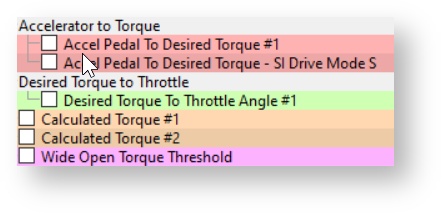
Accel Pedal to Desired Torque
This map defines the desired engine torque output for a set Engine Speed and Accelerator Pedal angle.
Wide Open Torque Threshold
This map is used to calculate the percentage of maximum torque. The value in this map is divided by the value output from Accel Pedal to Desired Torque and is used as the X axis input into the Desired Torque to Throttle Opening map. Raising these values could stop you from getting full throttle butterfly opening. Reducing these values would mean the throttle butterfly would be open further for the same accel pedal angle (Torque Demand amount).
For more information on accelerator pedal and torque control check out our article Subaru Torque Control
Map List
Live Data Parameters
- Accelerator Angle
- Accelerator Pedal Position #1 and #2
- Accelerator Pedal Position Sensor #1 and #2
- Throttle Angle
- Throttle Position
- Throttle Position Commanded
- Throttle Position Relative
- Throttle Position Sensor #1 - #2
Camshaft Timing
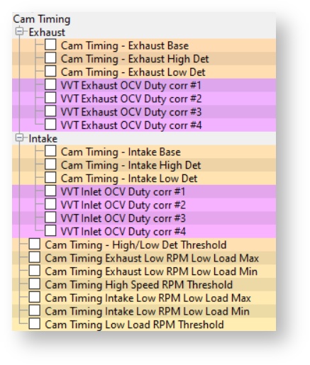
Cam Timing – Exhaust & Intake
There are 3 maps to control each of the intake and exhaust cams. The base map interpolates against either the Low Det or High Det maps to control the cam angle. Which map is chosen depends on the current advance multiplier value.
Cam Timing - High/Low Det Threshold
This is the threshold that dictates which cam timing map will be chosen, below 0.1 Advance
Multiplier (engine knocking) the High Det cam map will be used, above 0.4 Advance Multiplier the Low Det cam map will be used (engine not knocking). So 99% of the time the Low Det map will be used. We suggest that the values between the Base and Low Det maps are similar.
After starting the engine the Exhaust cam takes some time to become active, up to 30 seconds. If a power test is made whilst the Exhaust VVT is not active then a significant amount of power and torque will be lost.
There are also various issues with VVT control on the FA20 engine, see the Questions section for some of the issues and more specific information.
Map List
Live Data Parameters
- VVT Aim Angle #1 and #2
- VVT Exhaust Angle #1 and #2
- VVT Exhaust Angle Target #1 and #2
- VVT Exhaust OCV Duty #1 and #2
- VVT Intake Angle #1 and #2
- VVT Intake Angle Target #1 and #2
- VVT Intake OCV Duty #1 and #2
Fuelling
Fuel Map
Mode 1 to Mode 4 refers to the different map slots or "modes" offered by RaceROM Map switching, rather than to the different injection mode styles utilised by this platform
The Fuel Maps contain target AFR based on Engine Speed (RPM) and Engine Load (grams/rev). These maps are used in both open loop and closed loop conditions. Fuel Map (Mode 1) will be used unless the ECU is Map Switched into another mode (Modes 2, 3 or 4). The X and Y axis scaling can be adjusted to suit higher RPMs or higher Engine Loads if required.
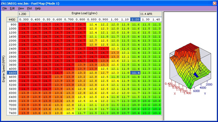
If the ECU is currently in Closed Loop mode (light load and below 4500rpm), then the Short Term Fuel Trims will be active. The target AFR in Closed Loop will be 14.7:1 AFR (Lambda 1), altering the fuel map values during closed loop control will not change the AFR (only the Fuel Trims will change to compensate for the deviation and will attempt to maintain Lambda 1 or 14.7 AFR).
If the ECU is in Open Loop mode (high load and high RPM), then the Short Term Fuel Trims will be inactive and set to zero. The AFR values shown in the Fuel Map in Open Loop are based on a stock intake and a known airflow amount, so the correct amount of fuel volume can be injected to deliver the indicated AFR.
If the Intake or Injectors have been replaced, then the MAF scaling or Injector scaling should be adjusted until the AFR value in the map is roughly achieved. Ensure that your actual engine load parameter shown in the data logging does not exceed the Engine Load Values shown in the X axis of the fuel map.
"Mode" refers to the map slot you are on. "Mode 1" being the base one used if not utilizing the map switching feature
Open and Closed Loop Control
Closed Loop is when the ECU is using the feedback control of the lambda sensors to maintain a steady 14.7:1 AFR (or Lambda 1). This closed loop target value cannot be altered from 14.7:1. The front ‘widerange’ AF sensor #1 is located before the Catalysers and allows the ECU to ‘adjust or trim’ the Fuel Injection volume amount very accurately so as to achieve the target AFR. This Fuel Trim can be seen under LIVE DATA as Fuel Trim Short Term and Fuel Trim Long Term. Closed Loop condition will be seen below 4000rpm and at light load conditions.
Open Loop is when the ECU is no longer using the feedback control of the lambda sensors to maintain a specific AFR but it will simply take an AFR value from the fuel map. This open loop AFR value will normally be lower (or richer) than 14.7:1 and as low as 10.5:1 depending on the exact model. The front ‘widerange’ AF sensor #1 can read to 12.2:1 AFR but has to be rescaled to read past 12.2AFR or 0.82Lambda, the accuracy is limited at richer AFR and it should not be completely trusted.
Open Loop Throttle Threshold Manual
Throttle angle for manual transmission above which fuelling goes open loop after the delay period expires.
Open Loop Per Gear RPM Thresholds Auto/Manual
Per gear RPM thresholds for AT/MT above which fuelling goes open loop. There is a pair of RPMs for each gear.
Open Loop Stationary RPM Threshold
When the vehicle is stationary the fuelling will go open loop above this RPM.
Open Loop Throttle Threshold High/Low Altitude Auto
Throttle angle for automatic transmission at high/low altitude above which fuelling goes open loop.
Fuel Trim Long Term Minimum and Maximum
These are the minimum and maximum allowed fuel trim to be applied in open loop. Set these to zero to avoid the closed loop fuel trims being applied in open loop.
Closed Loop AFR Adjustment #1 / #2
These 3D maps are used to fine tune the Injection amount during closed loop, they can also bias the AFR during transient conditions.
Closed Loop Max Vehicle Speed
This is the maximum allowed vehicle speed for the ECU to be in closed loop condition. Over this speed the ECU will switch to open loop but it may require other open loop conditions to be met before the transition to open loop.
Closed Loop Minimum Coolant Temperature
This is the minimum coolant temperature for the ECU to be in closed loop mode, below this value the ECU will be in open loop mode, used for emission control by manufacturers.
Closed Loop Delay Maximum Engine Load
The maximum allowed Engine Load for the Closed Loop Delay timer to work, the CL delay timer will prevent Open Loop until the timer has expired.
Closed to Open Loop Delay Periods
Delay periods when changing from closed to open loop fuelling. Reduce them to zero.
Delayed Open Loop Fuel Load Threshold
Injector load threshold, varying with RPM, above which fuelling will go open loop after a delay.
Delayed Open Loop Fuel Throttle Threshold
Throttle threshold, varying with RPM, above which fuelling will go open loop after a delay.
Throttle Delta Fuel Comp. (Delta) / (Delta) 2 / Coolant Temp.3
Base fuel enrichment factor applied during throttle movement, this can be increased and decreased to change the fuelling during transient conditions and sudden throttle movements.
AF Correction #3 Limit – Rear O2
These values should be set to zero if the rear O2 sensor is removed or repurposed along with the following map called AF Correction #3 CL Target Compensation Limits.
AF Correction #3 CL Target Compensation Limits
These Closed Loop Target Compensations values should be set to zero if the rear O2 is removed or repurposed along with the above map called AF Correction #3 Limit – Rear O2
Injection Control
Please note the following abbreviations will be used: DI = Direct Injection and PI = Port Injection
The Toyota developed Dual Injection system will operate in several different modes depending on the current engine conditions. The current Injection mode can be seen in the Live Data parameter called Injection Mode (D4-S).
The ECU will check the fuel map for a target AFR and then by using the current Mass Airflow amount (g/rev), it will deliver a required volume of fuel (ml) to achieve that AFR. The ECU will split the fuel delivery volume amount between the PI and DI injectors depending on the current Injection Mode.
| Injection Mode | When | Port Injection (PI) | Direct Injection (DI) |
|---|---|---|---|
| Mode 1 | After starting the engine | ON | OFF |
| Mode 2 | Between 3000rpm and 5000rpm (before closed loop) | OFF | ON |
| Mode 3 | Seen below 3000rpm | ON | ON |
| Mode 4 | Both sets off | OFF | OFF |
Fuel Injection Ratio Port to Direct - Cold - Warm - Hot
The current Injection Mode (PI/DI Ratio) is determined by the maps named Fuel Injection Ratio Port to Direct. There are 3 maps for engine cold, warm and hot conditions. These maps control the fuel delivery ratio between the PI and DI injectors. The values in the maps dictate the % ratio that a given volume of fuel will distribute between the PI and DI. As shown in the screen shot below of the factory map settings at 2000rpm and 0.8 Engine Load that the total Injection Volume amount (ml) will be split equally between the PI and DI (showing 50% in the map cell above). The PI delivery ratio amount will then reduce between 2800rpm and 3200rpm where at 3200rpm the PI will have stopped completely injecting at all.
Gasoline Direct injection Systems can only inject during the induction and compression phases of the engines cycle unlike the PI system which could also inject during the power and exhaust strokes, please keep in mind that the opening times for DI will be approximately half of what you would normally see when tuning a conventional port injection
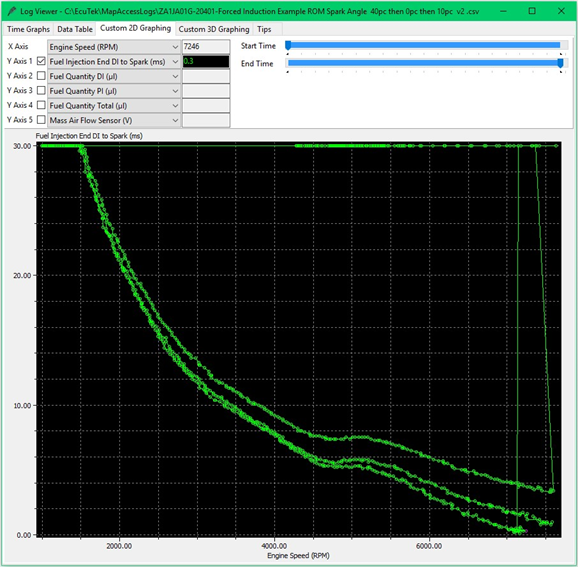
The logging parameter called Fuel Injection End DI to Spark (MS) is critical for DI tuning. It shows the time period left between the direct injector closing, and the time of the spark plug firing. It is critical to maximise the DI open time.
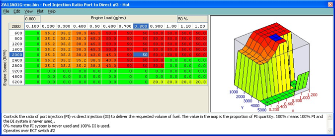
At 4800rpm, the PI will start to be phased back in and by 5200rpm the PI will deliver 20% of the required fuel volume. The PI ratio can be increased at higher RPM to provide more fuel delivery if required, especially on forced induction engines where the DI cannot supply the required amount of fuel that is needed. This system has been extensively developed and tested by Toyota and you should consider this fact when making changes.
Fuel Injection Ratio ECT Switch Threshold #1
The engine coolant temperature at which the ECU will switch from "Fuel Injection Ratio Port to Direct #1" - "Cold to Fuel Injection Ratio Port to Direct #2 - Warm". The top value is the switch temperature to map #2, and the lower value is coolant temp that it would switch back to #1.
Fuel Injection Ratio ECT Switch Threshold #2
The engine coolant temperature at which the ECU will switch from "Fuel Injection Ratio Port to Direct #2 - Warm" - "Cold to Fuel Injection Ratio Port to Direct #3 - Hot". The top value is the switch temperature to map #3, and the lower value is coolant temp that it would switch back to #2.
All 3 maps called "Fuel Injection Ratio Port to Direct” are set the same from the factory.
PI Ratio Threshold – Lower Limit / Upper Limit
If the fuel injection ratio Port to Direct #1, #2 & #3 maps are requesting values below the PI Ratio Threshold – Lower Limit (standard 35%) the ECU will automatically output 0% PI
If the fuel injection ratio Port to Direct #1, #2 & #3 maps are set above PI ratio Threshold – Upper Limit (standard 75%) the ECU will output 100% PI
PI Ratio Threshold – Load / RPM
These values will allow the ECU to ignore the PI Ratio Threshold - Lower / Upper limits if either PI Ratio Threshold - RPM or PI Ratio Threshold – Load are exceeded.
Live Data Parameters
- Direct Injection Timing
- Fuel Rail Pressure
- Injection Mode
- Injection Time Direct Final
- Injection Time Port Final
- Injection Volume
Port Injector Maps
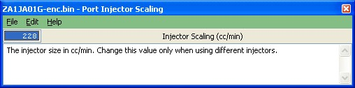
Port Injector Scaling
The PI injector size in cc/min. Change this value when larger Port Injectors have been fitted so the ECU can accurately calculate the PI open time required to deliver a requested volume of fuel. Also ensure that you change the Injector Opening Time Compensation map as per the injector manufacturer specifications.
Injector Opening Time Compensation
Often called ‘Injector Lag Time’/ ‘Injector Latency’ or ‘Injector Dead Time’, this is the time period (ms) that is required for the injector to energise and fully open. If larger injectors have been fitted they often need a longer time period to open.
The Y-axis may be Manifold Relative Pressure (mmHg) on return-less fuel rail systems, but it is not calibrated at present. Ensure that you change the Port Injector Scaling to match the larger injectors that have been fitted.
PI Firing Angle
The angle at which the port injector will open. The angle is measured before top dead centre (spark plug firing).
PI Minimum Fuel Volume
The minimum time fuel volume that the Port Injectors are allowed to open for, this may need reducing if larger Port Injectors are fitted.
Port Injector Manifold Relative Pressure Comp
This map is used to adjust the opening time of the port injectors for a given manifold pressure. The factory settings do not account for any positive pressure, but when working on a forced induction engine this map must be profiled to provide PI open time compensation for positive pressure and therefore ensuring the correct volume of fuel is delivered.
How to Maximise your PI and DI fueling
The PI can inject for a full two revolutions, Induction, Compression, Power and Exhaust, this is 720 degs and the logging parameter called PI Duty will show this as 0 – 100% so you can see when you have maxed out your Port Injectors.
With DI it becomes slightly more difficult as we can only inject during Induction and Compression but there are other factors that limit the maximum possible open time period, these are valve overlap and spark advance.
We have added certain maps to allow you to maximise the total fuel quantity that can be delivered from your PI and DI setup and the split ratio that can be achieved. We have DI firing angle maps and these can be used to maximise the fuel delivery from the DI system. Watching the fuel volume delivery parameters and the Fuel Injection End DI to Spark (ms) time you can fine tune the injection control.
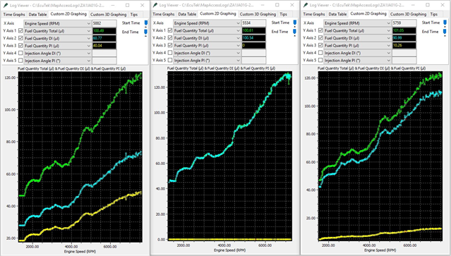
Fuel Quantity DI - the total fuel volume delivered by the Direct Injectors
Fuel Quantity PI - the total fuel volume delivered by the Port Injectors Fuel Quantity Total - the total fuel volume delivered in micro litres
Fuel Quantity Total will verify the PI and DI fueling calculation is correct and accurate. Here you can see the PI and DI split ratio is clearly shown in each example.
Left Log - 40% PI Ratio
Middle Log - 0% PI Ratio
Right Log - 10% PI Ratio
Fuel Injection End to PI Spark (ms)
This is the time period left between the port injector closing and the spark plug firing, not so important so the port injector can fire through a full 720 deg
Fuel Injection End DI to Spark (ms)
This is the time period left between the direct injector closing and the spark plug firing, critical to maximize the DI Open Time. This new DI to Spark logging parameter is important to maximise your PI and DI fuel delivery, see below where 3 power runs shown on the previous page were made with different PI/DI split ratios.
40% PI Ratio left 4ms between End of DI Injection and the Spark Plug firing
10% PI Ratio left less than 1ms between End of DI Injection and the Spark Plug firing
0% PI Ratio left less than 0.3ms between End of DI Injection and the Spark Plug firing and the engine was misfiring and was unable to finish the power run.
We would advise you do not you run below 1.0ms to allow a reasonable time for the fuel to mix before the spark plug fires.
How To Calibrate Larger Injectors
It’s very important that the ECU knows the true size of the Port Injectors that are fitted so it can accurately calculate the correct time period to open the injector to deliver a required volume of fuel.
After fitting larger port injectors the following maps will need rescaling.
- Port Injector Scaling
- Injector Opening Time Compensation
- Injector Minimum Open Time
Generally the replacement larger Port Injectors will be supplied with an Injector calibration size and that should be entered here.
The different Injectors will have different characteristics to the stock injectors and will normally take longer to open. This time period is referred to as ‘dead time, lag time or latency’ and this time period is affected by the current battery voltage. Using the manufacturers technical data, enter the correct lag times for a given voltage in the maps called ‘Injector Opening Time Compensation’.
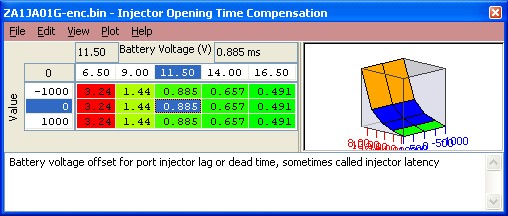
If this data is not available then we suggest you just change the Injector size then leave the battery voltage comp map until you see how the engine is currently running.
You should now follow the steps found in the BRZ/FRS/86/DIT WRX: How to Re-scale your MAF for Intake/Induction Changes section and pay attention to the fuel trims in closed loop and watch the wideband AFR sensor in Open loop to see how far out the AFR is compared to the fuel map targets.
As per the previous section the fuel map should be filled with a fixed value (like 12:1 AFR) for simplicity of adjusting the calibration and cross referencing with the wideband.
The Injector Opening Time Compensation values will have much more of an effect at Idle and light load when the Injector open times are much smaller (2-5ms at Idle and light load VS 1018ms for full load).
In addition, where larger Port Injectors are fitted it may be advantageous to fine tune the DI/PI ratio to ensure that the DI Injectors are delivering enough fuel volume and that the bigger PI injectors do not simply deliver all the fuel. They should supplement the DI and not replace it.
Remember that the Port Injectors can open up to 18ms at 6000rpm whereas the DI can only inject for less than half of that (due to Spark BTDC and valve overlap), so around 5ms MAX is recommended for DI.
Changes should also be made to the PI/DI ratio map along with the Min and Max allowed ratios for larger injectors, see the BRZ/FRS/GT86 RaceROM Tuning Guide Supplement: Boost Control & Forced Induction for further info.
Idle
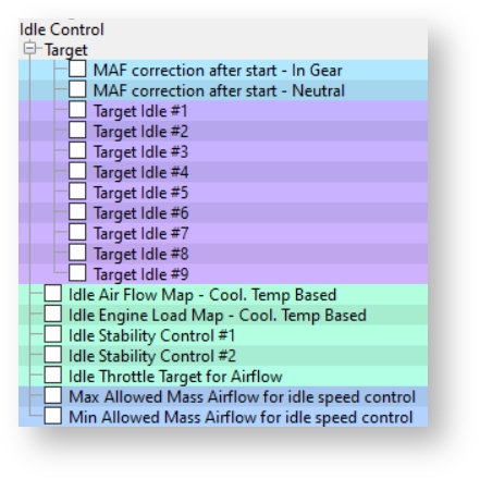
Controlling the Idle speed of an engine is a difficult task and the factory ECU has many targets and compensations to achieve this. The Idle Target maps set the target Idle speed for many different modes like drive, neutral, after starting, engine hot, load on (alternator or headlights etc). It is advised that you adjust all Idle maps by the same amount or simply set them all the same to avoid discrepancies in the idle engine speed.
Target Idle 1 to 9
Desired engine idle speed for a given coolant temperature.
Idle Air Flow Map – Cool. Temp Based
The mass airflow values in this map should be close to what the engine is running at Idle, this will help improve Idle stability.
Idle Engine Load Map – Cool. Temp Based
The engine load values in this map should be close to what the engine is running at Idle, this will help improve Idle stability.
Idle Stability Control #1 & #2
- X axis is RPM idle error
- Y axis is rate of change of engine speed
This map is used for Idle Speed error compensation, making the values bigger will make the Idle Speed error more aggressive for correction.
Map List
Live Data Parameters
- Engine Speed (RPM)
Ignition
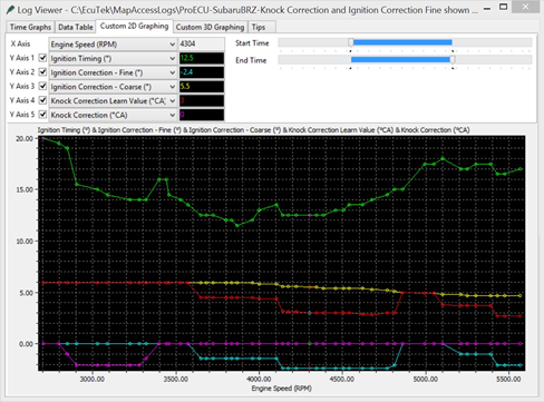
You can see below that the Ignition has learned some previous knock events (the Cyan line called Ignition Correction – Fine). This previous learned knock retard event is added during the Ignition calculation, you can see the Yellow line called Ignition Correction – Coarse has been reduced to the Knock Correction Learned Value (Red line).
The Yellow line is where the timing ‘could be’ and the Red line shows what’s actually been added after the Ignition Correction Fine has been applied.
You can also see the Knock Correction (Purple line) was also active around 3000rpm.
Ignition Base Map (Mode 1 to Mode 4)
Mode 1 to Mode 4 refers to the different map slots or "modes" offered by RaceROM Map switching, rather than to the different injection mode styles utilised by this platform
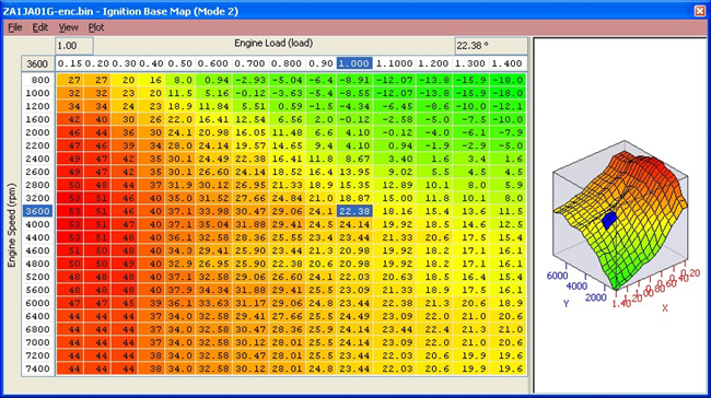
The ECU selects an Ignition Base Map depending on the current VVT status.
- VVT ON (Cam Timing working)
- VVT OFF (Cam Timing not working)
Under normal running the Ignition Base Map VVT On (Mode 1) will be used. If the ECU is Map Switched into another RaceROM mode (for example Mode 3) then Ignition Base Map (Mode 3) will be used without consideration for the VVT status. The X and Y axis scaling can be adjusted to suit higher RPM or higher Engine Loads if required.
Ignition Advance (Mode 1 to Mode 4)
Mode 1 to Mode 4 refers to the different map slots or "modes" offered by RaceROM Map switching, rather than to the different injection mode styles utilised by this platform
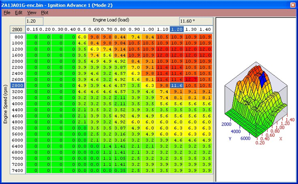
The Ignition Advance map is added to the Ignition Base map relative to the LIVE DATA parameter called Advance Multiplier (AM). The Ignition Advance map is also used as a coarse Ignition adjustment to advance and retard the Ignition timing for changing conditions like fuel quality, ambient temperature and altitude.
Advance Multiplier - Coarse Correction
The Advance Multiplier (AM) is dynamic and will change relative to the current amount of engine knocking (detonation). If the engine is knocking frequently and consistently then the AM will be low, if there is no knocking then the AM will be high. The AM moves between 0 and 1.
If the AM is 0 then NONE of the Ignition Advance map will be added to the Ignition Base map.
If the AM is 1 then ALL of the Ignition Advance map will be added to the Ignition Base map. If the AM is 0.73 then 73% of the current Ignition Advance map value will be added to the Ignition Base map.
The factory Ignition Advance map is calibrated to advance and retard the ignition timing by a greater degree in certain areas of the map (as seen in the screen shot above).
This is to ensure when the engine is knocking (and the AM decreases) that more Ignition timing is removed from areas where the engine is more susceptible to detonation (like peak torque). Areas where the engine is least likely to detonate the values are smaller (like light load).
The output of the Ignition Advance map is important and can be seen and logged in LIVE DATA as Knock Correction Learn Value.
So ‘for explanation purpose only’, if the Ignition Advance map was filled with 12 deg then the Knock Correction Learn Value would read 12 deg in LIVE DATA (assuming the AM is 1).
If the AM was 0.75 then the Knock Correction Learn Value would read 9 deg (12 * 0.75 = 9 deg).
Knock Correction
If the engine knocks then the ECU will immediately remove an amount of ignition timing (Knock Retard amount) and this will be shown in LIVE DATA as the Knock Correction parameter. After a Knock Correction event has occurred and an amount of Ignition timing has been removed from the current Ignition Timing calculation then the ECU will store 50% of that knock correction event to pre-empt a similar knock event at the same RPM and same Load the next time round. This is the long term ‘Ignition Fine Learning’ strategy.
Ignition Fine Learning
If the LIVE DATA parameter called Knock Correction shows a -4 deg has been removed from the current Ignition timing calculation then 50% of this Knock Correction amount (-2 deg) will be stored in memory for a given RPM and Engine Load range.
If a negative value is already stored for that RPM and Load then the value is simply added to stored ‘Fine Learning value’
If -1 deg was already stored in memory for a given RPM and Load then a further -2deg would also be added making a total of -3 deg stored for the same RPM/Load memory location.
The next time the engine passes the same RPM and Engine Load then the Fine Learning value (3 deg) would be recalled and subtracted from the Ignition Timing calculation at that point.
When the learned value is 50% or greater than the corresponding values in the Ignition Advance map then the AM will be decreased and all Fine Learning stored values are cleared and the process starts all over again.
In the event that no further knocking is experienced then the ECU will add positive Fine Learning values in +0.35 deg increments to build out the learned negative values.
When all negative values have been built out and the positive values are 50% or greater than the values in the Ignition Advance map then the AM will increase and therefore advance the whole ignition curve.
Ignition Compensations
There are many Ignition timing compensations that are added and subtracted to the Ignition calculation. Some are simple like Air Intake Temp (AIT) and after starting the engine, but others are more complex like transient conditions and overrun or during gear change etc.
Ignition Timing calculation
The final Ignition Timing calculation is computed like this:

It’s a very active and dynamic control strategy that will constantly adjust the ignition timing but it should not be fully trusted to ‘control the ignition’ especially on forced induction setups.
The final Ignition Timing logging parameter will include any compensations or corrections that have been made by the above maps.
Advance Multiplier - The highest advance multiplier number obtainable is 1, this will be achieved when there is no engine knocking present. If the engine constantly knocks or reduces the AM then the Advance map or the Base map should be reduced in that region (excluding other factors like fuel, temps and cam timing etc).
Advance Multiplier – Initial
This is the base default setting for the advance multiplier after ECU Programming or ECU Reset. This can be increased to 1 for tuning purpose so that 100% of the Ignition Advance map is added to the Ignition Base map. It is advised to reset back to its default value on the final flash of the ECU.
Advance Multiplier – Increment amount
The amount that the Advance Multiplier will increase during its learning period like after programming the ECU or carrying out a CLEAR DTCs command (which will also reset the ECU learning).
Coarse Ign Learning Load Range
The engine load range in which the ECU is allowed to change the advance multiplier.
Coarse Ign Learning RPM Range
The RPM range in which the ECU is allowed to change the advance multiplier.
Ignition Compensation Coarse Cylinder #1 - #4
This is a per cylinder Ignition compensation that is added to the current Ignition timing when certain conditions are met, see the following maps. The Ignition Timing logging parameter will include any per cylinder ignition retard that has been applied.
Ignition Correction Coarse ECT Minimum
Minimum coolant temperature that must be exceeded before coarse ignition correction will be active.
Ignition Correction Coarse Engine Load Minimum
The minimum Engine Load to be exceeded before Ignition Coarse Correction will be active.
Ignition Correction Coarse RPM Maximum
The maximum RPM that Ignition Coarse Correction will be active.
Ignition Timing – Air Intake Temp Compensation
Ignition timing compensation for Intake Air Temp, this map will only work if the 3d map called 'Ignition Timing - Air Intake Temp Threshold' is enabled.
Ignition Timing – Air Intake Temp Threshold
Ignition timing compensation for Intake Air Temp, this map defines when the 2d map called 'Ignition Timing - Air Intake Temp Compensation' is allowed to work.
Ignition Timing Minimum Allowed during FFS
The minimum allowed ignition during gear change or a RaceROM Flat Foot Shifting.
Ignition Retard when the Clutch is down
The amount of retard that is subtracted from the current ignition timing when the clutch is depressed.
Ignition Timing After Starting
This is used immediately after starting to heat the Catalyst quickly, this map might not be used in all regions due to different emission requirements.
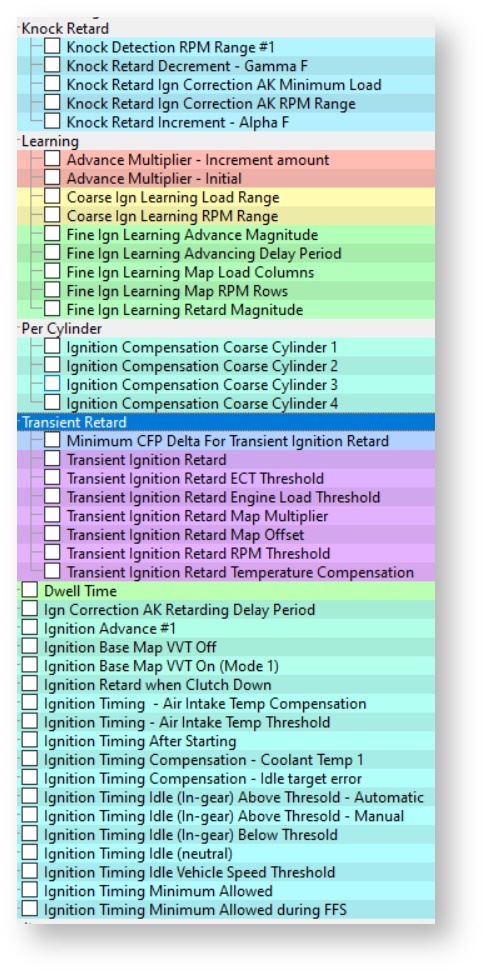
Knock Detection RPM Range
The engine RPM range in which the ECU is allowed to retard the ignition timing when the engine is knocking.
Knock Retard Decrement – Gamma F
This value controls the amount of timing cumulatively removed when each knock event is triggered.
Knock Retard Increment – Alpha F
This is the amount of timing cumulatively added when the ECU restores timing after a knock event.
Fine Ign Learning Advance Magnitude
The size of ignition learning advances after each 'Fine Ignition Learning Advance Time Interval'.
Fine Ign Learning Retard Magnitude
The size of ignition learning retards each time knock is detected.
Transient Ignition Retard
This map specifies the amount of timing to be removed during transient condition. The later ZA1JA01* and onwards have a serious map adjustment to help avoid transient knocking that has historically damaged DI combustion chamber seals. Base your tuning on the later A01 or B series ROMs.
Transient Ignition Retard RPM Threshold
Specifies the Engine Speed range under which Transient Ignition retard will be active. Make sure this is set at 8000+RPM.
Minimum CFP Delta for Transient Ignition Retard
Specifies the minimum change in Cylinder Fill Percentage for the transient ignition retard to be applied.
Transient Ignition Retard ECT Threshold
Specifies the minimum ECT for transient ignition retard activation.
Transient Ignition Retard Engine Load Threshold
Specifies the minimum Engine Load for transient ignition retard activation.
Transient Ignition Retard Temperature Compensation
This provides a multiplication factor for transient ignition retard for ECT.
Catalyst Warm-up Retard Drive & Idle
Ignition timing retard amount for a given coolant temperature and engine load. This can be used to speed up the heating of a catalytic convertor after starting from cold.
Map List
Live Data Parameters
- Ignition Timing (Deg) – Displays the current Ignition Timing.
- Ignition Correction – Coarse – Shows the output of the Ignition Advance map multiplied by the current Advance Multiplier Value. If the Advance Multiplier value is 1 then the logging parameter will match the Ignition Advance map value (and the full value from the Advance Map is added to the Ignition Base map value). If the Advance Multiplier is 0.5 then the logging parameter will only be 50% of the Ignition Advance map value (and only 50% from the Advance Map is added to the Ignition Base map.
- Ignition correction – Fine -This is the Learned Knock Retard in the ECU’s Memory.
- Knock Correction – This displays the Knock Correction Amount
- Knock Correction Learn Value – This is the Ignition Correction Coarse minus the Ignition Correction Fine value.
"Mode" refers to the map slot you are on. "Mode 1" being the base one used if not utilizing the map switching feature
Limiters
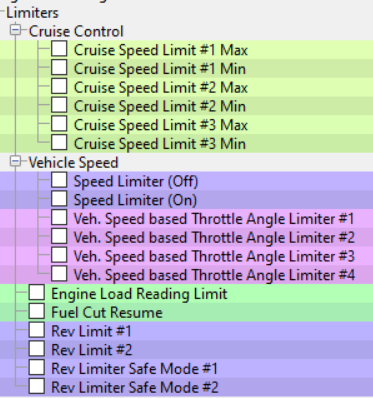
Speed Limiter – On & Off
This controls the vehicle speed that the fuel injectors will be cut to maintain a set vehicle speed or restored when the vehicle has decelerated.
Vehicle Speed based Throttle Angle Limiter #1 - #4
These maps control the maximum allowed throttle opening for a set Engine Speed. Either raise the values in the axis. Do NOT adjust the right hand side of these maps just adjust the left hand column with the vehicle speed shown.
Mass Air Flow Reading Limit
This is the maximum Mass Air Flow that the ECU will use. If your engine exceeds this value the ECU will incorrectly calculate engine load which means all the ignition and fuel maps will be inaccurate and the fueling will be very lean at high RPM. This map is often overlooked so please ensure you raise the values.
Rev Limit #1 and #2
This controls the engine speed that the fuel injectors will be cut to maintain a set RPM. The second value in each map is the hysteresis and is the Engine Speed when the injectors will restore.
Fuel Cut Resume
This is the manifold pressure at which the engine will restore the injectors after a fuel cut.
Engine Load Reading Limit
Engine Load Max Limit, this must be raised if your Engine Load exceeds this value.
Map List
Live Data Parameters
Load
Engine Load Limiter #1 & #2
This is the maximum value of engine load that will be used in the ECU. If your engine load exceeds this value then the engine will run lean and advanced, these values should be raised especially with forced induction setups.
Calculated Engine Load Compensation #1 / #2
Calculated Engine Load Compensation factor based against MAP, used to correct Airflow/Engine Load as required. This map can also be used to correct Fuel Injector open time A/F Correction #1 errors at light load.
Calculated Cylinder Fill Percentage
Used internally by the ECU to calculate the amount of cylinder fill per stroke (CFP), as the engine has a large throttle butterfly then the maximum cylinder fill can be achieved at low RPM and small throttle opening (relatively low airflow). There is no need to adjust this map.
Engine Load Multiplier and Atmo Pressure compensation
These are used internally by the ECU and there should be no need to adjust these values.
Map List
Live Data Parameters
- Engine Load (%)
- Mass Air flow (g/s)
Sensor Scaling
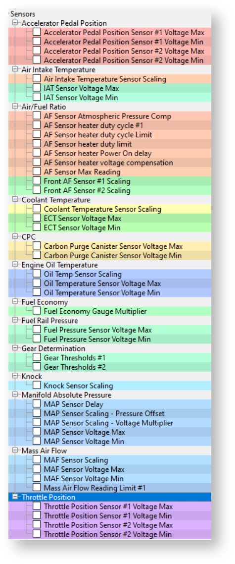
AF Sensor heater duty limit
The maximum allowed AF sensor heater duty
Atmospheric Pressure Sensor Scaling Pressure Offset & Voltage Multiplier
This is an offset and multiplier sensor scaling. If you change the atmospheric pressure sensor on your vehicle please consult the manufacturer documentation for the correct values.
For information on how to re-scale the factory or aftermarket Manifold Absolute Pressure sensors, Refer to our guide BRZ: MAP Sensor Re-scaling
MAP Sensor Scaling – Pressure Offset
Manifold pressure sensor offset. Value is measured in bar.
MAP Sensor Scaling – Voltage Multiplier
Manifold Pressure Sensor multiplier in bar per volt.
Atmo Sensor Scaling – Pressure Offset
Atmospheric pressure sensor offset. Value is measured in bar.
Atmo Sensor Scaling – Voltage Multiplier
Atmospheric pressure Sensor multiplier in bar per volt.
Mass Air Flow Sensor Scaling
This map can be used to rescale the Mass Air Flow sensor relation between voltage and Mass Air Flow in g/s. Change this value if you have changed the MAF housing or intake system of if your AFR does not match what’s in your fuel map. For more information check out our guide BRZ/FRS/86/DIT WRX: How to Re-scale your MAF for Intake/Induction Changes
Air Intake Temperature Sensor Scaling
This map can be used to rescale the intake air temperature sensor voltage to temperature scaling.
Coolant Temperature Sensor Scaling
This map can be used to rescale the coolant temperature sensor voltage to temperature scaling.
Map List
Live Data Parameters
- Coolant Temp
- Air Temp
- Mass Air Flow
- Engine Oil Temperature
- AFR
- AFR Sensor
Misc.
Radiator Fan Control
Shows the coolant thresholds where the each fan will switch ON and OFF, in our testing Rad Fan Threshold #1 maps are used, Threshold #2 maps may be used in different conditions so make a log file to verify your results like vehicle speed and with or without AC.
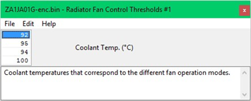
3rd Value (94deg C) is FAN No.1 ON
1st Value (92deg C) is FAN No.1 OFF
4th Value (100deg C) is FAN No.2 ON
2nd Value (95deg C) is FAN No.2 OFF
Gear Thresholds #1 & #2
The values are used to calculate the current gear position. The values are kmph for 1000 RPM. E.g in first gear, if the value is 10.5 then it would mean your speedometer displays 10.5kmph at 1000RPM on the tachometer. Change these maps if you have different ratio gears in your gearbox than the standard vehicle.
Diagnostic Trouble Codes & DTC Limits
This can be used to turn off any DTCs like catalyst efficiency and fuel tank pressure sensors.
Disabling DTCs should be done with care and understanding.
Example, if you disconnect the coolant sensor the engine will default to a 75 deg C coolant temp and run quite well, if your turn off the Coolant temp DTC then the ECU will use the Coolant temp sensor input and assume -40 deg C !
There are also DTC limits which control when the different DTCs are set.
DTC Enable Table
Enables/Disables the DTC from showing, the codes are listed here: BRZ/FRS/GT86 DTC Codes
DTC Limits
The Min and Max thresholds where certain DTCs are tripped. You may need to raise or lower certain sensor limits like MAF Sensor MAX Voltage on a Forced Induction model or lower the MAP Sensor MIN Voltage when you fit a 3 or 4bar MAP sensor
P0301 misfire detection
Misfire detection causing P0301 DTC.
Number in map is misfire counts in 200 revolutions.
Map List
Live Data Parameters
EcuTek ProECU tuning tools tools should only be used by experienced tuners who understand the product and engine calibration.
If you do not fully understand this product then you WILL damage your engine, ECU or your vehicle.
Please ensure you fully read all EcuTek manuals BEFORE attempting to use ProECU with your laptop or your vehicle.
Use with extreme caution and understanding at all times, if in doubt then do not proceed.
EcuTek accepts no responsibility for any damage to the engine, ECU or any part of the vehicle that results directly or indirectly from using the product.
** If you are in any doubt that you do NOT have the experienced required to use this product then you should NOT USE IT **
Retail customers
** If you have any doubt that you do NOT have the experienced required to use this product then you should NOT USE IT, you should simply contact your EcuTek Master Tuner shown clearly on the top of your Programming Kit or visit your preferred tuning shop to have a professional tuner to use it for you **