Speed Density
The Speed Density feature changes the way that mass airflow is calculated. When SD mode is activated, the ECU will disregard the MAF sensor reading and calculate mass airflow based on Engine Speed, Manifold Pressure and Air Temperature instead. This allows you to remove the MAF sensor and fit a larger intake if desired.
The Speed Density feature is enabled by selecting the checkbox in the Speed Density Enable map.
The Speed Density Feature can be enabled in any of the three calibration modes by selecting the appropriate checkboxes in the Enable Speed Density (SD) map.
When this feature is active, the ECU will ignore the reading from the Mass Airflow sensor and will calculate mass airflow as follows: Estimated mass airflow is calculated from RPM, Manifold Pressure, Charge Air Temperature, and VE (read from the Speed Density Volumetric Efficiency map)
It is expected that this feature will be used in applications where you wish to replace the MAF sensor with a custom intake. If you remove the MAF sensor, you must go to the “Enabled Diagnostic Trouble Codes” map and tweak items relatedto MAF sensor errors. If you do not then the ECU will detect a “Mass Airflow sensor failure” and use its fallback processing instead of the Speed Density feature.
Using Speed Density and MAF sensor together
The Speed Density feature can also be useful in applications where the MAF sensor is present, but the amount of airflow is higher than the MAF sensor can measure. In this scenario, the ECU can be programmed to use the MAF sensor at lower mass airflow values and switch to Speed Density for the higher values.
You can specify threshold values of MAF, RPM and MAP that are required for Speed Density activation. The ECU will activate the Speed Density feature only when all three of these values are above their respective thresholds.
The threshold values are implemented using hysteresis. The 1st value should be higher than the 2nd value. The feature will activate when the parameter rises above the 1st value, and will deactivate when it falls below the 2nd value.
You can also use the Speed Density feature in applications where the amount of airflow is lower than the MAF sensor can accurately measure. In this situation, enable the “Activate BELOW thresholds instead of ABOVE” checkbox. The ECU will activate the Speed Density feature when MAF, RPM and MAP are all below their respective thresholds.
The default value for the thresholds is zero. If you use the “Activate BELOW thresholds instead of ABOVE” checkbox, then the feature will only be activated when all three parameters are below their respective thresholds. Therefore you need to set a high value into any thresholds that you are not using, otherwise the feature will not activate.
Integration with Map Switching Feature
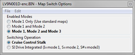
Speed density can be enabled in each of the three map switch modes. There is only one set of speed density maps. If you require separate speed density maps for each mode, use the custom maps feature to apply adjustments to the base map depending on which mode is selected.


