Subaru DIT Tuning Guide
- Brandyn Mowat
- Lucan Hetherington

ProECU Tuning Guide
Introduction
This FA20 DIT variant is based on the current Subaru BRZ, Scion FR-S and Toyota GT86 engine, but unlike the BRZ/FA20 engine that used a Toyota based Port and Direct injection system, the new DIT uses
Subaru’s own DI system, developed by Hitachi. This new DI system is also found on the Nissan Juke 1.6 DiG Turbo model that ProECU already supports.
The 2.0ltr DIT engine is found in the following models:
Legacy GT – 300bhp (Japan only)
Forester XT – 240bhp (Euro, Australia and USA)
WRX – 260bhp (Australia, USA, Russia and Asia)
Levorg 1.6L
All of the above are CVT transmission models apart from the WRX which is available with a manual gearbox option.
The ProECU DIT tuning suite supports all models from all regions with high speed programming and high speed datalogging and includes the typical ProECU features available in other tuning suites. ProECU also includes an ECU Recovery feature in the event of a programming failure.
Supplemental Content
Platform Specific
General
Table of Contents
Accelerator, Torque and Throttle
When increasing the boost pressure the torque generated will be higher, if the torque value is too high the ‘Proportion of Max Torque’ can be too high and this can lead to the throttle closing during a power run like shown below. The Desired and Actual Torque can be difficult to cross reference and calculate especially with the added complication of the Wide Open Throttle Torque threshold map that profiles the boost and airflow relationship to the throttle opening angle.
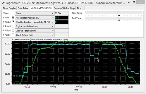

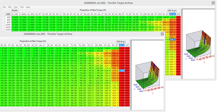
In the latest RRFF there is a new logging parameter called ‘Torque Proportion of Max’, this will show the X axis of the ‘Throttle Target Airflow’ map. When the throttle closes you will see that the new logging parameter will drop below 100% and that the factory setting for the map called Throttle Target Airflow will output a reduced Mass Airflow value resulting in the throttle butterfly closing. The easiest and most simple way to avoid this annoying issue is to move the values in the map 1 or two cells to the left like shown below, this will keep the throttle open if the Proportion Of Max Torque drops below 100% for any reason.
In this particular example below the 2d map called ‘Wide Open Throttle to Torque’ is filled with 200NM (for example purpose only), this will mean we will have full throttle opening at 200Nm Torque Demand. This is also 100% Torque Proportion of Maximum (logging parameter). So you can see that the yellow line shows 100% as soon as the red line (Torque Demand) hit 200Nm, this is also the point when the cyan line (throttle opening angle) is fully open.
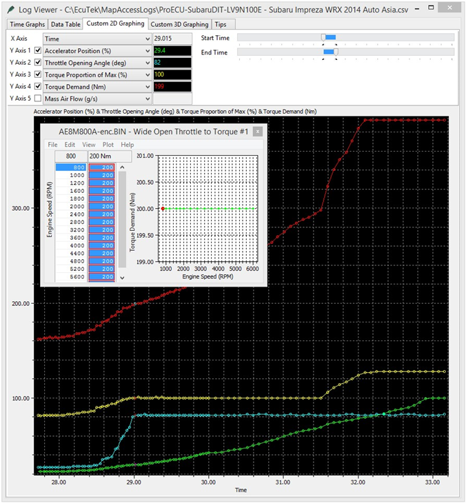
You can see as the Accel pedal (green line) is pushed further and even more torque is demanded that at 300Nm the Torque Proportion of Maximum increases even further to 128% though the throttle butterfly can physically open no further than 82 degrees.
The reason it starts to climb again at 300Nm is not known at this time, there may be and additional threshold but it’s not really relevant as the throttle is already fully open. Though this is probably linked to the closed loop boost control that uses engine torque calculations.
If the throttle angle reduces during a pull through the rpm range then copy and paste the values on the right hand side of the map called Throttle Target Airflow one or two cells to the left, see the throttle tuning section for further information.
Map List
Live Data Parameters
- Desired Torque (requires RaceROM)
- Torque Proportion of Max (requires RaceROM)
- Accelerator Position - Relative
- Throttle Opening Angle
- Throttle Position - Relative
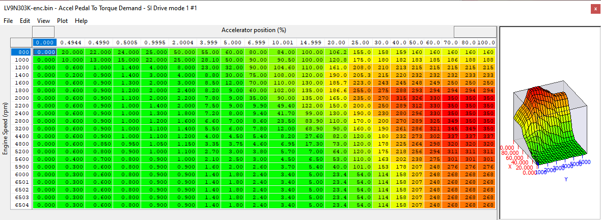
Accel Pedal to Desired Torque
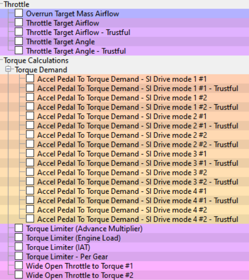
These maps define the desired engine torque output for a set Engine Speed and Accelerator position. There is one map for each SI Drive mode, when SI Drive is not fitted then the 2nd map is normally used. If you alter an Accel Pedal to Desired Torque map then ensure you set the corresponding Trustful map the same.
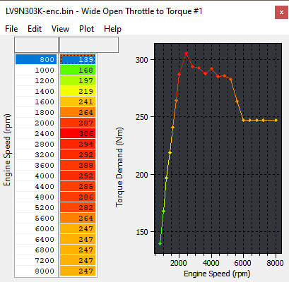
Wide Open Throttle to Torque
This map is used to calculate the percentage of maximum torque. When the driver torque demand reaches this torque threshold (in Nm) then the throttle butterfly will be fully open. Raising these values could stop you from achieving full throttle butterfly opening.
Reducing these values would mean the throttle butterfly would be open further for the same accelerator position (Torque Demand amount). Ensure both maps are set the same.
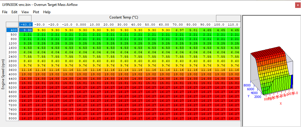
Overrun Target Mass Airflow
This is the target mass airflow during gear change and deceleration. This map can cause the rev hang issue found on the manual gearbox WRX models. Reducing these values will reduce the rev hang issue on WRX and will increase engine braking during lift-off (deceleration).
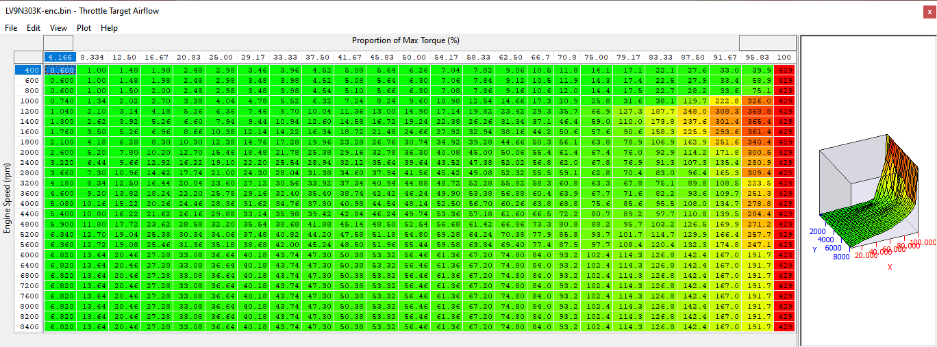
Throttle Target Airflow (inc Trustful)
The throttle target airflow for a given desired torque. The desired torque is expressed as a percentage of the maximum torque obtained at wide open throttle. Ensure the values in this map are pasted into the corresponding Trustful map.
This map can cause the throttle to close during power runs, see the tuning section for guidance on this issue.
Please also see the "Wide Open Throttle to Torque" map and “Throttle Target Angle”.
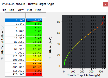
Throttle Target Angle
Converts the output of the map called “Throttle Target Airflow” to a final throttle angle. Increasing these values will provide a greater throttle opening angle for the given airflow.
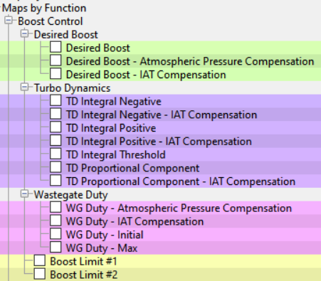
Boost Control
Desired Boost
This map controls the amount of boost pressure that the ECU tries to achieve, based on RPM and desired torque (Nm). The pressure is in bar absolute. You can simply increase the target boost required for a given RPM and torque and the boost pressure will increase (assuming the wastegate duty can achieve the boost required). It is wise to tail off boost at high RPMs to preserve engine reliability.
Map List
Live Data Parameters
- Atmospheric Pressure
- Charge Air Temperature
- Wastegate Duty Cycle
- Intake Air Temp
- Manifold Absolute Pressure
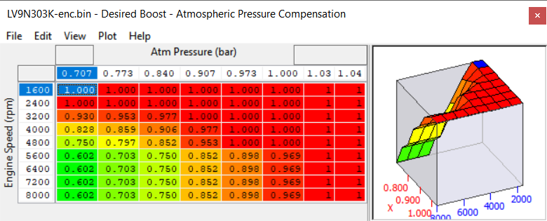
Desired Boost - Atmospheric pressure Compensation
Controls how desired boost pressure is scaled depending on the current atmospheric pressure. See that the boost target is reduced even at sea level at higher RPM.
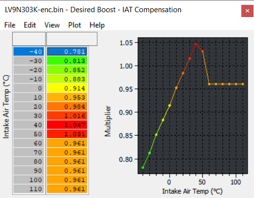
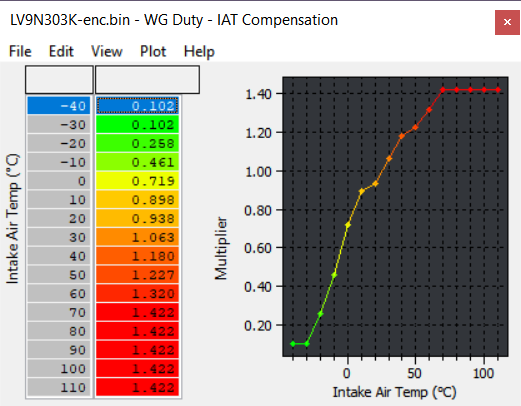
Desired Boost - IAT Compensation
Controls how desired boost pressure is altered depending on the intake air temperature.
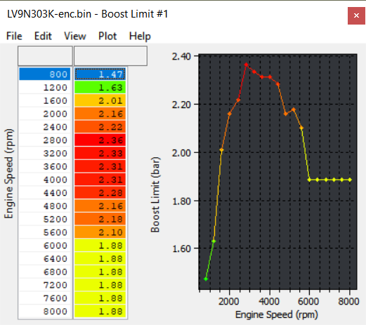
Boost Limit
Determines the boost limit based on the engine RPM.
If the boost limiting is triggered, fuel cut will occur to protect the engine.
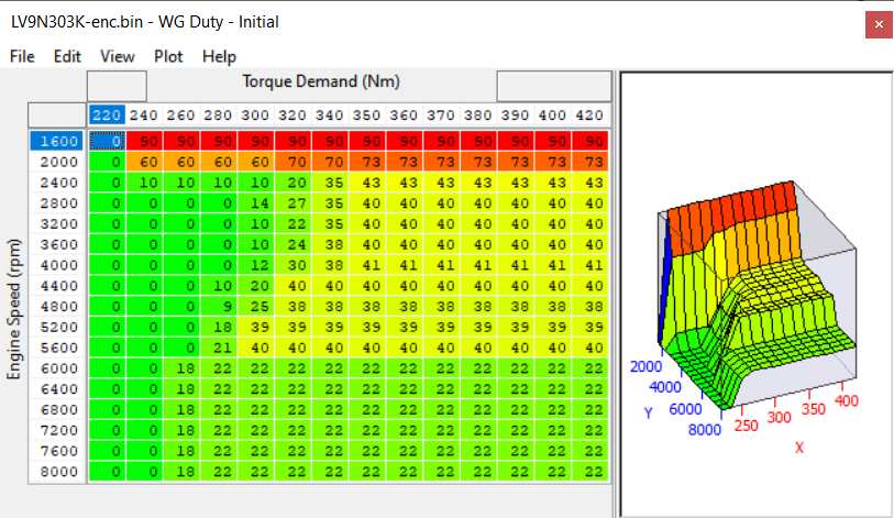
Initial Wastegate Duty
The initial duty cycle values to achieve ‘Desired Boost’. This map references both RPM and desired torque (Nm). The wastegate duty chosen from this map is then altered by compensation maps for atmospheric pressure, temperature and turbo dynamics, before being applied to the actuator. It is recommended that the Wastegate Initial map values are always set about 10% below that of the corresponding Max Wastegate values. It can be helpful to use lesser duty cycles values as throttle position decreases to make the car ‘more linear’ in relation to throttle input (Be sure to scale all related maps accordingly).
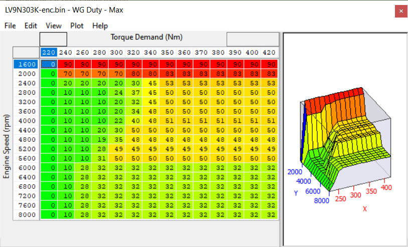
Maximum Wastegate Duty
This map controls the maximum wastegate duty that the ECU can use for a given RPM and throttle position. The values in this map must be great enough to permit the required boost to be achieved, but low enough so as not to allow overboost to occur.
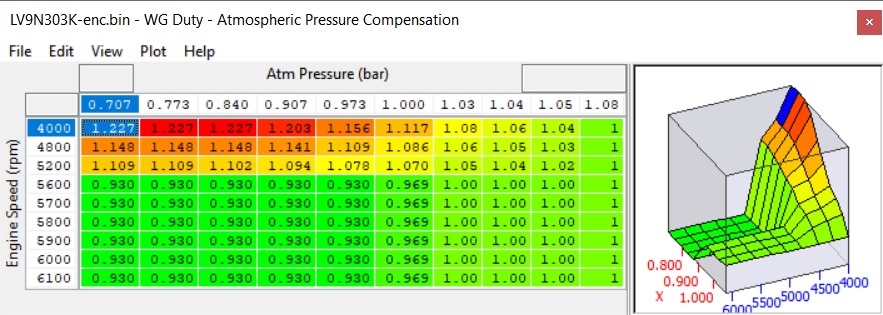
Wastegate Duty - Atmospheric Pressure Compensation
Controls how the duty cycle is scaled, according to the current atmospheric pressure. At high atmospheric pressures, it is easier for the turbo to build boost, since the air it is compressing is denser. This means that a lower duty cycle is required at sea level for example, when compared with higher altitudes, in order to achieve the same boost pressure. The turbo’s are also very small and easily over speeded so the Desired Boost and WG Duty will often be reduced at high altitude to protect the maximum turbo speed that is achieved. See that the WG Duty is reduced even at sea level at higher RPM.
Wastegate Duty - IAT Compensation
Controls how the duty cycle is scaled according to the intake air temperature. At low temperatures the air is more dense. As such less wastegate (and thus a lower duty cycle) is required in order to produce a given level of boost.
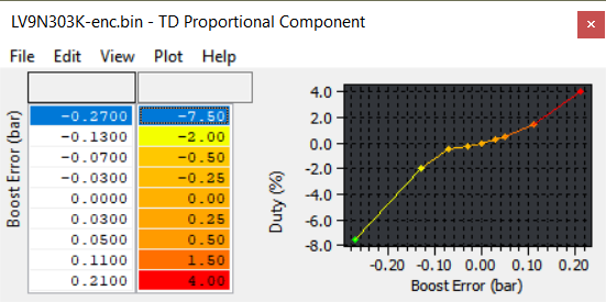
Proportional Component
Initial values of compensation are taken from this map to give a burst of duty when stamping on the throttle for example. Larger values can be helpful for increasing the response with larger turbochargers.
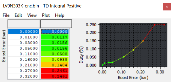
Integral Positive & Negative
These maps add or subtract duty cycle depending on how long the boost error has persisted for, as well as how large the error is. The values in these maps are small, but help to maintain faster responding control of boost. Also, there may be two integral maps, split into positive and negative regions. One is used when boost is too high (the negative compensation map); the other is used when boost is too low (the positive compensation map). When using a different turbocharger or more boost, it may be helpful to modify these maps to achieve proper boost correction without surging.
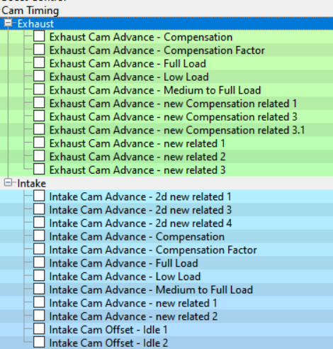
Camshaft Timing
Cam Control
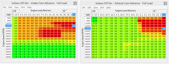
There are 3 maps to control the intake and exhaust cams.
Which map is chosen depends on the way the driver demands engine torque and the speed at which the engine load changes. When gently pressing the accelerator pedal the Low Load map will be used, when quickly flooring the pedal the Full Load map will be used.
Always make sure the Inlet and Exhaust VVT is working!! After starting the engine the Exhaust cam takes some time to become active, up to 30 seconds. If a power test is made whilst the Exhaust VVT is not active then a significant amount of power and torque will be lost. After starting, allow the vehicle to Idle for 20-30 seconds until Closed Loop is achieved and Fuel Trim Short Term becomes active, then gently lift the RPM and watch the Exhaust VVT angle in the LIVE DATA window, once it starts to move then you can make your tests. If working on a dyno a short cruise at low speed then letting it slow down to a stop and allow it to idle should enable the VVT every time.
Intake Cams
- Intake Cam Advance Low Load* – This map is used at Light Load conditions for low emissions and good fuel consumption.
- Intake Cam Advance Medium to Full Load – This map is used during normal driving conditions and is continued to be used on Full Load as long as smooth and progressive throttle is applied.
- Intake Cam Advance Full Load – This map is used when a sudden high torque demand is made by the driver by aggressive movements of the Accel pedal.
Exhaust Cams
- Exhaust Cam Advance Low Load* – This map is used at Light Load conditions for low emissions and good fuel consumption.
- Exhaust Cam Advance Medium to Full Load – This map is used during normal driving conditions and is continued to be used on Full Load as long as smooth and progressive throttle is applied.
- Exhaust Cam Advance Full Load – This map is used when a sudden high torque demand is made by the driver by aggressive movements of the Accel pedal.
* If using full time Speed Density then the Low Load maps should be set the same as the other two maps
Cam Compensation maps
Inlet and Exhaust Cam compensation maps are used to change the cam target for a given coolant temperature, on the WRX this will reduce the Exhaust Cam overlap when the engine is cold. The Inlet maps have not been calibrated at this time.
Cam Tuning for Power and Speed Density
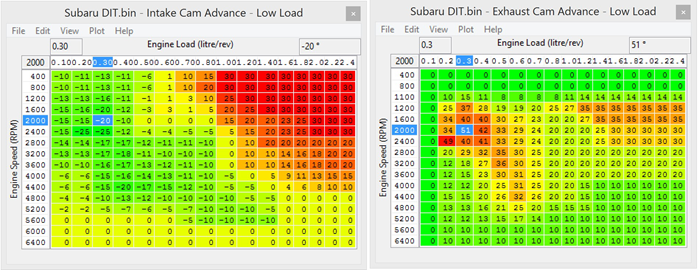
As seen below the ‘Low Load’ maps have significant overlap at light load and low RPM which reduces cylinder fill but also forces spent exhaust gas to be pushed into the Inlet port, this is known as internal EGR and is designed to reduce emissions.
But this exaggerated cam overlap will reduce the manifold depression in the plenum/inlet manifold, this causes problems when running on Speed Density as SD is a Manifold Pressure based calculation and Engine Load will be higher than it should be causing rich AFR and retarded Ignition Timing.
So when using Speed Density at light load/low rpm (or full time SD) the ‘Intake Cam Advance – Low Load’ map values should be set the same as ‘Full Load’ or ‘Medium to Full Load’ Cam Advance maps, this prevents the ECU from entering light load emission phase cycle (instigating Internal EGR) which will cause problems when running on SD.
Tuning for more power, when the accel pedal is moved quickly (immediate high torque request) the ECU will switch to the ‘Full Load’ cam maps, these have been profiled to provide maximum torque as quickly as possible. You can see from the Intake and Exhaust profiles below that significant advance is used to encourage turbo spool. Raising and extending this values will produce more aggressive spool (increased torque) though dyno testing is required to prove the best results.
The boost pressure should be watched closely as it’s possible to spool the turbo more quickly (using cam overlap) by allowing the Inlet turbo pressure through the cylinder into the exhaust manifold which will decrease turbo lag but it will not actually produce more torque (as the boost is not in the cylinder but in the exhaust manifold!).
Map List
Live Data Parameters
- VVT Intake Advance Angle Amount L and R
- VVT Exhaust Retard Angle L and R
- OCV Intake Duty L and R
- OCV Exhaust Duty L and R
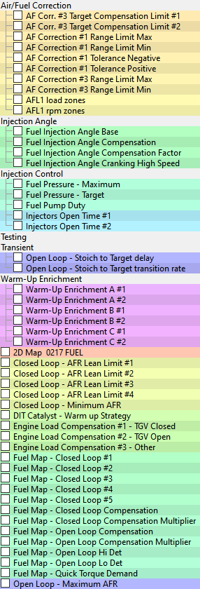
Fuelling
At this time the main limiting factor of the system seems to be the amount of Direct Injection pump flow possible. Unlike other DI fuel systems it seems we cannot get significant increase in fuel pressure (or more importantly fuel volume) delivery from the stock fuel pump, this will be OK on lesser power models like FXT and WRX but the LGT at 300PS from the factory will be limited in the future. Our current calculations show the DI pump can only supply enough fuel for around 340bhp.
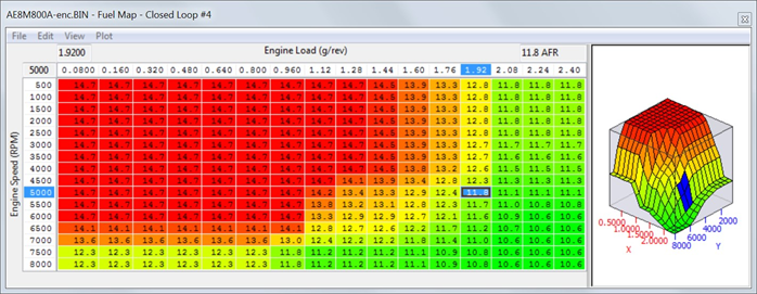
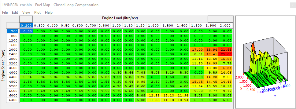
Fuel Maps – Closed Loop
Closed loop #1 - #5
These maps are used when the engine is in Closed Loop and the Fuel Trim Short Term (FTST) correction is active. These maps are used at light load and also on full load and it should be noted that the Closed Loop value does not have to be 14.7:1 AFR. If the Closed Loop target AFR value is 13.5:1 or even 12:1 AFR then the ECU will maintain Closed Loop control using the FTST.
There are up to 5 Closed Loop target maps (depending on the exact ROM version) but the exact condition that the ECU switches between the maps is currently unknown.
Closed Loop #4 is used most of the time but the ECU seems to step and interpolate between these maps so use with caution and understanding.
Map List
Live Data Parameters
- A/F Target
- A/F Sensor
- Fuel Trim Long Term
- Fuel Trim Short Term
- Engine Load (g/rev requires RaceROM)
- Mass Air Flow
- Fuel Injection Pulse Width
- Fuel Pressure - Target
- Fuel Pressure - Gauge
- Fuel Pump Duty
- Fuel Injection End to Spark
- Fuel Injection Angle
Closed Loop Compensation
This map isn't found in all ROMS
This AFR Enrichment factor is added depending on the current AM (Advance Multiplier). The weighting factor of how it’s applied for a certain AM can be calibrated in the following map.
The compensation map is profiled so when the AM reduces (engine knocking) then the AFR will become richer in the areas where the engine is most susceptible to detonation (like at peak torque).
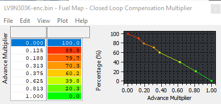
Closed Loop Compensation Multiplier
This map isn't found in all ROMS
This is the percentage ratio of the Fuel Map – Closed Loop Compensation that is added to the Fuel Map – Closed Loop for a given AM.
On vehicles where this map doesn't exist, the entire map value is added when the advance multiplier is at 0. If the Advance Multiplier is at 1, 0% of the map is added. Intermediate AM values will add a partial enrichment. When AM is .7, 30% of the map value is added etc.
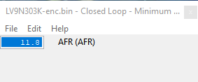
Closed Loop – Minimum AFR
This Minimum AFR value for Closed Loop. If the desired value in the Closed Loop fuel map is below this value, the ECM will switch to Open Loop and use the Open Loop fuel map instead.
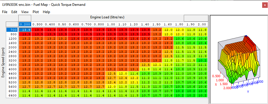
Quick Torque Demand
This Closed Loop target AFR map is selected when the Accel pedal is depressed very quickly (where the driver is demanding a sudden and immediate increase in engine torque and acceleration). This map is used in a Closed Loop condition. The ECU is entering a special ‘Hi Torque’ mode and this condition is also reflected in the VVT maps that are chosen. The map is used in closed loop regardless of the AFR target values in the
‘Fuel Map - Open Loop’. The ECU will stay in the mode until the Accel pedal is released and the normal engine control strategy is resumed.
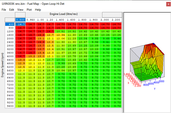
Open Loop Hi Det
This map is used when the engine is knocking hard and continuously and a richer AFR is required to reduce knock and reduce cylinder temps.
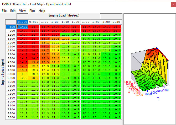
Open Loop Lo Det
This map is used under normal running and the AFR values chosen are used in an open Loop control condition.
Open Loop Compensation*
This AFR Enrichment factor is added depending on the current AM (Advance Multiplier). The weighting factor of how it’s applied for a certain AM can be calibrated in the following map.
The compensation map is profiled so when the AM reduces (engine knocking) then the AFR will become richer in the areas where the engine is most susceptible to detonation (like at peak torque).
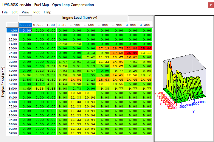
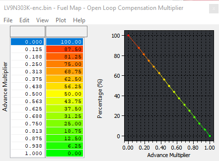
Open Loop Compensation Multiplier
This map does not exist in all ROMS
This is the percentage ratio of the Fuel Map – Open Loop Compensation that is added to the Fuel Map – Open Loop Lo Det for a given AM. If this map doesn’t exist in a particular ROM, the ECU works in the following way:
On vehicles where this map doesn't exist, the entire map value is added when the advance multiplier is at 0. If the Advance Multiplier is at 1, 0% of the map is added. Intermediate AM values will add a partial enrichment. When AM is .7, 30% of the map value is added etc.
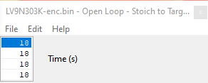
Open Loop – Stoich to Target delay
The time period required to decay when the ECU will switch from Closed to Open Loop. This map should always be filled with 0 so there is no time delay when transitioning from a Closed Loop to an Open Loop condition.
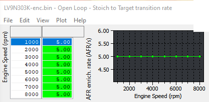
Open Loop – Stoich to Target transition rate
This map should be filled with the maximum allowed value of 1000 so the step amount during Closed to Open Loop is as fast as possible and there is no delay in the transition between the two modes. Setting this map to zero would mean the transition from Closed to Open Loop would take a very long time and remember the AFR during transition is leaner than 14:1 AFR!!!
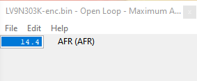
Open Loop – Maximum AFR
The Maximum AFR value for Open Loop.
If the desired value in the Open Loop fuel map is higher than this value, the ECM will use this target value instead.
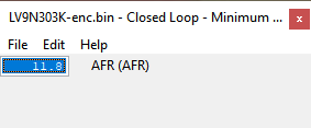
Closed Loop – Minimum AFR
The Minimum AFR value for Closed Loop. If the desired value in the Closed Loop fuel maps is below this value, the ECM will switch to Open Loop and use the Open Loop fuel map instead. This may be set to zero in some region ROMs so this strategy is not used.
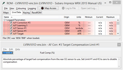
Fuel Trims
The ECU may use Fuel Trim Long Term in open loop, this can causes serious problems for the full load AFR over a period of time. The rear o2 sensor fuel trims are called AF Correction #3 by Subaru and they should be disabled in open loop, simply set the values to zero as shown below
(WRX only). Legacy and Forester use the map called ‘Closed Loop – Rear O2 sensor compensation’ this should be unchecked if the Rear O2 is used for other purposes on these models.
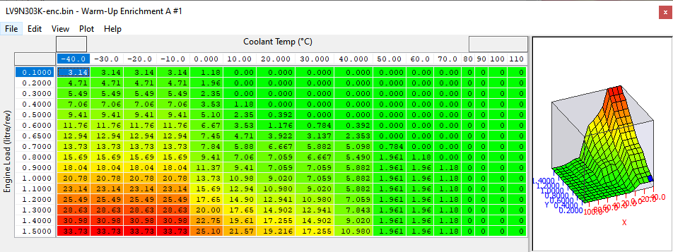
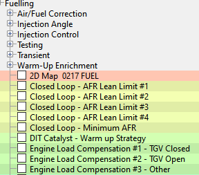
Warm-Up Enrichment
These maps provide an enrichment factory during warm up (after starting), if a greater volume of fuel is required during this post start period and before closed loop fuel control kicks in then these maps can be adjusted. Its subjected that all enrichment maps should be adjusted by a percentage.
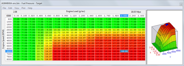
Fuel Pressure - Target
This is the target pressure for the fuel rail, this is a mechanical pump and it has limitations for what it can deliver. The units are MPa and 18MPa is 180bar so take care when working with the DI system. Our testing has shown that the stock fuel pump can only supply enough fuel for around 340 to 350bhp (depending on AFR). Beyond this a high pressure high flow fuel pump will need to be fitted. Demanding a higher pressure will not automatically mean the mechanical pump can deliver it.
Fuel Pressure - Maximum
This is the maximum allowed fuel pressure target in MPa, these values can be increased slightly to deliver more fuel but ultimately the high pressure fuel pump is serious limited by the additional fuel volume that it can deliver per pump revolution.
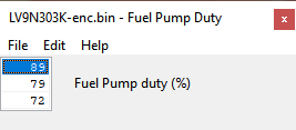
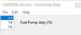
Fuel Pump Duty
The fuel pressure duty cycles set for the primary lift pump – No need to alter these settings unless a larger high pressure and low pressure pump has been fitted.
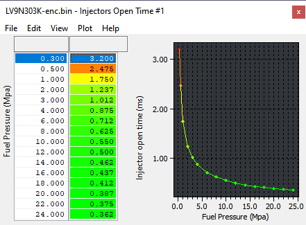
Direct Injector Open Time – Fuel Pressure
This is the Direct Injector (DI) open time period for a given fuel pressure. Increasing these values by a set percentage (%) will directly open the DI for a longer period. This map can be used as the DI multiplier for Ethanol tuning.
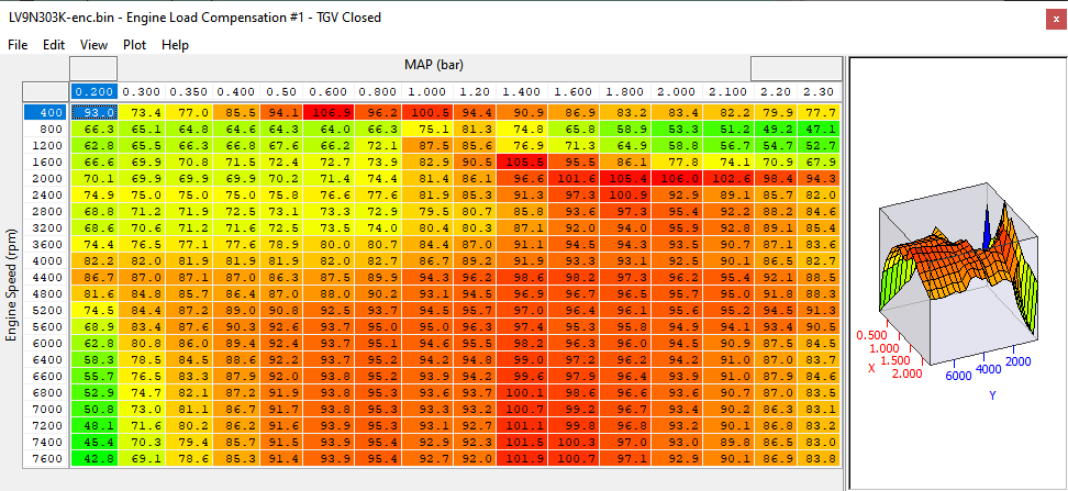
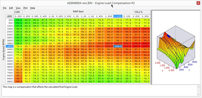
Engine Load Compensation #1 - #2
These 3d maps are used a part of a volumetric efficiency calculation to correct the engine load in certain condition, its particular noticeable in map #1 when TGV is closed and there is a lot of valve overlap at light load when compared to light load high RPM.
Increasing or decreasing the map values will directly affect Engine Load, Ignition Timing and Injector open time but it does not affect the Mass airflow (as shown in the mass airflow logging parameter). See the tuning section for more information
Adjusting the Direct Injector Firing Angle
The Direct Injector Angle map (called Fuel Injection Angle Base) shows the Start Of Injection (SOI) angle in crankshaft degrees before TDC (spark plug firing).
This will be followed by the End Of Injection (EOI) when the Direct Injector will actually close. The time period that the DI is actually open for is controlled by the Fuel Map Target AFR and how much fuel volume is required to achieve that AFR for a given fuel pressure.
The Fuel Injection Angle map shows the SOI angle is crank degrees before TDC spark firing (not TDC valve overlap).
- 180 deg will mean SOI will commence at BDC (end of the Induction stroke and start of the Compression stroke).
- 270 deg will mean SOI will commence half way down the Induction stroke with the piston heading down for BDC.
- 360 deg will mean SOI will commence at TDC during Inlet and Exhaust valve overlap phase (the start of the Induction stroke and end of the Exhaust stroke).
There are four main logging parameters to consider here:
- Fuel Injection Advance – This is the crank angle (deg) before TDC (spark plug firing) that the DI will commence SOI.
- Fuel Injection #1 Pulse Width – the total time period is (ms) that the DI is open for.
- Fuel Injection End to Spark – This is the time period (ms) between the EOI and the spark plug firing (Ignition Timing), there must always be a time period between EOI and the spark plug firing.
As the DI can only inject during Induction and Compression strokes the total amount of DI open time is half of what a port injector could be (as port injectors can be open during all four strokes).
But the DI open time period is also limited by:
- Valve Overlap – If DI starts to early then the fuel could end up in the exhaust system.
- Ignition Timing – EOI must happen before the spark plug fires.
So valve overlap needs to be considered before the SOI, at high RPM (6000+rpm) you would expect to see the Direct Injection Angle (SOI) set at 340 to 370deg, this is during valve overlap but the piston is moving so fast that no fuel will travel into the exhaust system. In addition the Injection phase must be finished (EOI) before the spark plug fires, remember that the spark plug often fires BEFORE TDC and an Ignition Timing value of 25deg will mean the piston is still rising on the compression stroke when the plug fires so this limits the total time period that the Injector can actually inject. For tuning we need to be able to measure the time period left between EOI and the spark plug firing, this is the logging parameter called ‘Fuel Injection End to Spark’, this is the time period (ms) between EOI and the spark plug firing.
This is a very important logging parameter and it’s logged by default in the latest RRFF, monitor this closely whilst tuning. The actual DI open time is dynamic, the AFR Target is constantly changing due to closed loop control, fuel pressure and even knocking. The Ignition Timing is also dynamic with Advance Multiplier and Knocking Correction all affecting the final spark advance angle and limiting the available time period that the DI can inject for.
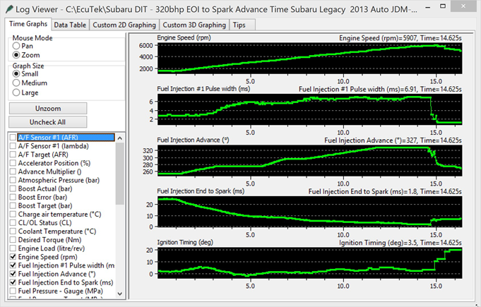
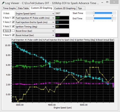
The two log file screen shots above show the ‘Fuel Injection Spark to End’ as 1.8ms at 6000rpm and the ‘Fuel Injection Pulse Width’ is open for 6.91ms, the DI firing angle at 327deg BTDC. So at 6000rpm the engine take 10ms for one revolution (5ms per stroke), so the maximum DI period (Fuel Injection Pulse Width) would be 10ms.
Allowing for valve overlap (DI angle at 327deg BTDC) and spark advance at 3.5deg BTDC then 10ms DI Open Time is simply not possible and we can see the free time between EOI and Ignition Timing firing is down to 1.8ms (Fuel Injection End to Spark logging parameter).
If the ‘Fuel Injection End to Spark’ time period is less than 0.5ms then misfiring will be experienced as the DI is open whilst the spark plug fires! This can also cause damage to the injector.
This logging parameter should never be less than 1ms in our opinion to give the fuel time to mix before the spark event. If more fuel is required then you can tweak several factors to increase this time period (though all have limiting factors):
- Increase Fuel Pressure by 1MPa so the Fuel Injector open time period (ms) will be less due to the higher demanded fuel pressure, the Fuel Pressure can only be increased by a small amount before the high pressure fuel pump is beyond capacity.
- Increase the Fuel Injector Angle map values at higher RPM which will start the injection period earlier (only at the RPM where there is no free time left), the SOI angle can only be pushed so far before it will inject fuel when the exhaust value is still open (though reducing the values in the Exhaust VVT map will means the Exhaust VVT closes earlier so less chance of fresh charge entering the exhaust.
- Lean the Fuel Map slightly which will reduce the DI open Time period though watch for knocking.
- Reduce Target Boost Pressure so less fuel injector open time is required.
Tweaking all of the above should ensure you have sufficient ‘free time period’ for maximum power.
Idle
Controlling the Idle speed of an engine is a difficult task and the factory ECU has many targets and compensations to achieve this. The Idle Target maps set the target Idle Speed for many different modes like drive, neutral, after starting, engine hot, load on (alternator or headlights etc). It is advised that you adjust all Idle maps by the same amount or simply set them all the same to avoid discrepancies in the idle engine speed.
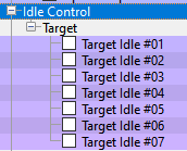
Target Idle
Desired engine idle speed for a given coolant temperature. If you wish to increase Idle Speed by 150rpm then add 150rpm to all Target Idle maps when coolant temp is over 50deg C.
Idle Stability Control
- axis is RPM idle error
- axis is rate of change of engine speed
This map is used for Idle Speed error compensation, making the values bigger will make the Idle Speed error more aggressive for correction.
Map List
Ignition
Advance and Timing Limits
The DIT runs very little timing advance compared to older STI models and even the more recent BRZ/ FR-S/86 models. Even with its lower 10.6:1 Compression Ratio the new DIT engine design does not allow us to run the sort of timing advance you would expect on a BRZ FI model or a STI so watch carefully.
The Intercooler seems particularly inefficient and you can watch the Charge Air Temp climb during a power run or pull on the road. Running a richer AFR will also help keep the engine quiet.
Timing Map Differences
In “Mode 1”, the ECU will use the original Base Ignition Timing and Ignition Advance map strategy labelled as TGV and VVT ON/OFF. In mode 2 and 3, the ECU will use the new singular RaceROM Ignition Timing and Ignition Advance maps labelled Mode2 and Mode3 respectively.
Ignition Timing Control
The Ignition control and dynamic advance system is very similar to older Subaru’s from 2005 to 2015. The DIT engine runs very little Igniting advance on full load compared to other Subaru’s like EJ25 or even the high compression BRZ/GT86 with a turbo fitted!
The DIT is very sensitive to Ignition timing and like most Subaru’s it runs on the edge of knock most of the time.
Spending time to understand the Ignition control is really important so you can understand what’s going on and make a good safe calibration.
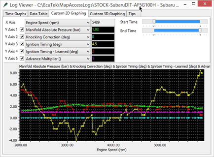
See the log file above, the Yellow line (Ignition Timing) is only 4.5deg BTDC at 5500rpm and the ignition timing is actually -4deg (ATDC) at peak torque. The knock control and fine learning are very active and can at times seem too sensitive. Charge air temp is again a significant and limiting factor and the factory Intercooler becomes saturated on two simple power runs. Charge Air Temps over 70deg C are not uncommon at higher RPM.
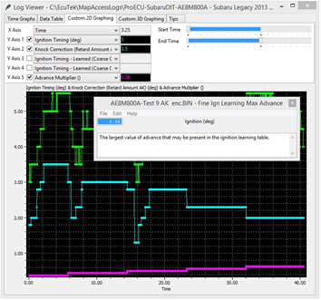
In this next example you can see the Fine Learning (Knock Correction Retard Amount AK) trying to advance the Ignition and raise the Advance Multiplier (down at only 0.38).
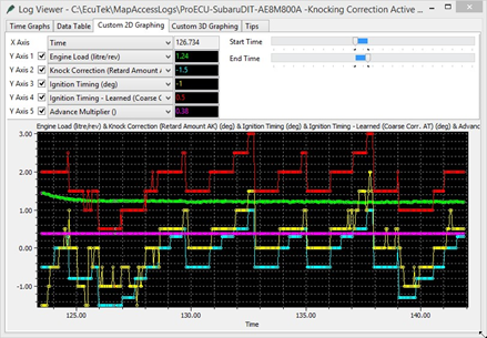
The Cyan coloured line shows AK cycling and building advance from -1.5 deg to a positive +1deg only to knock then start the cycle all over again.
You can also see the Red coloured line Ignition Timing Learned value (AT) increasing and decreasing as the Fine Learning is added and subtracted whilst exploring the knock limit.
In this next example you can see the engine is held on load, stead state and that the Advance Multiplier is climbing from 0.44 to 1 over a 70 second time period. You can see the Ignition Timing Learned (AT) also increasing from 3.5 to 7deg over the 1 minute period. Remember that AT is the output of the Ignition Advance map multiplied by the AM, so as the AM rises so does the Ignition Learned value. As a result the Ignition timing advanced from 5.5deg to 9deg.
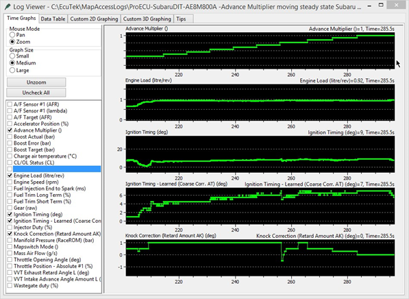
You can see that the Knock Correct (AK) value was positive (greater than zero) whilst the AM was climbing, this is the fine learning /dynamic advance working. AK adds positive advance and in the vent of no knocking the AM climbs.
Here are some facts to consider:
- The Ignition Advance maps are multiplied by the AM before being added to the Ignition base maps, so larger values in the Ign Adv maps will have a greater effect on the ignition timing when the AM changes, smaller values in the Ign Adv maps will have a smaller effect on the ignition timing when the AM changes.
- Different Knock Sensitivity maps will be selected relative to the Advance Multiplier (maps called Knock Sensitivity Ign Adv. Hysteresis and Threshold).
- On WRX the Ignition Advance Maps #1 and #2 are added together then added to the base map relative to the 2d maps called Ignition Advance – AM Factor #1/#2.
- Make sure that the actual Engine Load does not exceed the X axis Engine Load scaling on the Ignition maps, if it does then rescale all the Ignition maps.
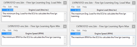
The thresholds above control the minimum and maximum Engine Speed (RPM) and Engine Load that the ECU is allowed to calculate and store the Fine Ignition Learning, these can be used to prevent the ECU from removing and stored Ignition Retard unnecessarily.
Ignition Base Map
The ECU selects an Ignition Base Map depending on the current VVT and TGV status:
- TGV Closed, VVT Off
- TGV Closed, VVT On
- TGV Open, VVT Off
- TGV Open, VVT On

Ignition Advance
The Ignition Advance map is added to the Ignition Base map relative to the LIVE DATA parameter called Advance Multiplier (AM). The Ignition Advance map is used as a coarse Ignition adjustment to advance and retard the Ignition timing for changing conditions like fuel quality, ambient temperature and altitude. On some models the Ignition Advance maps may be added together then added to the Ignition Base map so take care when adjusting these maps and watch carefully to understand the control.
The factory Ignition Advance map is calibrated to advance and retard the ignition timing by a greater degree in certain areas of the map (as seen in the next screen shot).
This is to ensure when the engine is knocking (and the AM decreases) that more Ignition timing is removed from areas where the engine is more susceptible to detonation (like peak torque). Areas where the engine is least likely to detonate the values are smaller (like light load).
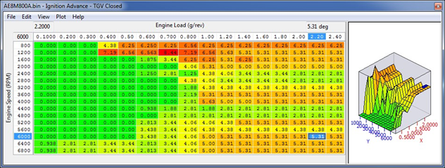
The X and Y axis scaling can be adjusted to suit higher RPM or higher Engine Loads if required.
The output of the Ignition Advance map is important and can be seen and logged in LIVE DATA as Ignition Timing Learned parameter.
So ‘for explanation purpose only’, if the Ignition Advance map was filled with 12 deg then the Ignition Timing Learned value would read 12 deg in LIVE DATA (assuming the AM is 1).
If the AM is 0.75 then the Knock Correction Learn Value would read 9 deg (12 * 0.75 = 9 deg). If the AM is 1 but the Ignition Timing Learned value is less than 12 deg at some points during a power run this indicates historical knocking events that have been Learned (see below for further information).
NOTE: In “Mode 1”, the ECU will use the original Base Ignition Timing and Ignition Advance map strategy labelled as TGV and VVT ON/OFF.
In mode 2 and 3, the ECU will use the new singular RaceROM Ignition Timing and Ignition Advance maps labelled Mode2 and Mode3 respectively. So the factory multiple Ignition control for different VVT/TGV conditions is not used in Mode 2 and Mode 3.
Any Ignition Timing Compensations for Air Temp or transient will still be included in the Ignition Timing compensation.
Advance Multiplier - Coarse Correction
The Advance Multiplier (AM) is dynamic and will change relative to the current amount of engine knocking (detonation). If the engine is knocking frequently and consistently then the AM will be low, if there is no knocking then the AM will be high. The AM moves between 0 and 1. The highest advance multiplier number obtainable is 1. If the AM is 0 then NONE of the Ignition Advance map will be added to the Ignition Base map. If the AM is 1 then ALL of the Ignition Advance map will be added to the Ignition Base map. If the AM is 0.73 then 73% of the current Ignition Advance map value will be added to the Ignition Base map.
Advance Multiplier - Initial
This is the base default setting for the advance multiplier after ECU Programming or ECU Reset. This can be increased to 1 for tuning purpose so that 100% of the Ignition Advance map is added to the Ignition Base map. It is advised to reset back to its default value on the final flash of the ECU.
Intake Air Temp Compensations
The 2d map called “Ignition Timing – IAT Compensation” will retarded the Ignition Timing at high intake air temps, especially over 40deg C. The amount of retard applied is controlled by the 3d map called “Ignition Timing – IAT Compensation Multiplier”.
This multiplier map shows that very little retard will be applied at lower load regions but the majority of retard will be applied on full load (where the engine will be most susceptible to detonation)
Ignition Retard #1 - #5
This is per gear Ignition retard amount applied to the current Ignition Timing.
The maps are difficult to document on CVT models due to the complexity of the CVT control. The Ignition Retard map chosen depends on vehicle speed and engine rpm.
The current Ignition Retard map selected can also change depending on the current SI Drive mode selected (as additional gears can be added depending on the mode).
You should test your results to be sure of the exact control on your particular vehicle.
Notes from our CVT-Equipped Legacy DIT:
Retard maps #1- #4 are used in their respective gears 1-4 in ALL of the SI drive modes.
Map #5 is used in both S and I mode for 5th gear but not in 6th gear. It is also used for 5th and 6th gear in Sport # mode.
It does not appear that any of these maps are being used in the highest gear ratio 7th gear. Remember that the current gear judgement is altered by SI Drive selection (as Sport # offers an additional 7th or 8th gear)
Ignition Timing calculation
The final Ignition Timing calculation is computed like this:
Ignition Base Map + (Ignition Advance Map * Advance Multiplier) + Ignition Compensations + Ignition Fine Learning + Knock Correction
It’s a very active and dynamic control strategy that will constantly adjust the ignition timing but it should not be fully trusted to ‘control the ignition’. The final Ignition Timing logging parameter will include any compensations or corrections that have been made by the above maps.
Map List
Live Data Parameters
- Advance Multiplier The percentage of the Ignition Advance map that’s added to the base ignition map
- Ignition Timing The actual Ignition Timing
- Ignition Timing – Learned (AT) The output of the Ignition Advance map * Advance Multiplier
- Knocking Correct (Retard Amount AK) The immediate amount of knock retard or positive correction
- Knocking Signal Knocking On or Off
- Learned Ignition Timing - The output of the Ignition Advance map * Advance Multiplier
- Learnt Ignition Timing Correction The Advance Multiplier shown as a value of 0 to 15
Knock Correction
If the engine knocks then the ECU will immediately remove an amount of ignition timing (Knock Retard amount) and this will be shown in LIVE DATA as the Knock Correction (Retard Amount AK) parameter. The logging parameter called Knocking Signal will show when the engine is knocking (0 or 1). After a Knock event has occurred and an amount of Ignition timing has been removed from the current Ignition Timing calculation then the ECU will store 50% of that knock correction event to pre-empt a similar knock event at the same RPM and same Load the next time round. This is the long term ‘Ignition Fine Learning’ strategy.
Ignition Knock Retard
When the Advance Multiplier is less than 1 then the ECU will adopt a fine learning control to constantly correct and optimise the Ignition Timing to the point of knock. When no knock is present the ECU will raise the Advance Multiplier.
Knock Retard Control
You can see below that the map called Knock Retard Decrement value has been calibrated at 1.06deg and 4.93deg for purpose of example. When the Knocking Signal value moves from 0 to 1 this indicates that knocking is taking place.
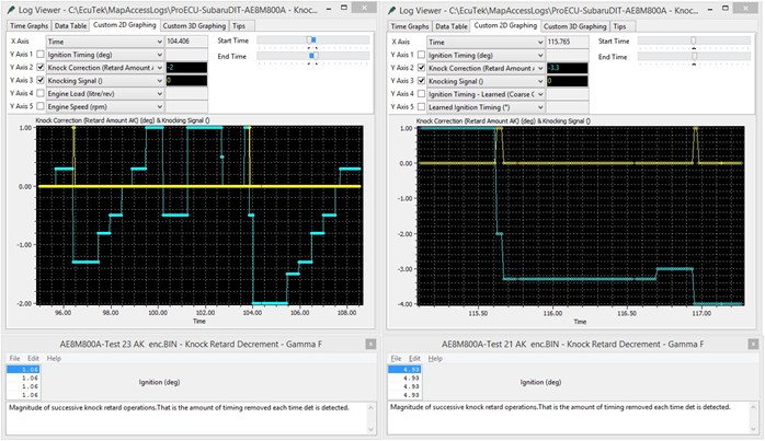
The left hand side shows the small amount of retard applied when the knocking signal becomes active, with AK showing -1deg. The right hand side shows a much larger retard amount is applied when the knocking signal becomes active with AK showing -3.3deg. You can also see that for subsequent knock signal events that AK will reduce further. This is a severe test but it has been to show the knock control in more detail. Raising the value in the map called Fine Ignition Learning Max Advance will allow the ECU to add more than 1deg of advance.
In the above example the Max Advance value has been increased from 1.05deg to 3.85deg and Knock Correction AK (Cyan line) is adding +3.5deg whilst the AM is climbing (Purple line). This Ignition fine learning feedback control is shown in Live Data as the logging parameter called Knock Correction (Retard Amount AK), this control can advance and retard the timing. The maximum amount of advance or retard and the ignition timing step amount used can be adjusted in the Fine Learning maps below.
Knock Retard Maximum
This is the maximum amount of knock regard (AK) the ECU is allowed to remove. The default value is 12 deg, you should not need to increase this value.
Knock Retard Decrement – Gamma F
This is the magnitude of successive knock retard operations. So the amount of timing removed each time knock is detected, making these values bigger will make the knock retard (AK) amount greater for a given knock event.
Knock Retard Increment – Alpha F
This is the step amount value for reducing the knock retard amount after the knocking has stopped. Making these values bigger will mean the knock retard amount will be phased out more quickly after the knocking event has finished.
Knock Retard Increment Delay Period
The time period required to expire when the knock event has finished and the Knock Correction AK can start to be reduced.
Knock Sensitivity
The Knock Sensitivity Per Cylinder maps show the knock sensor threshold where knock correction will become active for each cylinder. If the threshold is breached (for a given RPM and Load) then the knock correction parameter will start to show knock retard and will therefore be retarding the Ignition Timing to reduce cylinder pressure and avoid subsequent knock events.
Increasing these values will result in reduced Knock Correction amount (less retard) for a given knock sensor noise level, so an overall reduction in knock sensitivity. This will allow more Ignition Advance before knock is detected though extreme care must be taken to ensure true knock is still detected!
Reducing these values will result in an increased Knock Correction amount (more retard) for a given knock sensor noise level, so an overall increase in knock sensitivity. This will allow less Ignition Advance before knock is detected.
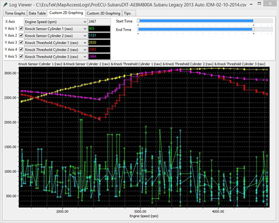
You will see from the log file below that some cylinders have different thresholds to others and that Cylinder 2 has a low threshold compared to Cylinders 1 or 3.
The logging rate cannot capture all knock events so use with caution and understanding!
Ignition Fine Learning Control
When the Advance Multiplier is less than 1 then the ECU will adopt a fine learning control to constantly correct and optimise the Ignition Timing to the point of knock. When no knock is present the ECU will raise the Advance Multiplier.
This Ignition fine learning feedback control is shown in Live Data as the logging parameter called Knock Correction (Retard Amount AK), this control can advance and retard the timing. The maximum amount of advance or retard and the ignition timing step amount used can be adjusted in the Fine Learning maps below.
If Knocking Correction shows a -4 deg has been removed from the current Ignition timing calculation then 50% of this Knock Correction amount (-2 deg) will be stored in memory for a given RPM and Engine Load range for next time. If a negative value is already stored for that RPM and Load then the value is simply added to stored ‘Fine Learning value’ If -1 deg was already stored in memory for a given RPM and Load then a further -2deg would also be added making a total of -3 deg stored for the same RPM/Load memory location. The next time the engine passes the same RPM and Engine Load then the Fine Learning value (3 deg) would be recalled and subtracted from the Ignition Timing calculation at that point. This is the principle of the Fine Learning control that is used to adjust the Advance Multiplier.
When the learned value is 50% or greater than the corresponding values in the Ignition Advance map then the AM will be decreased and all Fine Learning stored values are cleared and the process starts all over again. In the event that no further knocking is experienced then the ECU will add positive Fine Learning values in +0.35 deg increments to build out the learned negative values. When all negative values have been built out and the positive values are 50% or greater than the values in the Ignition Advance map then the AM will increase and therefore advance the whole ignition curve.
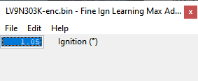
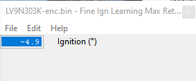
Fine Ign Learning Max Advance
The maximum advance value that is allowed when fine learning is active, this will be shown in the logging parameter Knock Correction (Retard Amount AK). Raising this value will allow the feedback control to add more advance, the default value is 1.05deg and the ECU will not add more than 1.05deg in the event of no knock whilst waiting for the Advance Multiplier to increase.
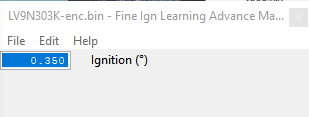
Fine Ign Learning Advance Magnitude
This is the step size of the Fine Learning when advancing the Ignition Timing. The default value is 0.35deg.
Fine Ign Learning Max Retard
The maximum retard value that is allowed when fine learning is active, this will be shown in the logging parameter Knock Correction (Retard Amount AK).
Increasing this value will allow the feedback control to remove more Ignition (retarding the timing further), the default value is -4.9deg and the ECU will not retard the Ignition more than this in the event of continuous engine knocking. Some tuners reduce this value to prevent the ECU from removing too much timing.
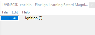
Fine Ign Learning Retard Magnitude #1/ #2
This is the amount of retard applied in the event of feedback control knock. The default value is 1.40deg so the Ignition will be retarded in 1.40deg steps whilst knocking is occurring. Increasing this value from 1.4 to 4.0deg will mean the fine learning will be more aggressive when it removes ignition timing.
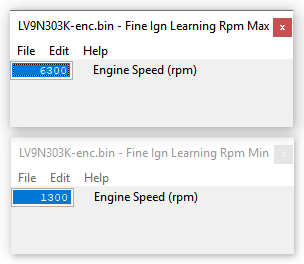
Fine Ign Learning Rpm Min/Max
The minimum and maximum Engine Speed (RPM) for the ECU to store the Fine Ignition Learning.
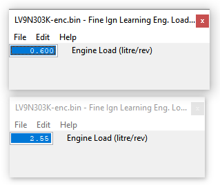
Fine Ign Learning Eng. Load Min/Max
The minimum and maximum Engine Load for the ECU to store the Fine Ignition Learning.
Limiters
Speed Limiter
This controls the maximum vehicle speed by reducing the accelerator pedal % when approaching high speeds. It is suggested that the vehicle speed values are all increased by the same amount in all the speed limit maps and that the accel/throttle control is not adjusted.
Speed Limiter minimum RPM
The minimum engine speed for the Speed Limiter to be enabled.
Rev Limit A and B
This controls the engine speed that the fuel injectors will be cut to maintain a set RPM. If the Rev Limit is to be increased by 300rpm then add 300 to all Rev Limit values in Map A and B.
Fuel Cut Resume
When Fuel Cut (Rev Limit) is active the Manifold Pressure must drop below this threshold before the Fuel Injection will be restored (Rev Limit off).
Cruise Speed Limit Min and Max
These are the minimum and maximum vehicle speed limits (km/h) at which the cruise control can be set. Check the Help Text for each map to understand its exact function.
Load
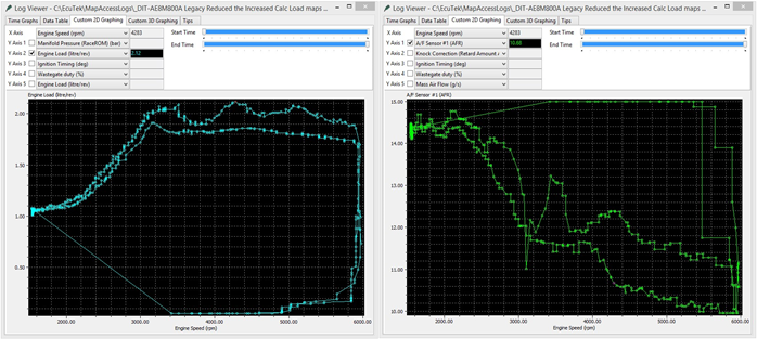
Engine Load compensation
These 3d maps are used a part of a volumetric efficiency calculation to correct the engine load in certain conditions. Increasing or decreasing the map values will directly affect Engine Load, Ignition Timing and Injector open time but it does not affect the Mass airflow (as shown in the mass airflow logging parameter).
You can see below the effect on Engine Load and therefore Ignition Timing and AFR, the left hand log shows how the engine load increases when the VE map is increased by 30%, the right hand log shows the change in AFR on full load (in open loop).
Map List
Live Data Parameters
- Engine Speed RPM
- Engine Load
- TGV Status
Sensor Scaling
MAP Sensor Scaling – Pressure Offset
Manifold Absolute Pressure sensor offset in bar.
MAP Sensor Scaling – Voltage Multiplier
Manifold Absolute Pressure sensor multiplier in bar per volt.
MAF Sensor Scaling
This map can be used to rescale the Mass Air Flow sensor relation between voltage and Mass Air Flow in g/s. Change this value if you have changed the MAF housing or intake system of if your AFR does not match what’s in your fuel map.
Air Intake Temperature Sensor Scaling
This map can be used to rescale the intake air temperature sensor voltage to temperature scaling.
Charge Air Intake Temperature Sensor Scaling
This map can be used to rescale the charge air temperature sensor voltage to temperature scaling.
Coolant Temperature Sensor Scaling
This map can be used to rescale the coolant temperature sensor voltage to temperature scaling.
Oil Temperature Sensor Scaling
This map can be used to rescale the oil temperature sensor voltage to temperature scaling.
AF Sensor Scaling
This map converts the AF Sensor current draw (in milliamp) to an AFR value, there should not be any reason to change these maps.
Map List
Live Data Parameters
- Coolant Temperature
- Oil Temperature
- Intake Air Temperature
- Charge Air temperature
- Mass Air Flow
- Mass Air Flow Sensor
- Manifold Absolute Pressure
Misc.
EGR Control
EGR TGV Closed
This shows the target EGR amount whilst the Throttle Generator Valves (TGV) are closed. This would be used at light load and low RPM.
EGR TGV Open
This shows the target EGR amount whilst the Throttle Generator Valves (TGV) are open. This would be used at medium to full load.
EGR – Temperature Compensation
The coolant temperature compensation for EGR control maps. Setting this map to 0% will disable the EGR maps.
Map List
Live Data Parameters
- TGV Drive
- TGV Output
- TGV Position
- EGR Error
- EGR No. Steps
EcuTek ProECU tuning tools tools should only be used by experienced tuners who understand the product and engine calibration.
If you do not fully understand this product then you WILL damage your engine, ECU or your vehicle.
Please ensure you fully read all EcuTek manuals BEFORE attempting to use ProECU with your laptop or your vehicle.
Use with extreme caution and understanding at all times, if in doubt then do not proceed.
EcuTek accepts no responsibility for any damage to the engine, ECU or any part of the vehicle that results directly or indirectly from using the product.
** If you are in any doubt that you do NOT have the experienced required to use this product then you should NOT USE IT **
Retail customers
** If you have any doubt that you do NOT have the experienced required to use this product then you should NOT USE IT, you should simply contact your EcuTek Master Tuner shown clearly on the top of your Programming Kit or visit your preferred tuning shop to have a professional tuner to use it for you **