Subaru DIT RaceROM Guide
- Brandyn Mowat
- Chris Todd
![]()
RR Tuning Guide
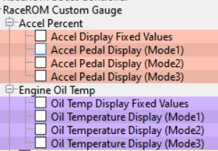
Custom Gauge
Custom Gauge allows the tuner to display either a fixed value, or the output of a custom map, on the dashboard gauges. The exact functionality depends on the type of gauge cluster fitted to the vehicle.
It can be used, for example, to display the required fuel octane for each map switch mode, to display current AFR, or the output of an external fuel ethanol content sensor.
The custom gauge feature allows custom values to be displayed on the dashboard gauges. The functionality differs depending on which gauges are fitted to the vehicle.
In the example shown here, the Accel % gauge has been configured to show the fixed values 1, 2 and 3 during map switching when the vehicle is stationary.
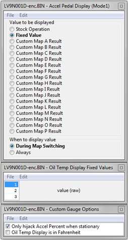
When tuning vehicles with automatic transmissions you should only hijack the Accel gauge when the vehicle is stationary, because the Transmission Control module may use the displayed value as part of its gear selection decision.
Note that some gauges have a limited range and may not be able to display the desired value. This is a feature of the gauge and is not something we are able to control.
The Oil Temp gauge cannot display below 100F and any value below this will be shown as dashes (---).
Maps
Launch Control with Boost Off The Line
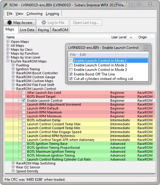
The Launch Control feature limits maximum RPM during launch in an attempt to control wheel spin and allow the fastest possible take off. The driver can adjust the launch RPM using the cruise control buttons.
In addition, you can specify a pre-launch manifold pressure target for each map switch mode. The ECU will dynamically retard and advance the ignition timing in order to achieve the target.
When Launch Control is active, the rev limit will be set to the ‘Launch RPM’. This limit defaults to the 'Launch Control RPM Default" value and can be adjusted up and down using the cruise control stalk. Select "Res/Acc" to increase the launch RPM and "Set/Cst" to decrease it.
During the launch, the rev limit increases according to the 'After Launch Rev Limit’ map , This 2D map, indexed by elapsed time, is added to the Launch RPM and has multiple columns to allow you to set up a multi-stage system for best results.
An adjustment is provided that allows you to control the target AFR when the vehicle is stationary if necessary. This adjustment is removed as soon as the vehicle starts to move.
The ECU will choose a boost target according to the BOTL boost target values. There is one for each map switch mode. It will then set the ignition timing according to the BOTL ignition timing base map. Then it adjusts the ignition timing in a closed loop manner according to the BOTL Ignition Timing Proportional map which is driven by boost error. If the boost is too low, timing will be retarded to increase the anti-lag effect, if the boost is too high, timing will be advanced to reduce the effect.
Rolling Fuel Cut
By default, the ECU will cut the fuel to all four cylinders in order to maintain the launch RPM. An alternative method can be employed which cuts individual cylinders in rolling pattern, which may be preferred in some cases. This can be activated by un-checking the box in the “Enable Launch Control” map.
How to Use RaceROM Launch Control
- Ensure the ‘Launch Control Enable’ checkbox is ON for the current Map Switch Mode
- Engine must be running and Vehicle must be stationary
- Engine coolant temperature must be within the allowed range
- Press clutch pedal and move the gear stick to 1st position
- Quickly press the accelerator all the way to the floor
- Adjust launch RPM using the cruise control stalk
- Release the clutch to commence launch
The Launch Control feature is deactivated when one of the following conditions occurs:
- The vehicle speed exceeds the last column on the ‘After Launch Rev Limit’ Map.
- The driver lifts off the accelerator
- The driver performs a flatfoot shift
Map Switching
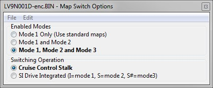
The Map Switching feature allows you to define three different calibrations in the ECU ROM. The driver can switch between the calibrations using the cruise control lever. Alternatively the map switching can be seamlessly integrated with the SI drive system.
The Map Switching feature can also be used as a trigger to activate other RaceROM features. For example: the Launch Control and Flat Foot Shift features can each be configured to operate in any of the three modes.
The Map Switching feature is enabled by the option buttons in the ‘Map Switch Options' map. Three modes are allowed by default, but this can be reduced if desired.
In “Mode 1”, the ECU will use the original ECU maps for Fuelling, Injector Flow, Base Ignition Timing and Ignition Advance.
In the other three modes, the ECU will use the new Fuel, Injector Flow and Ignition Timing maps labelled Mode2 and Mode3 as appropriate.
For more information on how to use the system, check out our article RaceRom Map Switching
Integration with Launch Control and Flat Foot Shifting*
The Launch Control and Flat Foot Shifting* features can be independently enabled in each of the three modes.
Logging
The “Mapswitch Mode” diagnostic parameter can be used to log the current map switch mode.
EcuTek ProECU tuning tools tools should only be used by experienced tuners who understand the product and engine calibration.
If you do not fully understand this product then you WILL damage your engine, ECU or your vehicle.
Please ensure you fully read all EcuTek manuals BEFORE attempting to use ProECU with your laptop or your vehicle.
Use with extreme caution and understanding at all times, if in doubt then do not proceed.
EcuTek accepts no responsibility for any damage to the engine, ECU or any part of the vehicle that results directly or indirectly from using the product.
** If you are in any doubt that you do NOT have the experience required to use this product then you should NOT USE IT **
Retail customers
** If you have any doubt that you do NOT have the experience required to use this product then you should NOT USE IT, you should simply contact your EcuTek Master Tuner shown clearly on the top of your Programming Kit or visit your preferred tuning shop to have a professional tuner use it for you **