Subaru EJ RaceROM Supplement
- Brandyn Mowat
- Lucan Hetherington
- Phil Baucutt
![]()
Subaru EJ ProECU Tuning Guide: RaceROM Supplement
Map Switching
The Map Switching feature allows you to define two different calibrations in the ECU ROM. The driver can switch between the calibrations at the press of a button. It is envisaged that this feature will be used to provide an economical calibration for everyday road use and a maximum performance calibration for use at the track. For this reason, we refer to the two calibrations as “Road Mode” and “Race Mode”. Alternatively you could use this feature to provide two calibrations optimised for different grades of fuel. Or you could provide a low performance “Valet Mode”, an “Emissions Test” mode, or even an “Anti-Theft Mode” that doesn’t allow the engine to start.
This feature can be integrated with Subaru’s SI drive system, where fitted, or can provide SI drive type functionality to vehicles that do not have it. It can also be integrated with the "Eco" mode on some vehicles. additionally the Map Switching feature can also be used as a trigger to activate other RaceROM features. For example: the Launch Control, Flat Foot Shift and Autoblip features can each be configured to operate in either "Road" mode, "Race" mode, or both.
Operation
The Map Switching feature is enabled by the checkboxes in the ‘MS enable’ map. When this feature is operational, the ECU can be programmed with two different calibrations and the driver can switch between them. We refer to these calibrations as “Road” mode and “Race” mode.
In “Road” mode, the ECU will use the original ECU maps for Fuelling, Ignition Timing, Boost, Wastegate, VVT, Accelerator Response and Rev Limit. In “Race” mode the ECU will use the new maps described below. We have tried to ensure that the ECU will remain in the chosen mode when the ignition is turned off. This is not always possible and some older vehicles will default back to "Road" mode when the ignition is turned off. The Map Switching Feature will default back to “Road” mode if the vehicle battery is disconnected, or an ECU reset is performed.
Switching between Map Slots
Without SI Drive
The driver can toggle between “Road” and “Race” modes by turning on the rear window demist switch while holding the accelerator to the floor.
The check engine light will flash to indicate which mode has been set:
- One Long Flash means that the vehicle is now in “Road” mode.
- Eight Short Flashes means that the vehicle is now in “Race” mode.
Integration with Subaru SI Drive
For vehicles fitted with Subaru’s SI Drive system, the “Race Mode” can be automatically activated when the driver sets the SI control to the “Sport #” position. This feature is enabled by the ‘Engage race mode in Sport# SI mode’ checkbox. In this situation, the Check Engine light does not flash to indicate the current Map Switch mode. For simplicity, we suggest that on cars fitted with SI drive, you use ‘Engage race mode in Sport# SI mode’ in preference to ‘Switch mode on full throttle + defog switch’ and do not enable them both at the same time. When the ECU is in ‘Race’ mode, it will always use the ‘Accel Pedal to Desired Torque Sport#’ map for calculating accelerator response, even if the SI knob is in a different mode and you have engaged the Race mode using the “full-throttle + defog” method. Do not enable the ‘Engage race mode in Sport# SI mode’ checkbox on vehicles without an SI Drive knob.
Integration with Eco Switch
For vehicles fitted with an ECO switch, the “Race Mode” can be made to activate when the driver turns the ECO switch off. This feature is enabled by the ‘Engage Race Mode when ECO switch is off’ checkbox. In this situation, the Check Engine light does not flash to indicate the current Map Switch mode. The “Race Mode” does not get engaged when the ECO light automatically switches off due to uneconomical driving style. Race Mode will only be engaged if the driver turns off the ECO switch. Do not enable the ‘Engage Race Mode when ECO switch is off’ checkbox on vehicles without an ECO switch.
Integration with Per Gear Boost Control Feature
Per Gear Boost Control can be enabled in either “Road”, “Race”, or both modes. When the Per Gear Boost Control feature is enabled, the original ECU boost and wastegate maps are only used when the gearstick is in Neutral. Each Map Switch mode has its own separate set of per-gear boost and wastegate maps. When Per Gear Boost Control is NOT enabled, “Road” mode will use the original ECU boost and wastegate maps. “Race” mode will use the “PGB Race Mode 1st” boost and wastegate maps in ALL gears.
Integration with Launch Control, Flat Foot Shifting and Auto Blip
The Launch Control, Flat Foot Shifting and Auto Blip features can be independently enabled in either “Road”, “Race” or both modes.
Logging
The “SI Drive Mode” diagnostic parameter can be used to log the current map switch mode. On vehicles that do not have SI Drive, the data logger will report “Intelligent” if the vehicle is in “Road” mode or “Sport” if the vehicle is in “Race” mode.
Related Maps
- Special Features\Enable Road/Race Map Switching - This map holds the checkboxes that enable the Map Switching feature.
- Fuelling\Lo Det Fuel Map Race - This map is used in “Race” mode instead of the original ECU “Lo Det Fuel” map.
- Fuelling\Hi Det Fuel Map Race - This map is used in “Race” mode instead of the original ECU “Hi Det Fuel” map.
- Fuelling\Fuel Base Map Race - This map is used in "Race" mode instead of the original ECU "Fuel Base" map on vehicles that use the Base+Enrichment fuelling strategy.
- Fuelling\Fuel Enrichment Race - This map is used in "Race" mode instead of the original ECU "Fuel Enrichment" map on vehicles that use the Base+Enrichment fuelling strategy.
- Ignition Timing\Ignition Base Map Race - This map is used in “Race” mode instead of the original ECU “Ignition Base” map.
- Ignition Timing\Ignition Advance Race - This map is used in “Race” mode instead of the original ECU “Ignition Advance” map.
- Cam Timing\Intake\Intake Cam Adv. Race - This map is used in “Race” mode instead of the original ECU “Intake Cam Advance” map.
- Cam Timing\Exhaust\Exhaust Cam Adv. - Race This map is used in “Race” mode instead of the original ECU “Exhaust Cam Adv” map.
- Torque Calculations\Accelerator to Torque\Accel Pedal to Desired Torque - Race This map is used in “Race” mode instead of the original ECU “Accel Pedal to Desired Torque” map(s).
- Fuelling\Closed Loop\Closed Loop AFR Race - This map is used in “Race” mode instead of the original ECU “Closed Loop AFR” map(s).
- Limiters\Per Gear Rev Limits\Per Gear Rev Limits race - This map is used to define the rev limits for each gear in race mode. If Per Gear Rev Limits is not enabled, then the 1st gear limit will be used.
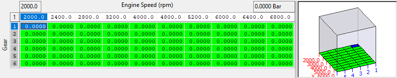
- Boost Control\Desired Boost\Per Gear\Road\Desired Boost Road 1st - This map is used in “Race” mode instead of the original ECU “Desired Boost” map. If the “Per Gear Boost Control” feature is enabled
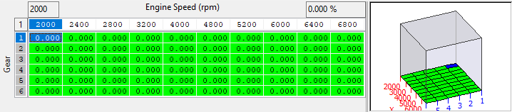
then the additional maps for 2nd through 6th gears will also be used. - Boost Control\Wastegate Duty\Per Gear\Road\WG Duty Initial Road 1st - This map is used in “Race” mode instead of the original ECU “Initial Wastegate Duty” map. If the “Per Gear Boost Control” feature is enabled then the additional maps for 2nd through 6th gears will also be used.
- Boost Control\Wastegate Duty\Per Gear\Road\WG Duty Max Road 1st - This map is used in “Race” mode instead of the original ECU “Max Wastegate Duty” map. If the “Per Gear Boost Control” feature is enabled then the additional maps for 2nd through 6th gears will also be used.
- Limiters\Vehicle Speed\Veh. Speed based Throttle Angle Limiter Race - This map is used in "Race" mode instead of the original ECU "Veh. Speed based Throttle Angle Limiter".
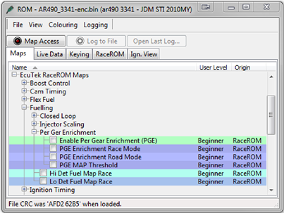
- Fuelling\Per Ger Enrichment\PGE Enrichment Race Mode - This map is used in "Race" mode to enrich the fuelling on a per gear basis.
Per Gear Boost Control
The Per Gear Boost Control feature allows you to define a separate boost calibration for each gear. This can be used to provide a higher boost level in lower gears for rapid acceleration while maintaining the standard boost level for cruising in the higher gears.
Method of Operation
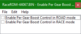
The Per Gear Boost Control feature is enabled by the ‘Enable Per Gear Boost Control’ checkboxes in the ‘PGB enable’ map. When this feature is enabled, the ECU will use separate Boost and Wastegate maps for each gear.
Gear Determination
The ECU determines which gear it is in by dividing vehicle speed by rpm and matching the result against the ‘Gear Thresholds’ map. The units of this map are in km/h per 1000 rpm. Experience has shown that the default values in this map do not always identify the gear correctly. For best results, we recommend that you log the “Vehicle Speed”, “RPM” and “Gear Position” parameters and modify this map appropriately.
On vehicles fitted with Automatic Transmissions, gear determination may be unpredictable when the Torque Converter is unlocked.
Integration with Map Switching Feature
Separate set of Boost and Wastegate offset maps are provided for the “Road” and “Race” modes.
Integration with Eco Switch
When Per Gear Boost Control is enabled, the PGB boost maps are used in preference to the ECO boost maps. If you wish to retain the Eco functionality, we recommend using the Map Switch feature to “engage Race mode when the Eco switch is OFF”, and then only enable Per Gear Boost in Race mode. This will enable the Eco boost maps when the Eco switch is on, and the Per Gear Boost maps when the Eco switch is off.
Alternative Implementation
A small number of older ECUs (eg. USA 2004 STi AJ240) are not compatible with our standard Per Gear Boost system described above. For these vehicles, we have developed an alternative system that uses the original tables for “Road” mode and a separate set for “Race” mode. A per-gear compensation factor can then be applied to these tables in order to achieve per-gear boost control.
- Boost Control\Desired Boost\Per Gear\Desired Boost per gear compensation - This map is used by the alternative implementation of PGB. It specifies a per-gear compensation factor to be applied to the base Desired Boost map.
- Boost Control\Wastegate Duty\Per Gear\WG Duty Initial per gear compensation - This map is used by the alternative implementation of PGB. It specifies a per-gear compensation factor to be applied to the base Initial Wastegate Duty map.
Related Maps
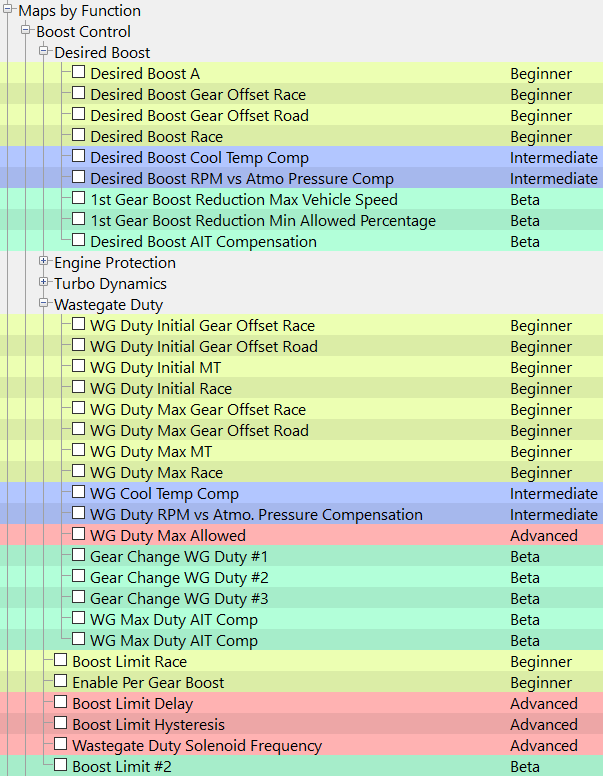
- Boost Control\Per Gear\Enable Per Gear Boost - This map holds the checkbox that enables the Per Gear Boost Control Feature.
- Boost Control\Desired Boost\Per Gear\Race\Desired Boost Offset Race 1st - This map is used to offset the original Desired Boost map when the vehicle is in each Gear and the Map Switch feature is in ‘Race’ mode. Similar maps are provided for both ‘Road’ and ‘Race’ modes. There are 2 “PGB Desired Boost” maps in total.
- Boost Control\Wastegate Duty\Per Gear\Race\WG Duty Initial Offset Race 1st - This map is used yo offset the original Initial Wastegate Duty map when the vehicle is in each Gear and the Map Switch feature is in “Race” mode. Similar maps are provided for both ‘Road’ and ‘Race’ modes. There are 2 “PGB Initial Wastegate Duty” maps in total.

- Boost Control\Wastegate Duty\Per Gear\Race\WG Duty Max Offset Race 1st - This map is used to offset the original Max Wastegate Duty map when the vehicle is in each Gear and the Map Switch feature is in “Race” mode. Similar maps are provided for both ‘Road’ and ‘Race’ modes. There are 2 “PGB Max Wastegate Duty” maps in total.
- Boost Control\Wastegate Duty\Per Gear\WG Duty Max per gear compensation - This map is used by the alternative implementation of PGB. It specifies a per-gear compensation factor to be applied to the base Max Wastegate Duty map.
Per Gear Fuel Enrichment
The Per Gear Enrichment feature allows you to run leaner AFR in lower gears during rapid acceleration and a richer AFR in higher gears for prolonged driving at higher speed.
Method of Operation
The Per Gear Fuel Enrichment feature is enabled by the Fuelling\Per Ger Enrichment\Enable Per Gear Enrichment’ checkbox. When this feature is enabled, the ECU will apply a fuelling adjustment based on gear position and RPM. The enrichment is only applied when MAP exceeds a preset threshold.
Gear Determination
The ECU determines which gear it is in by dividing vehicle speed by rpm and matching the result against the ‘Gear Thresholds’ map. The units of this map are in km/h per 1000 rpm. Experience has shown that the default values in this map do not always identify the gear correctly. For best results, we recommend that you log the “Vehicle Speed”, “RPM” and “Gear Position” parameters and modify this map appropriately. On vehicles fitted with Automatic Transmissions, gear determination may be unpredictable when the Torque Converter is unlocked.
Integration with Map Switching Feature
Separate sets of Per Gear Rev Enrichment maps are provided for the “Road” and “Race” modes.
Related Maps
- Fuelling\Per Gear Enrichment\Enable Per Gear Enrichment - This map holds the checkbox that enables the Per Gear Enrichment feature.
- Fuelling\Per Gear Enrichment\PGE Enrichment Road Mode - This map holds the enrichments for each gear in “Road” mode.
- Fuelling\Per Gear Enrichment\PGE Enrichment Race Mode - This map holds the enrichments for each gear in “Race” mode.
- Fuelling\Per Gear Enrichment\PGE MAP Threshold - The per gear enrichment is applied when MAP exceed this threshold.
Per Gear Rev Limits
The Per Gear Rev Limits feature allows you to define different rev limits for each gear. By setting a higher rev limit in lower gears you may be able to reduce the number of gearshifts required in attaining a given speed. Eg. 0-60mph or 0-100km/h tests.
Per Gear Rev Limits Feature
Method of Operation
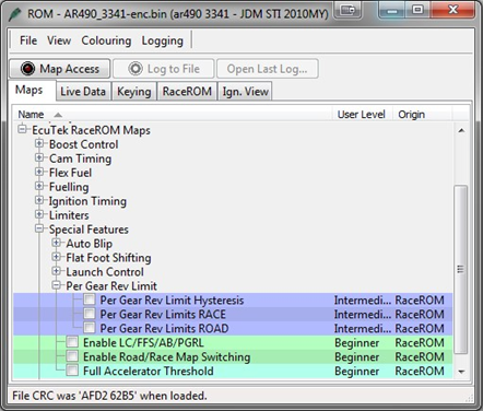
The Per Gear Rev Limits feature is enabled by the ‘Enable Per Gear Rev Limit’ checkboxes in the ‘enable LC/FFS/AB/PGRL map. When this feature is enabled, the ECU will use separate rev limits for each gear. The upper rev limit (fuel cut) is defined in the “Per Gear Rev Limits Road” map in “Road” mode and “Per Gear Rev Limits Race” map in “Race” mode. The top value is for 1st gear, the next is for 2nd gear, etc. The bottom value is for 6th gear. The lower rev limit (fuel resume) is calculated by subtracting the value of “Per Gear Rev Limit Hysteresis” from the upper limit. For example, if the upper limit for the current gear is 7000 and the hysteresis is 100 then the lower limit will be 6900.
Gear Determination
The ECU determines which gear it is in by dividing vehicle speed by rpm and matching the result against the ‘Gear Thresholds’ map. The units of this map are in km/h per 1000 rpm. Experience has shown that the default values in this map do not always identify the gear correctly. For best results, we recommend that you log the “Vehicle Speed”, “RPM” and “Gear Position” parameters and modify this map appropriately. On vehicles fitted with Automatic Transmissions, gear determination may be unpredictable when the Torque Converter is unlocked.
Integration with Map Switching Feature
Separate sets of Per Gear Rev Limit maps are provided for the “Road” and “Race” modes. When Per Gear Rev Limits are not enabled, “Road” mode will use the original ECU rev limit, “Race” mode will the 1st gear value of the “Per Gear Rev Limit Race” map in all gears.
Speed Density
The Speed Density feature changes the way that mass airflow is calculated. When SD mode is activated, the ECU will disregard the MAF sensor reading and calculate mass airflow based on Engine Speed, Manifold Pressure and Air Temperature instead. This allows you to remove the MAF sensor and fit a larger intake if desired.
Speed Density Feature
Method of Operation
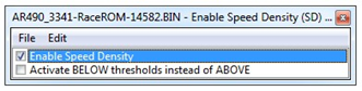
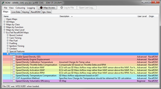
The Speed Density feature is enabled by selecting the checkbox in the Speed Density Enable map.
When this feature is active, the ECU will ignore the reading from the Mass Airflow sensor and will calculate mass airflow as follows:
- Estimated mass airflow is calculated from RPM, Manifold Pressure, Charge Air Temperature, and VE (read from the Speed Density Volumetric Efficiency map) This value is then multiplied by an adjustment factor selected from the 2D “Speed Density Temperature Compensation” map based on Intake Air Temperature.
- This is then multiplied by a value selected from the 2D "Speed Density Throttle Delta Compensation" map, resulting in a mass airflow value in grams/second.
Removal of MAF sensor (optional)
It is expected that this feature will be used in applications where you wish to replace the MAF sensor with a custom intake. If you remove the MAF sensor, you must go to the “Enabled Diagnostic Trouble Codes” map and disable the codes relating to MAF sensor errors. If you do not disable these codes then the ECU will detect a “Mass Airflow sensor failure” and use its fallback processing instead of the Speed Density feature. The Subaru intake air temperature sensor is built into the MAF sensor. If you remove the MAF sensor itself, then you must fit a replacement intake air temperature sensor. If an aftermarket air temp sensor is fitted, then be sure to rescale the “Air Intake Temperature Sensor Scaling” map. This sensor can be fitted in the intake manifold measuring charge air temperature, rather than intake air temperature if required. Remember to change any intake air temperature compensation maps if you switch to charge air based temperature compensation.
Using Speed Density and MAF sensor together
The Speed Density feature can also be useful in applications where the MAF sensor is present, but the amount of airflow is higher than the MAF sensor can measure. In this scenario, the ECU can be programmed to use the MAF sensor at lower mass airflow values and switch to Speed Density for the higher values.
Speed Density Blend
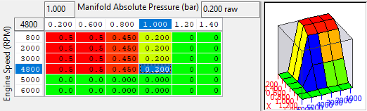
This map is a weighting factor for the MAF derived load vs SD derived load.
The final load is the composite of MAF/SD thus:
ChargeFinal = (ChargeSD * Blend) + (ChargeMAF * (1- Blend))
In simple terms the larger the output of this map the more MAF is used, values of 0 will result in only MAF being considered, values of 1 will result in only SD being considered.
When tuning SD one can start using a MAF blend map filled with 1 and check the MAF scaling, once properly scaled or if using OEM induction it's reasonable to decrease the MAF weighting and begin to tune the SD VE map (remember to set the SD blend map to 1.0 so you're running on RaceROM SD and not the OEM SD).
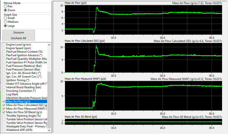
The MAF blend can be monitored in Live Data using the parameter "Mass Air Flow SD Blend", the log image below shows the blend in action.
The Old Method
You can specify threshold values of MAF, RPM and MAP that are required for Speed Density activation. The ECU will activate the Speed Density feature only when all three of these values are above their respective thresholds. The threshold values are implemented using hysteresis. The 1st value should be higher than the 2nd value. The feature will activate when the parameter rises above the 1st value, and will deactivate when it falls below the 2nd value. You can also use the Speed Density feature in applications where the amount of airflow is lower than the MAF sensor can accurately measure. In this situation, enable the “Activate BELOW thresholds instead of ABOVE” checkbox. The ECU will activate the Speed Density feature when MAF, RPM and MAP are all below their respective thresholds. The default value for the thresholds is zero. If you use the “Activate BELOW thresholds instead of ABOVE” checkbox, then the feature will only be activated when all three parameters are below their respective thresholds. Therefore you need to set a high value into any thresholds that you are not using, otherwise the feature will not activate.
Launch Control
The Launch Control feature limits maximum RPM during launch in an attempt to control wheel spin and allow the fastest possible take off.
Method of Operation
Activate the launch control as follows
- Ensure the ‘Launch Control Enable’ checkbox is ON for the current Map Switch Mode
- Engine must be running and Vehicle must be stationary
- Press clutch pedal and move the gear stick to 1st gear position
- Quickly press the accelerator all the way to the floor
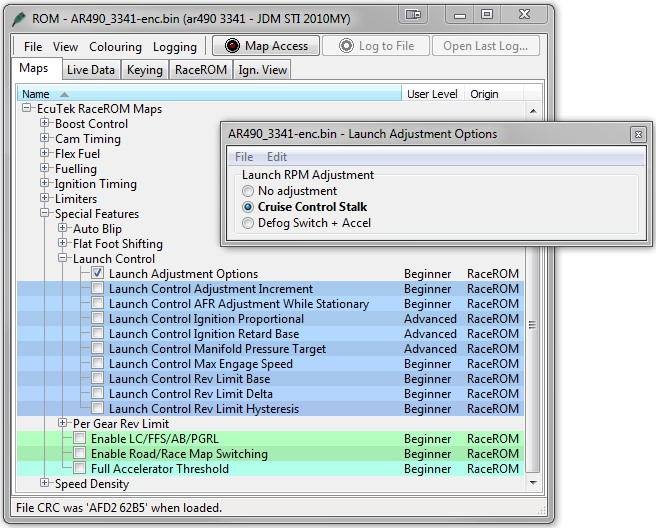
- Adjust launch RPM using the cruise control stalk
- Release the clutch to commence launch
When Launch Control is active (clutch pedal depressed), the rev limit will be set to the ‘Launch Control Rev Limit’. This limit defaults to the 'Launch Control Rev Limit Base" value and can be adjusted up and down using the cruise control stalk. Select "Res/Acc" to increase the launch RPM and "Set/Cst" to decrease it. An alternative method of adjustment is available for vehicles without cruise control. When the clutch pedal is released, the rev limit “restores” according to the 'Launch Control Rev Limit Delta, This 2D map, indexed by elapsed time, has multiple columns to allow you to set up a multi-stage system for best results. Adjustments are provided that allow you to lower the AFR and retard the timing when the vehicle is stationary in order to create pops and bangs. This adjustment is removed as soon as the vehicle starts to move
The Launch Control feature is deactivated when one of the following conditions occurs:
- The elapsed time exceeds the last column on the ‘Launch Control Rev Limit Delta Map’
- The driver lifts off the accelerator
- The driver performs a flatfoot shift
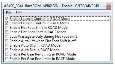
RaceROM Launch Control can be enabled in ROAD mode, RACE mode, or both. Select the appropriate checkboxes in the Enable LC/FFS/AB/PGRL map
Vehicles without cruise control
Set the launch control rev limit as follows:
- Ensure the ‘Launch Control Enable’ checkbox is ON for the current Map Switch Mode
- Engine must be running and Vehicle must be stationary
- Turn on rear window demist switch
- Press clutch
- Increase engine speed and hold at desired launch RPM
- Turn off rear window demist/defogger switch
- The check engine light will flash to indicate that new limit has been saved.
Vehicles with automatic transmission
Activate the launch control as follows
- Ensure the ‘Launch Control Enable’ checkbox is ON for the current Map Switch Mode
- Engine must be running and Vehicle must be stationary
- Press brake pedal and move the gear stick to a “forward drive” position
- Quickly press the accelerator all the way to the floor
- Adjust launch RPM using the cruise control stalk
- Release the brake to commence launch
Ensure that the launch RPM is below the stall speed of the torque converter.
Boost Off The Line (BOTL)
RaceROM allows you to specify a pre-launch manifold pressure target for each mapswitch mode. The ECU will dynamically retard and advance the ignition timing in order to achieve the target.
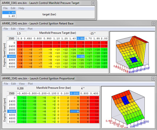
Launch Control Manifold Pressure Target
This map allows you to specify a target manifold pressure in order to generate “Boost Off The Line”.
Launch Control Ignition Timing Base
This map specifies ignition timing based on Manifold Pressure Target and RPM. Retarding the timing generates more manifold pressure. When calibrated correctly, the ECU should be able to maintain the target pressure prior to launch.
Launch Control Ignition Timing Proportional
This map applies an adjustment to the base ignition timing based on the difference between the target and actual manifold pressure. If the pressure is below target, the map will retard the timing further, if the pressure overshoots the target, the map will advance the timing.
Flat Foot Shifting
The Flat Foot Shifting feature allows the driver to up-shift without lifting his foot from the accelerator pedal. This helps to avoid a drop in boost pressure and corresponding loss of power while shifting gear.
Method of Operation
The Flat Foot Shifting Feature (FFS) is activated when all of the following conditions are met:
- ‘The Flat Foot Shift Enable’ checkbox is ON for the current Map Switch Mode
- The vehicle is travelling faster than the ‘Flat Foot Shift Minimum Speed’
- The accelerator amount is greater than the value in the ‘Full Accelerator Threshold Map’ The driver is pressing the Clutch pedal
At the moment when the Flat Foot Shifting feature activates, a temporary rev limit is set that is slightly higher than the current RPM. The ignition timing is retarded by a specified amount that reduces engine torque while preventing the RPM from rising too rapidly. When the driver completes the gear change, the temporary rev limit and timing adjustment are removed.
The Flat Foot Shifting Feature is cancelled when one of the following conditions occurs:
- The driver releases the Clutch pedal The driver lifts off the accelerator
- The vehicle speed falls below the value in the ‘Flat Foot Shift Minimum Speed Map’
Flat-Foot Shifting is not available on vehicles equipped with an automatic transmission
An AFR adjustment is provided that allows you to richen the mixture during the shift. The richer AFR cannot be measured from the exhaust gas due to the operation of the rev limiter.
Integration with Map Switching Feature
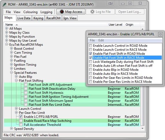
The Flat Foot Shift Feature can be enabled in “Road” or “Race” modes or both by selecting the appropriate checkboxes in the “Enable LC/FFS/AB/PGRL” map.
Safety feature (Auto Lift)
The Auto Lift safety feature can be enabled when Flat Foot Shift is turned off. For example, if FFS is only enabled for "Race" mode then Auto Lift will operate in "Road" mode. If the driver attempts a Flat Foot Shift in the wrong mode then the Auto-Lift feature will momentarily close the throttle in order to soften the shift and prevent mechanical damage. You can enable Auto-Lift by selecting the appropriate checkbox in the "Enable LC/FFS/AB/PGRL" map.
Auto Blip
The Auto Blip feature applies a short burst of throttle when the driver is down-shifting under braking. This raises the RPM to keep the engine operating within its power band and provides a smooth entry into the lower gear by reducing engine braking.
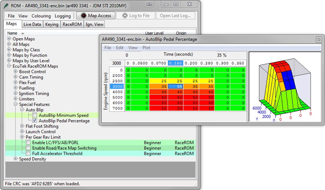
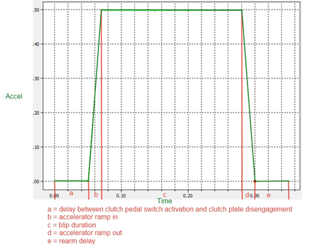
Method of Operation
When the driver down-shifts while braking, the ECU will blip the accelerator. The amount of accelerator to apply and the duration of the blip is controlled by the ‘AutoBlip Pedal Percentage Map’ as shown in the diagram below, this is a 2D slice through the 3D map.
The Auto Blip feature is activated when all of the following conditions are met:
- The ‘Auto Blip Enable checkbox’ is ON for the current Map Switch Mode
- The vehicle is travelling faster than the Auto Blip Minimum Speed
- The driver presses the brake pedal, followed by the clutch pedal
The accelerator blip is immediately cancelled when one of the following conditions occurs:
- The driver releases the Brake Pedal
- The driver releases the Clutch Pedal
- The vehicle speed falls below the ‘Auto Blip Minimum Speed’ The Auto Blip timer reaches the end of the map
Note: Auto Blip is not available on vehicles fitted with Automatic Transmissions.
Integration with Map Switching Feature
The Auto Blip Feature can be enabled in “Road” or “Race” modes or both by selecting the appropriate checkboxes in the “Enable LC/FFS/AB/PGRL” map.
Fail Safes
The Failsafe feature applies a limit to the accel pedal when the one of the monitored changes goes outside of the threshold ranges, the intent is to reduce the load on the engine to a safe operating level and warn the driver that something has gone wrong. This failsafe limit is help for a set time period or until ignition off. There are currently two failsafe channels available using Custom sensor imports, these sensors will need to be configured correctly for failsafes to work correctly. See Subaru CAN Custom Sensors.
Failsafe's that are active are stored into memory (which is reset on key off) and can be seen in the logging parameters

The logged values are (note only 2 options are available for Subaru CAN)
| 1 | Knock Retard |
| 2 | Low Oil Pressure |
| 4 | High Oil Temperature |
| 8 | High Short Term Fuel Trim |
| 16 | Low Relative Fuel Pressure |
| 32 | Lean AFR |
| 64 | High Coolant Pressure |
| 128 | Custom Maps Limp Mode Flag |
Note: These logged values are displayed as a sum e.g. 3 = 1 +2 = Knock Retard & Low Oil Pressure active
Enabling Failsafes
Simply Check the box to enable the failsafe
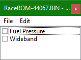
Triggering Failsafes
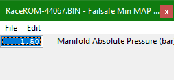
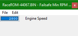
The Failsafe channels are not checked until Manifold Pressure and engine speed thresholds are met to stop false triggering. There are Current two thresholds that must be exceeded before the failsafe function checks the channels and become armed
- Manifold Absolute Pressure (MAP)
- Engine Speed
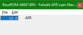
Once the failsafe function is active and its checking the inputs against their thresholds the following maps set the allowable
- Failsafe AFR Leam Max - if the AFR is above the this value and the failsafe is armed the accel pedal limit will be imposed
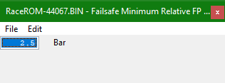
- Failsafe Minimum Relative FP (Fuel Pressure) - If the relative fuel pressure drops below the value the failsafe is triggered
Method of Operation
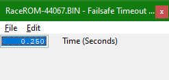
When failsafe are armed and the the trigger thresholds have been met the Failsafe Timeout is started
- Failsafe Timeout - wait time before applying the Failsafe Accel Limit
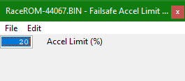
function applies an accel pedal limit to reduce power output for engine safety and to alert the driver that something has gone wrong. The Pedal limit is defined by
- Failsafe Accel Limit - This is a cap to the accel pedal value
- Failsafe Reset Timer - this is the amount of time that the accel pedal limit is held for after this time period 100% accel can be applied

EcuTek ProECU tuning tools tools should only be used by experienced tuners who understand the product and engine calibration.
If you do not fully understand this product then you WILL damage your engine, ECU or your vehicle.
Please ensure you fully read all EcuTek manuals BEFORE attempting to use ProECU with your laptop or your vehicle.
Use with extreme caution and understanding at all times, if in doubt then do not proceed.
EcuTek accepts no responsibility for any damage to the engine, ECU or any part of the vehicle that results directly or indirectly from using the product.
** If you are in any doubt that you do NOT have the experienced required to use this product then you should NOT USE IT **
Retail customers
** If you have any doubt that you do NOT have the experienced required to use this product then you should NOT USE IT, you should simply contact your EcuTek Master Tuner shown clearly on the top of your Programming Kit or visit your preferred tuning shop to have a professional tuner to use it for you **