Subaru EJ Engine ProECU Tuning Guide
- Brandyn Mowat
Subaru EJ Engine ProECU Tuning Guide
WRX, STI, Forester, Legacy (02-12)
Tuning Guide
Always Take a Baseline
Before performing any tuning or hardware modifications, take a baseline log (and dyno run if possible) of the car’s current performance. DeltaDash may be used to log parameters such as ignition timing, knock correction, injector duty, boost pressure, EGT and engine RPM.
Once a baseline reading has been taken, subsequent modifications may be measured against the original.
Before embarking on any modifications to engine or ECU, satisfy yourself that the car has no faults or problem to begin with. Check for diagnostic trouble codes using DeltaDash and ensure any prior modifications are compatible with the work that you have been asked to carry out. E.g. If a customer has requested that a larger turbo be fitted and tuned, but the up-pipe catalytic converter is still present, then it will not be safe to carry out this work.
Tuning for Power
For a given engine configuration, there are a number of tuning techniques that allow more power to be produced.
Increase Air Flow
There are a number of ways to increase the air flow through the engine:
Exhaust Systems
By making the exhaust system less restrictive, air flow may be increased.
Boost Pressure
Increasing the boost pressure that the turbo produces will force more air through the system.
Bigger Turbo
Larger turbo are capable of flowing more air, with less exhaust gas restriction, at the expense of greater lag and lower torque at low revs.
Up-rated Intercoolers
Intercoolers that raise the density of the charge (by reducing temperatures) or decrease the pressure differential across them (by being freer flowing) increase air flow.
Induction Kits
Induction kits that are less restrictive than standard will allow more air to flow. However, many induction kits upset air flow metering and require careful handling.
Advance Ignition Timing
The more ignition advance that can be applied without detonation, the more power will be produced. This is why the ECU runs highly active ignition timing that always attempts to run on the point of detonation.
Most mechanical changes made will have an influence on the amount of advance that can be applied. Extensive use of live map access to monitor ignition timing can yield good results.
The richer the fuel mixture, the more ignition timing can be run. Ignition timing and fuel mixture are interrelated, so be careful when altering one – monitor the other. High RON/MON fuel will also allow more ignition advance.
Optimise Air Fuel Ratios
Maximum power is produced at an AFR of 12.5:1, approximately. Richer mixtures than this provide cylinder cooling and lower EGTs. Leaner mixtures are more economical but raise EGTs and are more susceptible to detonation.
Modification List
Results of changes to mechanical configurations of the engine must be optimised by ECU tuning. In some circumstances, the fitting of high performance parts will reduce engine power until compensated for in the ECU – a very common example of this is induction kits. Fitting of an induction kit with no ECU compensation mapping often results in poor turbo spool up, hesitation, and lean mixtures and in extreme circumstances engine failure. However with the same kit fitted, but with the ECU correctly mapped, will produce worthwhile power improvements with none of the problems detailed above.
In the following sections, a number of common modifications are listed. Under each heading, the parameters that may need attention are described. This data is provided to assist the tuner when ECU tuning to account for hardware modifications.
The ECU changes suggested are to compensate for the mechanical changes. In order to produce further power, the tuner should refer to the standard power tuning rules above.
Under each mechanical modification heading below, the parameters to modify are split into two sections:
The ‘Compensation’ section details what must be changed for correct operation. For example, changing an exhaust downpipe will cause the boost pressure to become unstable. Alteration of the wastegate duty cycle map will bring this back under control The ‘Tuning for Power’ section details what else may also be modified in order to attain further power increases. For example, when changing the up-pipe, there will no longer be a cat between the engine and turbo. This then allows the fuel mixtures to be leaned out slightly, since there is no longer a cat whose temperature must be safeguarded.
Exhaust Backbox(Muffler)/Centre Section/Downpipe Change
Compensation
Turbo Wastegate Duty Cycle
Freer flowing exhausts require lower wastegate duties to produce the same level of boost.
Load Scaling of Ignition & Fuel Maps
Higher loads will be produced with a better exhaust. Fuel and ignition maps may need to be rescaled for higher loads.
Tuning for Power
After this modification, standard techniques of raising boost and advancing ignition may be used.
Up-Pipe
Compensation
Turbo Wastegate Duty Cycle
Freer flowing exhausts require lower wastegate duties to produce the same level of boost.
Load Scaling of Ignition & Fuel Maps
Higher loads will be produced with a better exhaust. Fuel and ignition maps may need to be rescaled for higher loads.
Tuning for Power
Fuelling
Once the up-pipe cat has been removed, the fuelling may be leaned out slightly, since there is no temperature sensitive catalyst to protect.
After this modification, standard techniques of raising boost and advancing ignition may be used.
Induction Kits & Intake Pipes
Compensation
Air Flow Sensor Scaling / Fuel Mapping
The correct way to compensate for an induction kit is to modify the air flow sensor scaling to correctly relate air flow sensor voltage to mass air flow. However this technique requires precise measurement of the air flow of the new induction kit. Whilst not ideal, a similar result may be obtained by filling in any holes in the fuel map by watching lambda colouring.
Turbo Wastegate Duty Cycle
A freer flowing induction system will allow the turbo to spool more quickly. Wastegate duty cycles may need to be decreased to keep boost pressures under control.
Tuning for Power
After this modification, standard techniques of raising boost and advancing ignition may be used.
Turbo
Compensation
Turbo Wastegate Duty Cycle
The relationship between boost pressure and duty cycle required are different for each model of turbo and actuator. Duty cycles may need significant alteration to produce the desired results
Load Scaling of Ignition & Fuel Maps
With the higher loads produced by the increased air flow of the turbo, the fuel and ignition maps will need to be rescaled.
Tuning for Power
Boost Pressure
A higher flow turbo will be capable of higher boost pressure
Ignition Timing
Ignition timing may be advanced, since the turbo will cause less exhaust gas restriction, decreasing EGTs.
Fuelling
Because of the lower EGTs for a given air flow, fuelling may be able to be leaned out slightly.
Injector Change
Compensation
Injector Scaling
Tuning for Power
Boost Pressure
Once more fuelling capacity is available, boost pressure may be increased without compromising desired fuel mixtures.
Intercooler
Compensation
Turbo Wastegate Duty Cycle
Freer flowing intercoolers require lower wastegate duties to produce the same level of boost, since the pressure drop across the intercooler is lower.
Tuning for Power
Boost Pressure
Boost pressure may be increased, since a larger capacity intercooler will be more able to reduce the higher charge temperatures produced by the turbo.
Ignition Timing
This may be advanced since charge temperatures will be lower with a larger intercooler.
Major Engine Internal Modifications
When altering the capacity, strength or cams of the engine, several parameters may need to be modified.
Rev Limit
Boost Pressure
Turbo Wastegate Duty Cycle
Ignition Timing Fuelling
Boost Control
Initial Wastegate Duty
The initial duty cycle values to achieve ‘Desired Boost’. This map references both RPM and throttle position. The wastegate duty chosen from this map is then altered by compensation maps for atmospheric pressure, temperature and turbo dynamics, before being applied to the actuator. It is recommended that the Wastegate Initial map values are always set about 10% below that of the corresponding Max Wastegate values.
It can be helpful to use lesser duty cycles values as throttle position decreases to make the car ‘more linear’ in relation to throttle input (Be sure to scale all related maps accordingly).
Maximum Wastegate Duty
This map controls the maximum wastegate duty that the ECU can use for a given RPM and throttle position. The values in this map must be great enough to permit the required boost to be achieved, but low enough so as not to allow overboost to occur.
Depending on ECU version, there may be one or two copies of this map. If so, both maps should be set the same by copying and pasting their contents.
Desired Boost
This map controls the amount of boost pressure that the ECU tries to attain, based on RPM and throttle position. It is wise to tail off boost at high RPMs to preserve engine reliability.
Depending on ECU version, there may be one or two copies of this map. If so, both maps should be set the same by copying and pasting their contents.
Boost Limit
Determines the boost limit based on current atmospheric pressure. This is necessary since all boost pressure values are absolute, not atmospheric relative. When altering this map, ensure that all values are altered i.e. to add 0.1bar to the boost limit, add 0.1bar to all values in the map.
If the boost limiting is triggered, fuel cut will occur to protect the engine.
Boost limiting is triggered when the boost pressure exceeds the boost limit for a short period. To prevent fuel cut, the boost pressure must quickly drop to 0.13 bar (2 PSI) below the boost limit. This effectively allows a brief spike to occur without fuel cut, with fuel cut occurring if this high level is sustained. Because of this, the boost limit set must be at least 0.15 bar above the maximum sustained boost pressure to prevent fuel cut.
Boost Solenoid CEL MAP Threshold
This map determines the absolute manifold pressure at which the turbocharger wastegate solenoid check engine light is triggered.
If the boost limit is raised, the values in this map should be increased accordingly.
Turbo Dynamics
These maps control the rate at which the wastegate duty cycle is altered in order to produce the desired level of boost. These maps determine the percentage of wastegate duty that is added or subtracted from the current duty, based on the magnitude of error between actual boost and desired boost.
Small values in these maps will cause the boost to build very slowly, but are very safe, since there will be no over boost. Higher values in these maps will causes boost to rise more aggressively, but must be carefully set to ensure that over boost and oscillation do not occur.
Proportional Burst
Initial values of compensation are taken from this map to give a burst of duty when stamping on the throttle for example.
Larger values can be helpful for increasing the response with larger turbochargers.
Proportional Continuous
Subsequent compensation values are taken from this map. Values in the continuous map tend to be smaller than in the burst map.
Modifying this map can be useful when the wastegate duty maps have been properly scaled, and excessive surging is occurring.
Integral Positive & Negative
These maps add or subtract duty cycle depending on how long the boost error has persisted for, as well as how large the error is. The values in these maps are small, but help to maintain faster responding control of boost. Also, there may be two integral maps, split into positive and negative regions. One is used when boost is too high (the negative compensation map); the other is used when boost is too low (the positive compensation map).
When using a different turbocharger or more boost, it may be helpful to modify these maps to achieve proper boost correction without surging.
RPM below Which Turbo Dynamics are reset
Below this RPM, the ‘Turbo Dynamics’ trims will be reset.
MAP Below Which Turbo Dynamics are reset
Below the Load, the ‘Turbo Dynamics’ trims will be reset
Minimum / Maximum Turbo Dynamics Integral
The Minimum and Maximum Wastegate Duty compensation the ECU is allowed to add or subtract to Primary Wastegate duty.
If (for example) the Initial Wastegate Duty map is filled with 70% and the Maximum Wastegate Duty set to 90% (assuming Minimum = -50% and Maximum = +10%) then the maximum wastegate duty that can ever be seen would be 80% (Initial 70%+Max Integral Compensation of 10%) assuming there is a negative boost error.
Compensation
Desired Boost
Coolant Temperature Compensation
Controls how the desired boost pressure is scaled according to the current coolant temperature of the engine. This may be used to protect the engine from damage at very high/low temperatures by dropping the boost away.
Atmospheric Pressure Compensation
Controls how desired boost pressure is scaled depending on the current atmospheric pressure.
Air Temperature / RPM Compensation
Controls how desired boost pressure is altered depending on current atmospheric pressure.
Primary Wastegate Duty
Atmospheric Pressure Comp.
Controls how the duty cycle is scaled, according to the current atmospheric pressure. E.g At high atmospheric pressures, it is easier for the turbo to build boost, since the air it is compressing is denser. This means that a lower duty cycle is required at sea level for example, when compared with higher altitudes, in order to achieve the same boost pressure.
Air Intake Temperature Comp. (AIT)
Controls how the duty cycle is scaled according to the current air temperature, as measured at the air intake of the car. At low temperatures, air is denser, meaning that a lower duty cycle is required in order to produce a given level of boost.
Coolant Temperature Comp.
Controls how the duty cycle is scaled according to the current coolant temperature of the engine. This may be used to protect the engine from damage at very high/low temperatures by dropping the boost away.
Drivetrain Based Boost Controls
These maps allow adjustment of boost parameters for each gear. These values apply to manual transmission cars only. Some ECUs do not have this feature, whilst some ECUs only have one of the two maps below.
Per Gear Based Control
Boost Compensation
This map allows the desired boost for each gear to be adjusted.
Wastegate Duty Compensation
This map allows the wastegate duty to be adjusted for each gear. For example, lower gears require a higher wastegate duty in order to produce the same level of boost. This map could be used to address this.
Disable Speed
This is the vehicle speed at which per gear compensation is switched off. This may need altering before the above maps will take effect.
Boost Based Speed Limiting
Allows a very soft limiting of vehicle speed by controlling boost pressure – the boost pressure gradually drops away to spring tension (e.g. 7 or 8 PSI on a WRX) as the upper limit is approached. Values are in km/h. Multiply by 5/8 for MPH.
This feature is very useful, but is set very high on the standard ECU. Many independent tests have shown that the standard top mount intercooler receives little air flow at high vehicle speeds and charge temperatures rise rapidly – just watch the knock correction as the car is driven hard in 4th & 5th gear for confirmation. This feature may be used to restrict boost pressure at very high speeds, and could save an engine from damage.
If there is a positive boost error (I.E. Desired Boost is 2.0bar and actual boost is 2.4bar) then the Primary Wastegate Duty can be reduced by up to 50% until Desired Boost pressure is achieved. This is why it is important to keep the Initial Wastegate Duty tables about 10% less than the corresponding values in the Max Wastegate Duty Tables.
Camshaft Timing
VVT – Intake Cam Advance Angle
Specifies the intake cam advance, based on engine RPM and load.
Careful dyno testing and data logging is required for effective alteration of this map. Timing changes will affect turbo spool up, peak torque and power.
This map is only available on cars with variable valve timing – generally STIs and some JDM WRXs.
Fuelling
The fuel maps contain AFR data, based on RPM and calculated engine load. Values that are leaner than stoichiometric (for gasoline this is 14.7 parts air to 1 part fuel) cannot be specified. When altering fuel maps, bear in mind that the AFR numbers are theoretical. What this means is that this number is dependent on several calibration maps (Air Flow Scaling, Injector Size, Temperature Compensations… just to name a few). For this reason, blindly changing the AFR data in the table to match real world numbers can be catastrophic. We recommend making several ‘baseline’ pulls while data logging to see where the fuelling (among other parameters) is. Then make small changes as necessary.
Depending on the ECU version, there may be multiple fuel maps. Make sure that ‘like’ maps are kept constant (i.e. if there are two ‘Lo Det’ maps, they must always be identical). A quick way to make changes would be to modify one map and then copy the entire map into the other map(s). This is achieved by following these steps: Under ‘Edit’ menu, use the ‘Copy Entire Map to Clipboard’ and ‘Paste Entire Map from Clipboard’ function.
Fuel Strategies
There are five strategies used in Subaru ECUs, these control when the maps are used. Diagrams of these strategies can be found in the appendix. Each of the maps has a suffix at the end of the name which corresponds to the strategy type E.g. Fuel Map S1 would be Strategy 1, Fuel Map Hi Det #1 S5 would be Strategy 5
Fueling Strategy 1
Target AFR = Fuel Map Base S1 + ( Advance Multiplier * Fuel Map Enrichment S1 )
This strategy uses two maps, Fuel Map Base which contains the target AFR and Fuel Map Enrichment, which provides an enrichment value based on the amount of knock the ECU has detected. As the Advance Multiplier increases from 0 to 1 the greater the enrichment value from the Fuel Enrichment Map will be applied.
Tuning
Tune the base map to be your ideal AFR target, and fill the values in the enrichment map to ensure the engine has enough fuel when knock is detected.
Fueling Strategy 2
IF Advance Multiplier < Fuel Map Advance Multipler Threshold THEN Target AFR = Fuel Map Lo Det
IF Advance Multiplier > Fuel Map Advance Multiplier Threshold THEN Target AFR = Fuel Map Hi Det
This strategy uses two maps, Fuel Map Hi Det and Fuel Map Lo Det. The ECU will use one of the two maps based on the amount of knock the ECU has detected. The Advance Multiplier is used to switch between the two maps, once it has exceeded the 1D value Fuel Map Advance Multiplier Threshold, the ECU will switch from Fuel Map Lo Det to Fuel Map Hi Det.
Tuning
Tune the Hi Det map to be richer than the Lo Det map to make sure the engine gets enough fuel when knock is detected.
Fueling Strategy 3
IF Advance Multipler < Fuel Map Advance Multiplier Threshold
THEN Target AFR = ( Fuel Map Base * Interpolation Factor ) + ( Fuel Map Lo Det * ( 1 – Interpolation Factor ) )
IF Advance Multiplier > Fuel Map Advance Multiplier Threshold
THEN Target AFR = ( Fuel Map Base * Interpolation Factor ) + ( Fuel Map Hi Det * ( 1 – Interpolation Factor ) )
This strategy has 3 maps, Fuel Map Base, Fuel Map Lo Det and Fuel Map Hi Det. The ECU always uses the Fuel Map Base in calculation and will interpolate towards Fuel Map Lo Det and Fuel Map Hi Det. The
Advance Multiplier is used to switch between which map is being used and will switch between the Fuel Map Lo Det and Fuel Map Hi Det once it has exceeded the 1D value Fuel Map Advance Multiplier Threshold.
Tuning
Set the base map to be similar to the Lo Det map. The values in the Lo Det and the Base map should be your ideal ignition timing targets. Set the values in the Hi Det map to be lower than those in the Base map to ensure ignition retard when the ECU detects knock.
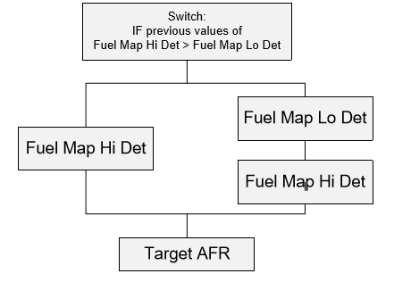
FuelingStrategy 4
IF previous values of Fuel Map Hi Det > Fuel Map Lo Det THEN Target AFR = Fuel Map Hi Det
IF previous values of Fuel Map Hi Det < Fuel Map Lo Det THEN Target AFR = ( Fuel Map Lo Det * Interpolation Factor ) + ( Fuel Map Hi Det * ( 1 – Interpolation Factor ) )
This strategy has 2 maps, Fuel Map Lo Det and Fuel Map Hi Det. If the value in Fuel Map Lo Det is richer than that in the Fuel Map Hi Det then the ECU will use just the Fuel Map Lo Det, otherwise it will interpolate between Fuel Map Lo Det and Fuel Map Hi Det based on the Advance Multiplier.
Tuning
Tune the Hi Det map to be richer than the Lo Det map to make sure the engine gets enough fuel when knock is detected.
Fueling Strategy 5
IF Advance Multipler < Fuel Map Advance Multiplier Threshold THEN Target AFR = ( Fuel Map Lo Det ECO * Interpolation Factor ) + ( Fuel Map Lo Det * ( 1 – Interpolation Factor ) )
IF Advance Multipler > Fuel Map Advance Multiplier Threshold THEN Target AFR = ( Fuel Map Hi Det ECO * Interpolation Factor ) + ( Fuel Map Hi Det * ( 1 – Interpolation Factor ) )
This strategy is also used in vehicles without the ECO mode. In these instances the Fuel Map ECO maps will be omitted and it will revert to Strategy 2
This strategy has 4 maps, Fuel Map Lo Det #1, Fuel Map Lo Det #2, Fuel Map Hi Det #1 and Fuel Map Hi Det #2. The ECU interpolates between the Lo Det Maps or the Hi Det Maps separately, and will switch between them when the Advance Multiplier exceeds the 1D value Fuel Map Advance Multiplier Threshold.
The Interpolation factor between #1 and #2 is based on the Subaru ECO mode. When the car is in ECO mode it will use map #1 (previously named Fuel Map ECO mode), but as you increase engine load and speed it will begin interpolating towards #2.
This strategy is also used in vehicles without ECO mode, in these instances Fuel Map Lo Det #1 and Fuel Map Hi Det #1 are not listed as they are not used in calculation. For these vehicles, tune the ECU in the same ways as strategy 4.
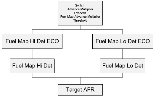
Tuning
Tune the Hi Det map to be richer than the Lo Det map to make sure the engine gets enough fuel when knock is detected. The ECO mode can be set leaner than the Hi Det or Lo Det maps to ensure the engine is running as economically as possible, when the engine goes into open loop mode it will begin interpolating to the richer maps.
Lo Detonation
Lo Detonation map(s) is the main active fuel map under normal engine operation, this map is the base for all fuelling changes. Note that the actual injection time is varied depending on ‘calibration’ maps that are described later in this section. When tuning a car, be sure to scale the Load and RPM data sites as necessary to facilitate the added (or subtracted) airflow values/RPM that you will be using. If either of these values is exceed, the computer will retain the value on the last cell (either Load or RPM, which ever has been exceeded or both). This can be detrimental as there is no longer active fuel control.
This map is used when the engine ‘Advance Multiplier’ is higher than the value in ‘Fuel Map Knock Switch Threshold’ Map.
For most applications, modifying the ‘Lo Det’ fuel map is where most of your ‘fuel tuning’ time will be spent.
Hi Detonation
Lo Detonation map(s) is the main active fuel map under abnormal engine operation, this map is the base for all fuelling changes when severe Detonation has occurred. The cause of which can be due to poor tuning, lower octane fuel than recommended, etc. This map should have similar scaling to the ‘Lo Det’ fuel map(s).
This map is used when the engine ‘Advance Multiplier’ is lower than the value in ‘Fuel Map Knock Switch Threshold’ Map.
For the average tuning, there is not much of a need to modify these values, but you should always check to insure that theses values are ‘richer’ in the higher load/RPM sites than the ‘Lo Det’ map(s).
Idle
Fuelling Engine is idling, which is dictated by two throttle position based maps.
These two maps are located in the ‘Other Maps’ section.
Fuel Map Knock Switch Threshold - Data Values
Determines when the ECU will switch between the fuel maps (‘Hi Det’ and ‘Lo Det’) dependent on the ‘Advance Multiplier’ value.
For standard applications, this map will not need to be changed.
Overrun Fuel
Engine deceleration fuelling controls
Cut-Off Delay
The amount of delay before fuel injectors are ‘switched off’ after throttle is released. At lower RPM and load, this delay time is higher to prevent ‘jerkiness’ at small throttle percentages.
If you are having issue with poor on-off-on throttle response, making these values larger can help smooth the response. As the delay times become larger, fuel consumption will go up (more fuel being used, due to injectors remaining on for longer periods).
Fuelling Restore RPM
RPM at which the fuel injectors are switched back on in relation to coolant temperature. The colder the engine is the more likely it is to stall. To prevent this, the injectors will need to be switched on earlier (higher RPM) to prevent ‘flame out’ as coolant temperature decreases.
Due to low airspeed at idle, coolant temperature is a good indicator of ‘in cylinder’ air temperature.
Fuel Injector Sizing
One or more of these will likely need changing when a larger or non-standard injector is used
Injector Flow Scaling - Data Values
Allows the flow rate of the fuel injectors used to be specified. Due to the amount of variables that calculate actual fuel injector opening time (at the injector) this number does not always equal the actual injector size. It is also important to reduce the Delayed Open Loop Fueling Load Threshold values as these are Injector m/s and will have to be reduced when bigger Injectors are fitted to ensure Open Loop operation is correct.
When changing from standard WRX injectors to ‘pink’ STI injectors, the scaling should be changed from 380cc to 500cc to compensate for the higher flow rate of the injectors. If this is done correctly, then virtually no adjustment of the fuelling maps will be required.
Injector Battery Voltage Compensation - 2D Map
This map controls the injector opening time compensation for battery voltage. Each injector type has different mechanical characteristics, which alters the amount of time that it takes for the injector to open at a given voltage. This map allows the injector lag time to be adjusted when using a non-standard injector.
When changing to non-Subaru injectors, it is quite common to change the ‘lag time’ for the injector to operate properly. EcuTK has set up several dealer forums that are a good resource for finding out Battery Voltage Compensations for most injectors.
Start-up Fuelling
Fuel compensations for starting and warm up periods. It is unlikely that these will need to be changed if the ‘Air Flow Scaling’ and Injector parameters have been set up properly.
Modification of these parameters should only be undertaken when ‘base’ fuelling parameters have been adjusted.
Cranking Fuel
In order for an engine to start, there needs to be enough fuel added to achieve proper atomization.
If the injectors and air flow sensor have been properly scaled, you will not need to make any changes in these maps.
RPM/Cool Temp (AT/MT)
Amount of fuel added by coolant temperature and rpm.
Lower air speeds make it difficult for the fuel to remain suspended in the air stream when the engine temperatures are low.
MAP Component
Amount of fuel added dependent on manifold pressure (absolute).
Throttle Component
Amount of fuel added in relation to throttle position.
There will be less fuel at higher throttle position to facilitate starting when the engine becomes flooded.
Coolant
Amount of fuel added in relation to coolant temperature.
Post Start Enrichment – ‘Warm Up Enrichment’
Amount of extra fuel added after car is started. To prevent stalling after initial start up, extra fuel is injected for a determined ‘time limit’. As this ‘time limit’ comes to an end, additional fuel is reduced.
When this time has expired, the closed loop lambda control is started (if minimum coolant temperature for closed loop has been met).
Throttle Based Acceleration Enrichments (Delta)
Commonly known as ‘Accelerator Enrichments’
Delta
The enrichment factor applied dependent on the delta of throttle movement (%). If the throttle is increased from 15% to 40% (delta is 25%), an enrichment factor will be calculated from the lookup value next to the 25% column. Less fuel will be injected at lower percentages of throttle movement, because the rate of ‘instant’ air flow increase is low, at higher throttle movement percentages, the increase in fuel will need to be much higher, due to the larger amount of air change (which in turn, requires more fuel). The MAF is not able to compensate for the ‘quick in time large air volume’ change that occurs with instantaneous throttle movements.
Too much fuel added to this will ‘bog’ the car when the throttle is depressed, too little will cause the car to ‘buck’.
RPM
The enrichment added at a given RPM. Engine speed based fuelling enrichment/enleanment that is not affected by changes in engine load. This will apply a ‘global’ fuelling change at a given RPM (interpolated) regardless of engine load.
Boost Error
The enrichment applied to the amount of ‘Boost Error’. If desired boost is 2.20bar and actual boost pressure is only 1.5bar (boost error of 0.7bar), then extra enrichment/enleanment may be applied.
Coolant Temperature
The percentage of fuel added during warm up.
Lambda Control
Open Loop will ONLY commence once ‘Delayed Open Loop Throttle Threshold’, ‘Delayed Open Loop Load Threshold’, ‘Maximum Closed Loop Vehicle Speed’, ‘Maximum Closed Loop RPM’, or ‘Maximum Closed Loop EGT’ values have been met/exceeded. Then the time before switchover is determined by the ‘Engine Operation Period Thresholds’ map which determines the value to be used for time delay from the ‘Delayed Open Loop Fuelling’ map.
Engine Operation Period Thresholds
The values on this map represent the amount of time that the engine has been running. These values are used to determine which one of the four sets of values in the ‘Engine Operation Period Thresholds’ is activated. This map is referenced once the other related closed to open loop parameters have been met (Throttle Position, Coolant, Load, Etc…).
For ECUs that are staying in closed loop for extended periods of time when in higher loads (e.g. positive manifold pressures), it is best to modify the map below to speed the ‘switchover time’ and leave the ‘Engine Operation Period Thresholds’ map alone.
Open Loop Delay Period
Determine the elapsed time before the ECU switches to open loop fuelling. There are four sets of values, each one of these sets contains four values. These values are: AT High Altitude, MT High Altitude, AT Sea Level, and MT Sea Level. Which set is chosen is determined by the ‘Engine Operation Period Thresholds’ map, then which value is determined by the transmission type and altitude.
On the USA 2004/2005 WRX, the delay period can be reduced (or set to 0) to speed the time in which open loop is activated. These cars have a much longer delay set to reduce emissions. If large values are left in this table then you may find you have Closed Loop (14.7:1 AFR) on full power for a one or two seconds which will cause detonation and high EGT!
Closed Loop
Closed loop fuelling control allows the ECU to make positive or negative changes to the fuel injection time (trim) to keep the air to fuel mixture at 14.7:1, which for unleaded gasoline is the ‘perfect burn’, creating only carbon dioxide and water as by products. This actual air to fuel ratio will change as the type of fuel is changed, but it is always referred to as stoichiometric regardless of the fuel being burnt.
All of the other maps trigger a time cycle that is determined by the ‘Engine Operation Period Thresholds’ map and ‘Open Loop Delay Period’ maps before switching to open loop (or ‘unregulated’ fuelling control).
Fuel Map Result before Ramping Instead of Jumping
The transitional AFR value used between fast changing Closed to Open Loop. If the engine is held at higher engine speed with low load (Closed Loop – Lambda 1) and then full throttle is suddenly applied the AFR can change from 14.7:1 (Lambda 1) to possibly 10:1 AFR (Lambda 0.70) very quickly. So a transition value of 0.10 Lambda from Lambda 1 will be 0.9 lambda = 13.2:1 AFR.
Max Closed Loop Vehicle Speed
The maximum speed allowed for closed loop control, above this speed the ECU will switch to open loop.
Max Closed Loop EGT
The Maximum EGT allowed for closed loop control, when this EGT is exceeded the ECU will switch to Open Loop.
Not all models are fitted with EGT but it is good practise to reduce these values even if an EGT sensor is absent.
Max RPM
The Maximum RPM the ECU is allowed to use closed loop.
This map can be helpful for obtaining better highway fuel economy at lighter loads. Be sure to monitor EGTs when modifying this parameter. This can also be helpful for disabling the closed loop control of the ECU for Motorsports applications.
Min Coolant Temp
The Minimum Coolant that must be exceeded before the closed loop fuelling will be activated.
Cruise AFR
We are now able to change the AFR that the ECU uses as a reference for closed loop control therefore improving fuel consumption. Use with care though…
Due to the higher EGTs with a leaner AFR, please use caution when changing this value
Load/RPM Target Lambda Offset (MT/AT)
Closed loop AFR offset to allow for richer or leaner AFRs in certain engine load cells.
At lower air speeds, an engine needs extra fuel in order to ignite properly.
Open Loop
When the ECU is in open loop, the ECU no longer makes any trim adjustments. When these values are met, the
ECU will still use the ‘Engine Operation Period Thresholds’ and ‘Open Loop Delay Periods’ map to determine the amount of time before closed loop switch off. Where numerous Throttle Thresholds are available then make sure ALL values are reduced including Auto value and High/Low Altitude values. This is a good practise to adopt in case the ECU ever switches to a High Altitude or Auto Gearbox Mode for some unknown reason.
Per Gear RPM Thresholds (MT)
Gear dependent RPM threshold, each gear has paired values. First gear will be the lower two values, moving up the scale in order to the top two values which will be for 5th gear (or 5th/6th gears on a six speed).
This can be helpful in having a car switch to open loop sooner in lower gears (as the rate of engine acceleration will be faster) on vehicles that have larger turbochargers. Due to this acceleration, the delay based open loop configurations will not have enough time to react.
Stationary RPM Threshold
When the car is stationary, the ECU has the ability to keep the car in closed loop or switch to open loop depending on how these two thresholds are set.
It can be helpful for a competition car that will have standing starts to lower this value. The ECU will be operating in open loop from a standstill, which (when properly mapped) will have stronger starts as no delay time will be used to switch out of closed loop.
Throttle Threshold (MT/AT)
When this throttle angle is exceeded the ECU will switch from Closed Loop to Open Loop mode. Where several values are available set ALL values the same preventing the ECU from using Closed Loop up to higher throttle angles in certain situations.
This can be very useful to prevent the engine from running high boost at stoichiometric fuel mixtures due to exhaust & induction upgrades. Automatic transmissions will typically have a lower throttle threshold due to the amount of load that can be put on the car before positive acceleration is achieved.
RPM Threshold
RPM above which fuelling will go into open loop.
This is often left at higher values, as the RPM thresholds are typically altered in the ‘Per Gear RPM Thresholds” map.
Load Threshold
Specifies the engine load (according to engine RPM) at which the ECU switches from closed loop to open loop fuelling.
Altitude Based Throttle Threshold (MT/AT(Hi/Lo))
The Maximum Throttle angle allowed for closed loop operation; after this Throttle Angle is exceeded the ECU will use Open Loop Mode.
It is strongly suggested that ALL these values are reduced regardless of which gearbox type is fitted.
Idle
Desired Target Idle Speed based against coolant temperature. Where several maps are available for Manual Transmission (MT) , Auto Transmission (AT) , AirCon ON (AC) , High AMPS (High Alternator Output due to High Amperage required to power Heated Rear Windows , Radiator Fans etc).
ALL maps should be increased by the same amount. The ECU is constantly changing to different Desired Idle Speed maps so it is important to change all relevant maps together. Some Idle control parameters are listed under DATA VALUES as well and must also be adjusted.
Target Idle MT/AT 0
Target Idle Speeds for various engine operations.
Target Idle MT/AT ELSE
Target Idle Speeds for various engine operations.
Minimum A/C On (MT/AT)
The minimum allowed Idle Speed RPM for various different engine operation, these should be changed with the 2D Target Idle Speed Control maps.
Minimum High Amps (MT/AT)
The minimum allowed Idle Speed RPM for various different engine operation, these should be changed with the 2D Target Idle Speed Control maps.
Minimum Just After Start Up (MT/AT)
Target Idle Speed just after the engine is started.
Idle Air Flow Map – Coolant Temperature Based
Desired Idle Airflow against coolant temperature, making these values close to your actual Idle airflow values should give better Idle stability.
Idle Engine Load Map – Coolant Temperature Based
Desired Idle Engine Load against coolant temperature, making these values close to your actual Idle Engine Load values should give better Idle stability.
Throttle Angle (into/Out of) Idle
The Throttle Angle Into and Out of Idle Mode.
Ignition
The ‘Advance Multiplier’ is visible from the ‘Live Map Access’ tab when tuning. For Subaru K-Line 2002 ECUs, the value ranges from 0 to 16, Subaru K-Line 2004 ECUs range from 0 to 1.0. When the ECU is restarted, this value (unless otherwise redefined) starts at half of maximum (8 and .5 respectively). This value represents a coarse multiplier of the ‘Ignition Correction Map(s)’. When the ECU has detected no knock, this value will quickly step up to full in quarter increments (based from full value).
A Subaru K-Line 2002 ECU that has been reset will start with an ‘Advance Multiplier’ of 8, if no knock is detected, this value will then step to 12 and then 16 (again, if no excessive engine noise is detected). A Subaru K-Line 2004 ECU would start at .5 after a reset, and move to .75 and then 1.0 if no detonation is heard. This value (for both ECUs) represents the amount of ignition timing that can be added to the main ‘Ignition Base Map’ in accordance to the ‘Ignition Correction’ map. When this value is at 8 (K-Line 2002) or 0.5 (K-Line 2004) then it can use up to ½ of the allowed ‘ignition correction’ in addition to the main ignition map at that load/RPM point. The next step (in a properly tuned ECU) should be 12 (K-Line 2002) or .75 (K-Line 2004), which will allow up to ¾ of the maximum
‘Ignition Correction’, and when to value reaches 16 (K-Line 2002) or 1.0 (K-Line 2004) the maximum ‘Ignition Correction’ can be added. If Detonation is detected by the knock sensor, this value can quickly fall to allow large ‘coarse’ adjustment of ignition timing. This allows the ECU to pull as much as 5 degrees of timing (this is value is dependent on the actual values in the ‘Ignition Correction’ map, without changing the fuel map. In some extreme cases (or a POORLY tuned ECU), the ‘Advance Multiplier’ will drop low enough that boost will be cut and fuelling will be greatly increased to ‘protect’ the engine. The key advantage to this is that it allows the ECU to be quite flexible in a wide range of environmental changes (altitude, fuel, etc...).
We have seen several different approaches to tuning with this dynamic ignition timing control. Some lessen the amount of control that the ECU has with timing, this can be useful if you are running in a static environment or tuning the car for a specific event. Others have increased the amount of control that the factory ECU has, this can work well but be mindful that if a large detonation event happens, the ECU will, in some cases, not be able to remove timing fast enough to prevent damage. What holds true for both methods is a good understanding of the ultimate ignition advance that is able to be run in relation to fuel, altitude, manifold pressure, etc..., and tuning the ECU to meet those parameters (whether it is through dynamic or static ‘Ignition Correction’).
You can use the advance multiplier as a long term knock correction indicator – high values indicate that the ECU is able to use maximum values of ignition advance. Low values will be indicative of a problem that will need sorting (possibly either electrical or mechanical). A good way of checking the stability of tune that is programmed into the ECU is by looking at the ‘Advance Multiplier’ and also observing the ‘Fine Ignition Correction’ table, which will be discussed later in this manual. A properly tuned ECU should always run at the maximum ‘Ignition Correction’ value for the given ECU.
Careful testing is required if these maps are to be modified. When running at higher than normal engine loads, the map may need to be rescaled to further retard timing as load increases beyond the maximum level for a stock car.
Ignition Base Map
This map contains the base ignition map values, based on RPM and calculated engine load. Since the ECU runs highly active ignition timing, the need to make the ‘ultimate’ timing values in the base map is not necessary (unless the ignition correction maps have been modified to allow less timing control). This active ignition control determines the actual ignition timing by both the main ignition map(s) and the ignition correction map(s). There are also other environmental corrections that have an effect on the actual timing (coolant temperature, air temperature, altitude, etc…).
The ECU is designed to actively add timing while the engine is operating, rather than removing timing once detonation occurs. If the base timing specified is too advanced, and the ECU is not able to use positive correction values in several load/rpm areas, the ECU will switch off boost as a safety precaution, since it assumes that there is something wrong.
Ignition Correction Map
This map specifies the amount of additional ignition advance that the ECU may add to the ignition base map. The percentage of this advance that the ECU is willing to use is based on the current value of the advance multiplier (long term knock correction).
Again, the ECU is designed to run advance rather than retard, relative to the base map. Ignition learning will happen more quickly, the closer that the base map is to the ‘total timing’ that the ECU is able to run without detonation at given Load/RPM. When external factors are made more consistent (fuel octane for example), then the values in the base ignition map can be raised. If not, then the base map should be left retarded, leaving the ECU sufficient ability to learn upward using the values in the ignition advance map.
Idle Ignition Timing
The amount of timing that is used when the engine is idling. This value is decreased with in relation to decrease in engine load to smoothly decelerate the engine when returning to idle.
When tuning a vehicle that has a higher compression engine, you will not need as much ignition advance to keep the engine idling.
Compensation
These maps are important to keep the engine consistently in varying environmental conditions.
Coolant Temperature
Ignition offset dependant on coolant temperature while idling or driving. Idle
As discussed earlier, at lower engine temperatures fuel often ‘puddles’ or drops out of the air stream. While idling, this can be exaggerated because with lower air speeds. To combat poor combustion, timing is increased and fuel is added (as discussed in the ‘Fuel Maps’ section).
When idling, there should is no need to reduce timing at higher coolant temperatures.
Driving
While driving, air speeds are greater, which requires more timing advance (less retard) to achieve combustion. However, as coolant temperatures start to rise towards boiling point, timing is reduced to lower in cylinder temperatures. This helps decrease coolant temperatures by lowering the heat which coolant is dissipating.
A poor cooling system (or poor maintenance of) will not be able to remain at the proper running temperatures (with proper fuel mapping) regardless of timing retard. You should always be sure that the other components of the vehicle can handle the additional power output of an ‘up rated’ engine.
Intake Temperature
Allows the ignition timing to be altered based on air temperature. As air temperature increases, the amount of fuel needed for combustion lowers, this requires less ‘burn time’ and so less timing advance. There is NO need for this map to be recalculated when using standard MAF location and air temp sensor.
This map can be quite useful for air temp calibration if the MAF sensor has been relocated.
Detonation Detection
The ECU continuously maintains a table of learnt knock correction. The table is 8x8 in size, with 8 columns for engine load, and 8 rows for RPM ranges. It is possible to alter the dividers between these zones in order to spread the learnt correction across a wider (or narrower) range of load/RPM sites.
When boost levels are raised, the engine will achieve higher loads than were previously possible. In these circumstances, the knock learning load zones may be spread across the new (larger) range of load values.
Knock Detection RPM Range
The Minimum and Maximum RPM range that the ECU is ‘listening for’ and ‘acting on’ Detonation (Knock).
When the RPM limit has been raised, the knock detection range should be raised accordingly.
Knock Detection Minimum Load
The Minimum load that must be achieved before Knock Detection and action will take place.
Knock Retard Decrement
The amount that the timing is retarded when excessive engine noise is detected (detonation). If multiple detonation events occur, this value will be removed from ‘actual’ ignition timing.
Modifying this value can be helpful when running a ‘less active’ advance correction map or ‘race’ fuel, to either ‘dull’ or ‘enhance’ the amount of timing decrement.
Knock Retard Increment
After the ECU has acted on a knock event, it will start to restore timing back to the ‘requested actual’ timing value. This increment value should always be smaller than the decrement value.
A good way to understand how the ECU reacts to a ‘knock’ event is to imagine that the ‘detonation threshold’ is a pot of boiling water. In order to make peak power, you need to keep your finger as close to the water as possible. As you put your finger closer and closer to the water, you’ll begin to feel the temperature rising (similar to using more ignition advance). As the water is boiling, a bubble rises to the surface and touches your finger (detonation). The natural reaction to this is to pull your hand away from the boiling water quickly to prevent getting burned (knock retard decrement). As time passes, you would want to try this again (to achieve peak power), but this time you will approach the boiling water with a little more caution (knock retard increment). To add, ultimately, finding the best distance to hold your finger without being burned (including splashed by the occasional water bubble) would be the maximum safe timing advance.
Ignition Learning
When the ECU is operating in a determined map area, the active ignition learning will be engaged. There are a possible two adjustments that can be made by the ECU at the same time. One is the ‘Coarse’ adjustment, which will quickly add or subtract timing in relation to the ‘Advance Correction’ map. The other ‘Fine Learning’ will constantly be making small long term adjustments as the car is driven. This allows the ECU to adapt to different conditions (either good or bad) quickly and safely.
Coarse Ignition Learning
This allows the ECU to make the largest (coarse) changes in ‘actual timing’ based on multiplication of the ‘Ignition Advance’ map (the description of the ‘Advance Multiplier’ is located in the beginning of this chapter). The ECU will only engage learning of the ‘Advance Multiplier’ while within a predetermined area of the ‘Main Ignition’ map’.
A properly mapped ECU should always be running the maximum ‘Advance Multiplier’ (16 for Subaru K-Line 2002 and 1.0 for Subaru K-Line 2002). If this multiplier is not at maximum, it is a good indicator of a recent ECU reset, poor fuel octane or mechanical problems.
Initial Advance Multiplier
The Advance Multiplier is always set to 8 allowing the ECU to learn before advancing the ignition timing after an ECU reset or disconnecting the battery. It is possible to increase this value to the maximum of 16, be careful, as 100% of the Ignition Correction values will be added to the main Ignition values giving maximum Advance straight after an ECU reset! The Advance Multiplier will still reduce in the case of engine detonation (knock).
When tuning a car for competition use, it can be useful to increase this value so that maximum knock correction will be available when ever the ECU is reset.
RPM Range
This set of values determines the low and high RPM values for ‘Advance Multiplier’ learning.
When the engine RPM will be run higher, it is suggested to modify the upper RPM values accordingly; this will help the ECU ‘recover faster’ if a knock event has occurred.
Load Range
This set of values determines the low and high Load values for “advance Multiplier’ learning.
It is very important to adjust the maximum load values if a higher engine load is achieved over the standard settings otherwise the Advance Multiplier will NOT increase on full power.
Fine Ignition Learning
Fine Ignition Learning is the ‘Long Term’ adjustment of timing advance in small values (can be larger if map was not tuned properly). When the ECU makes changes in this ‘active map’, they will be stored until the ECU has been reset.
The Fine Ignition adjustment table can been seen in ProECU under ‘Live Data’
RPM Range
Similar to ‘Coarse Ignition’, this value indicates the area for RPM sites which the ECU is able to make ‘Long Term’ adjustments.
When the engine RPM will be run higher, it is suggested to modify the upper RPM values accordingly; this will help the ECU ‘recover faster’ if a knock event has occurred.
Map RPM Rows
This Determines the RPM axis of the ‘Fine Ignition Learning’ map.
Both the RPM rows and Load rows together create a grid that overlays the ‘Main Ignition’ map. If, after time, a value is placed in a ‘grid zone’, that value will be added or subtracted from all the sites in the ‘Main Ignition’ map which fall within that ‘zone’s’ area’.
Load Range
Similar to ‘Coarse Ignition’, this value indicates the area for load sites in which the ECU can make ‘Long Term’ adjustments.
It is very important to adjust the maximum load values if a higher engine load is achieved over the standard settings, otherwise the Fine Ignition adjustment will NOT work on full power.
Map Load Rows
This determines the load axis of the ‘Fine Ignition Learning’ map.
As with the RPM rows, you can change the size of each ‘zone’ to fit your particular needs. For example, you can set the lower Load/RPM ‘zones’ to be larger in size than the higher ‘zones’. This would allow the ECU to make ‘Long Term’ ignition adjustments that affect a smaller area on the ‘Main Ignition’ map at higher Load/RPM sites and larger adjustments at lower Load/RPM sites.
Advance Interval
The time delay between fine ignition learning events, modifying this value can make the active timing control of the ECU more or less active.
Lowering this value can be helpful in letting the ECU make fine trim adjustments, which would allow a more dynamic ignition timing map.
Advance Magnitude
The step size of ignition advance that ECU will make when no detonation is heard, this advances applies to the ‘long term’ ignition trim map.
Lowering this value will only allow the fine trim to reduce timing. Due to advance steps available with this trim (~1/3 degree increments); we do not recommend making changes.
Retard Magnitude
When ever a ‘knock’ event has been heard, the fine ignition map will subtract this value from the site in the ‘Fine Ignition Learning’ map. This prevents the knock event repeating itself again and again. If this location specific knock event does not return, eventually the value that was subtracted from the ‘Fine Ignition Learning’ map will be added back in (according to the allowed step size in the ‘Advance Magnitude’ map). When remapping a car, it is always a good idea to look at the ‘Fine Ignition Learning’ map to see how the timing has been modified by the ECU.
Max Advance/Retard
This is the ultimate allowable ‘Fine Ignition Learning’ advance/retard.
There should be no need to modify these values.
Switching Maps
The ‘Advance Multiplier’ is used by the ECU as an indicator of potential problems, and therefore referenced to switch between maps and to cut boost if something has gone wrong.
Fuel Map Knock Switch
Determines which Fuel map is used (Hi Det/Lo Det), at or below this value, the ECU will use the ‘Lo Det’ fuel map. This feature helps reduce EGTs, when a problem has been recognized. It is important to scale the ‘Lo Det’ fuel map properly so that if this threshold is met, the fuelling can be increased as necessary.
Learnt Ignition Retard for Boost Disable
The magnitude of learn ignition retard required to disable the wastegate solenoid.
Learnt Ignition Count for Boost Disable
The number of learnt ignition retard values of a high negative value required to disable the wastegate solenoid.
Advance Multiplier for Boost Disable
When the ‘Advance Multiplier’ lowers down to this value (or below) the boost control will be disabled.
Advance Multiplier for Boost Re-Enable
Boost control will be reactivated when the ‘Advance Multiplier’ reaches this value (after ‘Advance Multiplier Boost Disable’ has been activated).
Limiters
RPM
Two stage engine rev limit. The first value is the RPM at which the rev limit begins. The second value is the RPM at which the rev limiting switches off again. It is advised that these two numbers are set at least 200rpm apart so that the engine speed must drop by 200RPM before the rev limit switches off.
RPM Ignition Retard
When rev limiting, some ECUs allow additional ignition retard to be applied. This parameter specifies this retard value.
Road Speed
This map allows adjustment of vehicle speed limiting. There are 4 values associated with speed limiting. Two values are for manual transmission, whilst the other two are for automatic transmission. Of each pair, one value is the speed at which limiting begins. The second value is the speed to which the vehicle must drop before speed limiting ends. The values are arranged in the following order:
Automatic Transmission Speed Limiting Start Speed
Manual Transmission Speed Limiting Start Speed
Automatic Transmission Speed Limiting End Speed Manual Transmission Speed Limiting End Speed
Sensor Scaling
Main Control Maps
Air Flow Sensor Scaling (MAF)
Determines how airflow sensor voltage is converted into an airflow rate value. This map may be modified if the car is fitted with an induction kit that alters airflow, or a non-standard air flow meter. To correctly achieve this, requires flow testing and measurement of the new devices.
Air Flow Sensor CEL
Specifies the airflow rate at which the check engine light is illuminated. Modification is not necessary unless extremely high flows are to be encountered.
Mass Air Flow Reading Limit
The maximum Mass Air Flow reading is 300 or 400 gms/sec on Subaru K-Line 2002, this is a limitation of the ROM file not of EcuTek software. Subaru K-Line 2004 is not limited.
MAP Sensor
Map sensor is used for closed loop Boost Control , Atmospheric Pressure reference checks and can also be used for Fuel and Ignition compensations depending on exact ROM file version.
Misc.
Radiator Fan Control
Four values control radiator Fan ON and OFF temperatures , varies for each model , watch for twin fans where all four values can be different.
Intercooler Auto-Wash Thresholds
For vehicles fitted with automatic intercooler water spray, these thresholds for coolant temperature, RPM, boost pressure, vehicle speed & air temperature control when the water spray is switched on. All of the criteria must be met for the spray to be enabled. Each parameter, such as RPM, has two threshold values. There are 2 values to implement hysteresis.
- Coolant Temperature - Minimum coolant temperature required for IC Spray operation.
- RPM - Minimum Engine RPM for IC Spray operation
- Boost Pressure - Minimum Boost Pressure for IC Spray operation
- Vehicle Speed - Maximum Vehicle Speed for IC Spray operation
- Air Temperature - Minimum Intake Air temperature for IC Spray operation
Special ROM Features
EcuTek have released a number of specialised ROM files that provide extra features to both the tuner and to the driver. This chapter describes how to make these features available in tuned ECUs
Compatibility & Prerequisites
These special features are provided in two ROM versions:
AF423 – Suitable for use in MY02-MY03 US WRX vehicles. This ROM file is named AF423-MapSwitch.
AF531 – Suitable for use in MY01-MY04 European and Australian WRXs. This ROM file is named AF531-MapSwitch.
AG820 – Suitable for use in MY01-MY04 European and Australian STI models. This ROM file is named AG820-MapSwitch.
AH591 – Suitable for use in Japanese STI models. This ROM file is named AH591MapSwitch.
The above ROM files will support 99% of encountered Impreza vehicles. Other ECU versions, such as Subaru KLine 2004 ECU versions with Drive-by-Wire (DBW), are not supported at this time, though may be supported in the future.
The latest version of Subaru K-Line 2002 is required for access to ‘Feature Selection’ option described below.
The latest version of DeltaDash is required for access to ‘User Tuning Adjustment’ features shown below.
Feature Selection by the Tuner
The following user tuneable features may be enabled or disabled by setting or clearing bits in the ”user configuration data value”, accessible via Flash2002 in the “Data Value” maps section.
| Bit | Value | Function |
|---|---|---|
| 0 | 01 | Idle Speed Adjustment |
| 1 | 02 | Rev Limit Adjust (Valet Mode) |
| 2 | 04 | Overall Ignition Adjustment |
| 3 | 08 | Ignition Learning Adjustment |
| 4 | 16 | Boost Pressure Adjustment |
| 5 | 32 | Duty Cycle Adjustment |
| 6 | 64 | Open Loop Fuelling Adjustment |
| 7 | 128 | Boost & Duty Map Switching |
Simply add the above values together for the features that should be enabled and enter the total in the user tune configuration data value from Flash2002. This allows only the features required to be enabled to achieve the required result. The features selected will then be accessible via DeltaDash.
An example of this would be that if you wanted to allow the User Tuner to have access to all features then enter FF in the “User Tune Config Byte” in “Data Values” in Flash 2002. If you wanted the features Overall Ignition Adjustment, Ignition Learning Adjustment, Boost Pressure Adjustment, and Duty Cycle Adjustment then add the numbers 04 + 08 + 16 + 32. This adds up to 60. Then enter this value in the USER TUNE CONFIG BYTE
User Tune Feature
This new feature allows the car owner to subtly alter the configuration of an ECU supplied by an EcuTek dealer. Parameters such as rev limit, fuelling, ignition timing and boost pressure may be altered for situations such as racing on high octane fuels, adjusting boost control for unusual atmospheric conditions and dropping the rev limit before leaving the car with a valet. All of these features are available via DeltaDash.
As well as being of interest to the customer, these live tuning features may be used to assist in producing tuned ROMs. For example the live adjustments of boost control parameters may be used to select values for the boost and wastegate duty maps for the final ROM file - these features can be used to find the duty required to produce a given boost
Note that these changes may be done live – yes, while the engine is running! The changes remain until the ECU is reset.
To utilise this feature, one of the above specified ROM file versions must be programmed into the ECU, since the standard ECU does not contain this functionality.
Map Switching Feature
Switching between pairs of boost maps and the configurable rev limit are available from the dashboard. To toggle between the two sets of maps, the driver simply holds full throttle and engages the rear demist switch, while the ignition is on. This can be while the car is stationary or while the engine is running
The feature is implemented using the manual and auto pairs of boost and wastegate duty maps. The two performance levels are determined by the data placed in the two sets of maps. Switching maps swap between auto and manual, and back again.
As well as being possible to switch maps from the dashboard, this may also be done from DeltaDash using the User Tuning feature shown below.
To utilise this new feature, one of the above specified ROM file versions must be programmed into the ECU, since the standard ECU does not contain this functionality.
User Tuning Feature Descriptions
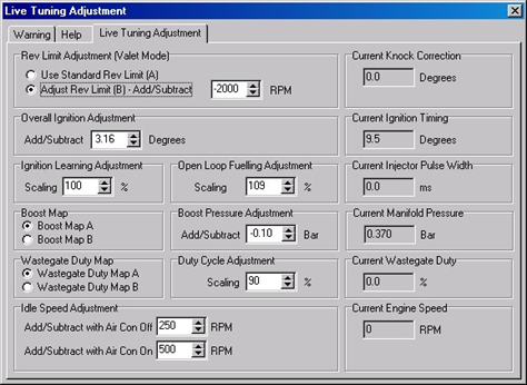
The screen shot below shows the user-tuning window available via DeltaDash.
Depending on the features selected by the tuner (via the User Tune Config Byte) not all these features may be available.
Idle Speed Control
Allows a wide idle speed rev range.
Rev Limit Adjust
Allows adjustment of the rev limit used when in valet mode.
Base Ignition Adjust
Allows up to 5 degrees of timing to be added or subtracted from the base ignition timing. This is useful when running race fuel, or tuning on the dyno.
Ignition Learning Adjust
Scales the result of the ignition correction map lookup. Allows ECU to learn higher timing. This is useful for higher octane fuels. I.e. setting this value to 150% would give 50% more maximum ignition advance over and above the base map.
Desired Boost Adjust
Allows up to 5 PSI of boost to be added or subtracted from the desired boost curve.
Max Duty Adjust
Scales the maximum permissible wastegate duty. Useful for achieving higher boost specified with the desired boost adjust, or to calm down unstable boost in very cold weather.
Open Loop Fuel Adjust
Adjusts the open loop air/fuel ratio. This scales the ‘percentage over stoich’ quantity. E.g. if the ECU is running 12.7:1, then that is two points over stoich. If this were scaled to 50%, then the ECU would run approximately 13.7:1.
Boost & Duty Map Switching
Allows switching between pairs of boost and duty cycle maps. Boost and duty maps labelled ‘A’ to the user are the auto maps when edited from ProECU. Maps labelled ‘B’ are the manual maps.
Valet / Map Switch Mode
This is perhaps the most interesting feature to the average customer. This allows the driver to switch boost, duty and rev limit from the dashboard controls. By default, the ECU runs standard rev limit plus boost and duty maps ‘A’. Toggling valet mode switches to custom rev limit plus boost and duty maps ‘B’. Since the rev limit is configurable via DeltaDash, the customer may use this as a safety feature to prevent a second driver from using high revs and consequent vehicle speeds. Alternatively, the customer may leave the rev limit standard and the tuner may use the feature to provide two separate performance levels.
Holding full throttle and pressing the rear defog button toggles valet mode. This may be done when the engine is off or running, so long as the ignition is on at the time.
Configuration Persistence
These new features have been configured to reset to neutral values whenever a standard ECU reset is requested via the diagnostics port from a select monitor or DeltaDash. However, unlike other ‘programmed’ tuning, any of these parameters may be altered while the engine is running via DeltaDash, making adjustment live, quick and simple.
EcuTek ProECU tuning tools tools should only be used by experienced tuners who understand the product and engine calibration.
If you do not fully understand this product then you WILL damage your engine, ECU or your vehicle.
Please ensure you fully read all EcuTek manuals BEFORE attempting to use ProECU with your laptop or your vehicle.
Use with extreme caution and understanding at all times, if in doubt then do not proceed.
EcuTek accepts no responsibility for any damage to the engine, ECU or any part of the vehicle that results directly or indirectly from using the product.
** If you are in any doubt that you do NOT have the experienced required to use this product then you should NOT USE IT **
Retail customers
** If you have any doubt that you do NOT have the experienced required to use this product then you should NOT USE IT, you should simply contact your EcuTek Master Tuner shown clearly on the top of your Programming Kit or visit your preferred tuning shop to have a professional tuner to use it for you **