B58 Tuning Guide
- Paul Blamire
- Chris Todd
- Brandyn Mowat

ProECU Tuning Guide
Introduction
Throughout the development of the platform, we've done our best to properly sort maps in a clear and concise manner. This gets especially important on the B58 because there are 1000's of OEM tables that exist in the ECU. As such we've taken a few steps to pull out the most important items.
Usually, in the root of each folder tree, you'll find the most important tables without needing to expand any additional sections. That's not to say that some tables you'll want or need won't be in those spaces, but if you're looking for a good place to start those are usually going to be the maps you want to try.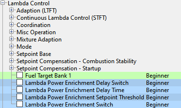
User levels were also set up so that most of what you'll need for a "Stage 1" tune will be found in the Beginner user level.
Supplemental Content
Platform Specific
General
Table of Contents
The sample Stage 1 ROM has around 150 changed maps. A reasonable stage 1 tune is only around 60 map changes, with 10 or so being adjustment to flags for protections.
- Boost target
- Clutch Torque Max
- Component Protection Removal
- Target temp for EGT with catalyst tweak
- Fuel map
- Normal Ignition map (Can be tweaked. If you change the fueling, torque limits can cause DTC)
- From a function monitoring standpoint of the ECU checking itself you'll need to raise some limits like the torque limit so that the car isn't capable of hitting it.
All in all while How you make the changes may be a bit different from the more simple vehicles. You'll still want to make the normal changes as on any other car, raise boost, lean fueling, increase timing. If you want more torque, ask for more. If you aren't hitting the torque you need to hit, add load. If you aren't getting enough load then ask for more boost,
Summary of Software
Torque Control
To some degree, the B58 ECU is almost entirely torque-based. Some level of torque is set (i.e. a driver torque request from the accelerator pedal) that level of torque is then sought after from the engine side. It then gathers torque requests from the other tables and goes after the lowest torque maximum.
Some tables are measured in Indicated Torque also called combustion torque. This is an amount of torque achieved assuming there are no losses from friction etc. as if it were running under reference conditions. Essentially if you were running at Lambda 1 (14.7:1 stoich) and you were at optimal timing this is the torque you would have before losses and is essentially a level completely related to airflow. All calculations for airflow, ignition timing and boost are one based on Indicated Torque
Other tables are measured in Clutch torque, which is a measure of the torque at the flywheel. This is the engine's torque after compensations for frictional losses. Not to be confused with torque input to the gearbox as that comes from the torque converter / Manual transmissions. This applies to both automatic and manual transmissions.
There are additional tables that establish the torque loss from friction, Air Conditioning, The alternator and other sources.
The Ignition Optimum Timing maps are the amount of ignition timing and RPM at which the reference torque would be achieved.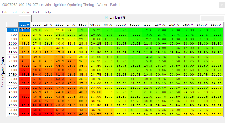
The maximum torque level for a given state is scaled through the pedal position torque request in order to get the desired output torque. From there it gets turned into the desired load via the indicated torque to load table (which utilizes RPM as the x-axis and engine load (cylinder fill) as the y-axis) Keep in mind 100% is sea level air pressure.
There's no additional table handling the conversion from load back to torque for the ECU, it goes through the same torque to load table in the other direction.
If you raise torque numbers and not load, you’ll get less load. The same torque request then results in a lower load output. If you want to accommodate higher load, you’ll scale up the load.
Torque Requests
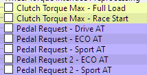
Clutch Torque Max - Full Load
Runs a limit on the Driver Demanded Torque from the Pedal Request maps.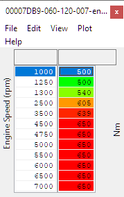
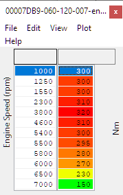
Clutch Torque Max Race Start
Limit for driver demanded torque during launch control
Clutch Torque Maximum
The base torque limit of the engine, as scaled by driver demand.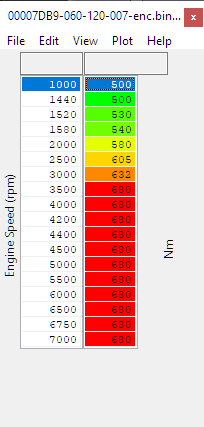
In situations where you request a high amount of torque in high RPM that can't be achieved (if it is unable to hit the load level required for the amount of torque), rather than trying to get the torque from somewhere else (advancing ignition etc.) the torque request will get dropped down to what is being achieved. Similarly if you aren't hitting the boost required to hit your load request, it will reduce your torque request. If your load is limited due to the load limit or maximum boost pressure, the torque request will become whatever you achieve at the load limit. The relationship between torque request and cylinder fill desired is always trying to be maintained. This is one of the reasons tuning a vehicle with a manual wastegate can be challenging.
Torque request=Pedal Request x Clutch Torque Max - Full Load (driver demand) as checked by the limit of Clutch Torque Maximum
Indicated Torque To Load (Cylinder Fill)
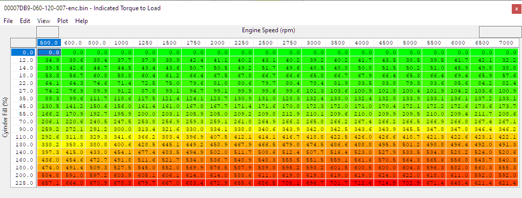
Two way table that establishes the load request for a given torque request and converting load into torque values.
Calculating Indicated Torque
Indicated torque is calculated from engine speed and cylinder fill. The result is used to further calculate the clutch torque figures used in limitation for all aspects of the driveability of the car such as driver demand and gearbox protection.
Calculating Cylinder Fill
Going the other way a corrected clutch torque request (indicated torque) and RPM value go in and establish the cylinder fill request for the given amount of torque.
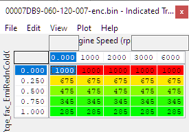
Regardless of load limits the Cylinder Fill Desired will be capped at the maximum value in the Y axis of this map (220% by default), making it an important map to edit in almost all cases. When increasing the values in the Y axis you'll want to increase the torque values and typically in a proportional amount in order to request more power and maintain correct torque estimation.
If your potential target Cylinder Fill results in an indicated torque of more than 1000Nm the torque output will be limited, the solution is to further increase the Cylinder Fill values while keeping the indicated torque at or below 1000Nm. In these cases where cylinder fill is increased more than the requested torque values we refer to it as "Understating the Torque" and can be helpful for big power big turbos where Cylinder Fill can exceed 260%.
It has not been uncommon in the past to only alter the highest value in the Cylinder Fill axis of this map to give increased load and boost. Just remember that this has to do with the torque values sent to the transmission and shown on the gauge as well as other calculations so while it’s a fast and dirty way to do it, and can cause some bad side effects. The difference in gearbox operation between telling it you’re making 700-800 nm vs 550 is quite noticeable in terms of the way the transmission shifts. So the best way to do it is to scale both the load and the torque equally, as much as is possible.
There is a limit on the torque of 1000nm in the cells, so about a 25% increase in load and torque is the most you can make it linear-ish.
Limits on indicated torque
Map List
Torque - Driver
Torque - Engine
Live Data Parameters
Due to the impressive number of maps and monitors on this ECU, we've only listed the most common ones above.
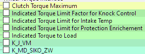
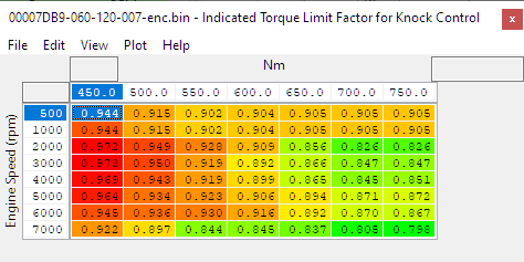
Indicated Torque Limit Factor for Knock Control
Indicated Torque Limit for Intake Temperature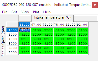
Indicated Torque Limit for Protection Enrichment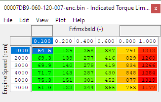
These are limits on the indicated (combustion) torque. In the context that it represents the sort of torque that is created by pressure in the cylinder, (the kind of load that is indicative of the pressure in the cylinder) we realize it is the type of load that can do damage through bending connecting rods, pistons etc. This means it’s a good idea to establish safe limits to protect the engine components. You wouldn’t want to set these the same as your clutch torque limits since your reference(indicated) torque is always higher as you aren’t always running MBT. So even with a 500nm clutch torque limit, for all intake temps up to 65 it’ll be at 800 stock. Bumping it up some at safe temperatures is a good idea. The intake temperature limit will cap the incoming value going into the indicated torque to load.
One difference between USDM and EDM Roms is when looking at the component protection. The USDM rom has component protection maxxed out wherewas the UK ROM has actual values input into it. The top axis is component protection limiting factor from .1 to 1
You’ll get the net limit of all these elements as they combine It’s good to be familiar with these limiters and the type of torque they’re limiting.
Indicated Torque Limit Emissions Reduction
Will apply a torque limit while the vehicle is warming up to avoid damage to catalyst or GPF if equipped.
Max Torque Flags
For a list of the torque limits you may see while running the vehicle see our article B58 / Supra Limit Flags & States
In terms of the Torque Overall category it aggregates all the torque calcuations throughout the drivetrain before it goes to the engine torque, including max wheel and gearbox torques. There are various flags to remove certain inputs, the common example is a transmission torque limit of 550Nm, which will limit Torque Request regardless of demands and limits in the ECU calibration, and Torque Limitation State will be 1048576.
Max static torque is steady state torque. I.e. you’re making 600nm at steady speed it will be corrected by this. Dynamic refers to rapid speed changes so if you’re accelerating at maximum you’ll have less torque at the gearbox due to the inertia effecting the engine. (why a lightweight flywheel can impact torque at the wheels). Rapid speed changes due to gear shift can also show up in dynamic torque. Not all of them are enabled by default.
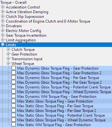
These flags will stop higher torque requests from limiting your torque demand.
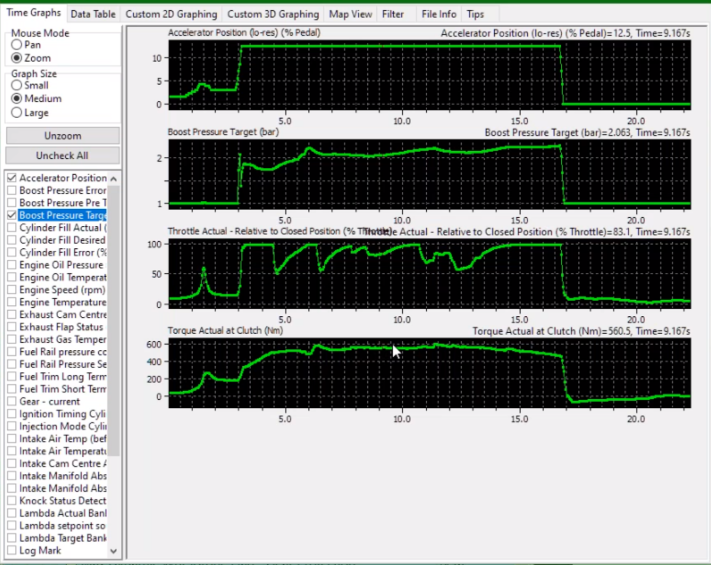
You can see any time we get a significant jump at torque that the throttle closes. As the torque drops you can see the throttle come back up. This is alleviated by turning the flags off.
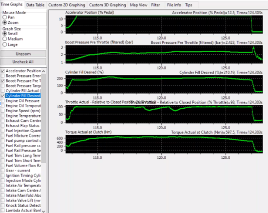
Getting much more cylinder fill, throttle isn’t closing as much (there are still some for boost control and shifting)
Removing Limiters and Flags
While tempting, turning off all of the limits and flags can result in damage to the vehicle, so setting them to sensible values or leaving things like torque reduction on gear shift can result in a safer tune, with a lower likelihood of damage ot the vehicle.
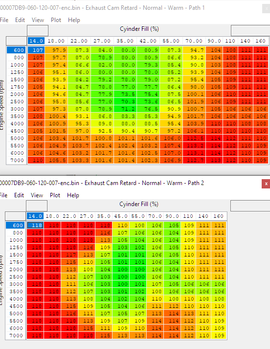
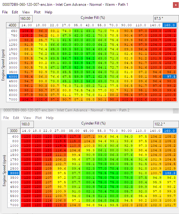
Camshaft Timing
At light load the system utilizes the VVL cam timing to control airflow. At medium load the throttle is utilized, and at high load boost control is the main way it controls the airflow through the engine.
The commonly used tables are the Normal - Warm - Path 1 / 2 for intake and exhaust cam timing. The engine swaps between the warm and cold tables based on engine temperature.
Map List
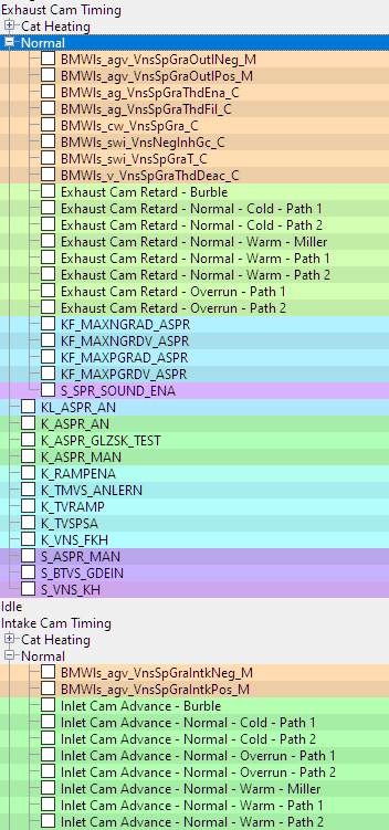
- Exhaust Cam Retard - Burble, Normal, Overrun
- Inlet Cam Advance - Burble Normal, Overrun
Fuelling
If there are any issues in the fuel system there is also an extra load limit which will start ramping down the load limit if the HPFP or available injection is maxed out. While this typically won't happen on a stage 1 car, ethanol and it's increased fuel demand will likely cause it to start hitting those limits.
Setpoints - base target, lambda enrichment, component protection (with temperature targets/limits) etc
Fuel related Load limits - injection limit triggered, HPFP triggered, low pressure pump triggered
Injection phasing (related to load limitation via injection limit)
Lambda Control
Normal behaviour is to run lambda 1 (Given the stringent emissions requirements these days except for when it's in component protection). If the engine or exhaust components get very hot then it the component protection system will initially set the lambda using the main fuel map and ramp it progressively richer until the temperature is with normal limits.
As a base level of operation, the vehicle will either run at lambda 1 until it runs into component protection, or will target your richer fuel target for the duration of the delay time and then go back until lambda 1. If you demand power you hit power load enrichment SOME times but still likely results in the target of lambda 1.
Generally the map changes you’re looking at surrounding the adjustment of power and load enrichment so that it will run the base lambda target without running in to component protection. You can set a floor for target lambda minimum and that will stop component protection from targeting that lambda, but that doesn’t stop component protection from being on. So even though your lambda is where it wants to be, component protection is sill active and ramps down the load limit on other tables. It’s a good reminder that you need to set appropriate limits and making sure the ECU isn’t hitting those. I.E. if you were to set component protection at 3000 degrees it will stop component protection from doing much of anything (Albeit at the expense of a working component protection system.)
At the extreme end of component protection when it’s looking at EGT and max cat temp it can make additional changes to the maximum turbine temp.
Fuel Target Bank 1 (or RaceROM Equivalent for additional Resolution)
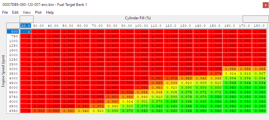
If the lambda power maps are set up as suggested below, the vehicle should operate off of these lambda targets under the majority of conditions.
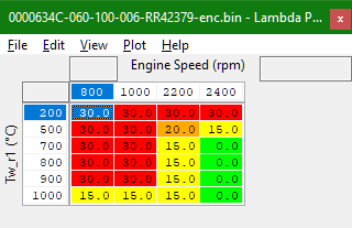
Lambda Power Enrichment Delay Time
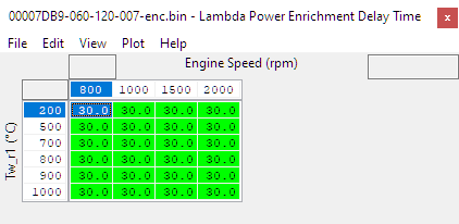
There is a background timer where after the timer expires it will be on that map. Letting off the throttle will only pause the timer not reset it as there is a delay to the delay being reset.
The longest amount of time your car will run on the leaner Enrichment Setpoint Threshold as long as it doesn't hit any limits or component protection. If you lower the timer it will hold a target for the duration of the Lambda Power Enrichment Delay Time before returning to lambda 1 unless your temperature exceeds your component protection temperature limit.
Use the screenshot below as an example for changes you'll want to make in instances where you'd like a faster changeover to a richer target, or in some cases instant switching (0).
Lambda Power Enrichment Delay Switch
Set to 0 (may already be that way in some cars)
Lambda Power Enrichment Switch
Set to 1 to allow targets richer than lambda 1, otherwise it will always use the timer and never jump on to your actual fuel map Fuel Target Bank 1 unless component protection is triggered.
Lambda Power Enrichment Setpoint Threshold
This is the lean lambda target that gets used before the transition to the rich lambda target based on the lambda enrichment timer.
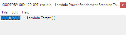
Set this to the leanest value you want to run out of "lambda 1", typically Lambda 0.9, do not set this to a rich value.
Fuel Rail Pressure
Target fuel pressure is 35mpa under load set under the Fuel Rail Pressure Target Cold / Warm. Temperatures for the switching point for map use are set by the Fuel Pressure Cold / Warm Threshold maps. Slightly dropping the pressure target around peak torque can avoid overloading the pump when demand is high.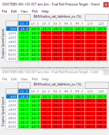
If the High Pressure Fuel Pump hits the maximum available angle of 126° designated by BMWinjmon_ag_HppSpMax)M (maximum physical angle) it will start to lower the load limit to the value found in Load LImit Minimum Injection Monitoring. Even so most of the time pressure only drops to 260 bar or so.
The maximum physical angle for the pump is a physical limit, you'll only want to change the value if you're using a pump with a different number of lobes.
Injection Phasing
There are around 70 different injection angle maps.
IP1EOI (And Latest EOI for SOI based Pulse
Sets the latest end angle value for a SOI pulse in order to calculate the maximum injection window. At higher load and RPM you may want to reduce the value to give a large enough injection window to better control the final air fuel ratio.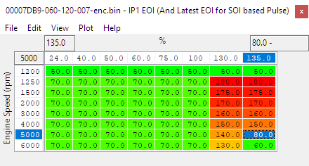
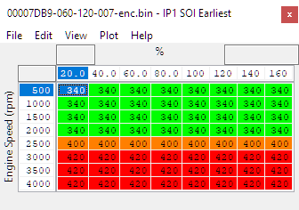
IP1 SOI Earliest
Sets the earliest point in the engine's rotation for the start of injection.
IP1 SOI Normal Cold/Warm
Establishes the starting angle for start of injection when the engine is cold/warm.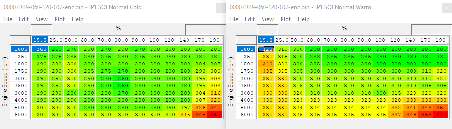
Ignition
The ignition timing consists of a Normal map and a Safe map that it interpolates between. After going through those it applies corrections (such as knock), then it goes through torque intervention tables, then down to the minimum limit.
Two sets of maps, Normal and Safe for Path 1
Path 1 = Normal operation with VVT and boost load control active (almost always used)
Path 2 = Throttled mode (almost never used)
Normal maps are mostly used when the car is put in Sport mode, with a warm engine and normal running conditions
Safe maps are mostly used when in non-Sport modes, or with a cold engine, and sub optimal running conditions (high risk of knock, high back pressure, low octane and other factors). The ECU doesn't switch between the two, it blends and is given by the live data parameter Ignition Blend Factor. It is determined by a complex function using many comparisons, maps and values, and adjusting it's behaviour is beyond the scope of tuning with ProECU.
Map List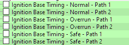
RaceROM Switchable Maps
Live Data Parameters
- Ignition Timing Cylinder (1-6) - Actual Ignition Timing on a per cylinder basis
- Ignition Blend Factor - Interpolation between Normal and Safe ignition maps, 100% = Normal, 0% = Safe
- Knock Retard Cylinder (1-6)
 - Short term knock correction on a per cylinder basis
 - Knock Retard Average - Average value of the per cylinder knock retard
- Knock Retard Total - Sum of average knock retard, temperature retard and long term knock adaption
- Used in multiple Load Limit Tables as X-Axis
- Used in multiple Load Limit Tables as X-Axis
- Ignition Timing - Final timing value for cylinder 1 with one degree resolution
- Ignition Target from Torque Intervention - Target ignition angle as a result of torque reduction, from a gearshift for example
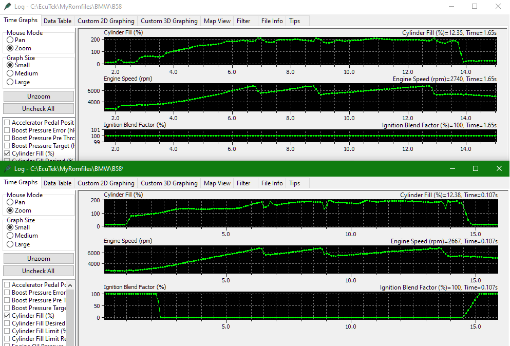
The screenshot below shows the same car running in sport (top graph) and normal mode (lower graph) and the difference can be clearly seen.
Most tuning of ignition timing is done just by adjusting the values in the Normal and/or Safe ignition maps, and the values in these maps are the knock limited ignition advance when running at normal intake and engine temperatures, using the highest octane fuel the engine is designed to run on (98RON by default). The ECU will not try and use more ignition advance than is calibrated in these base maps, and all corrections are in the form of retard from these base values.
EcuTek RaceROM adds more maps to use with map switching with increased axis points to easily account for increased load and RPM, but they behave in exactly the same way as the OEM maps. Any RaceROM enabled ROM will always use the RaceROM versions of the Path 1 ignition base maps.
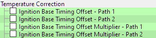
Ignition Base Timing Offset - Path 1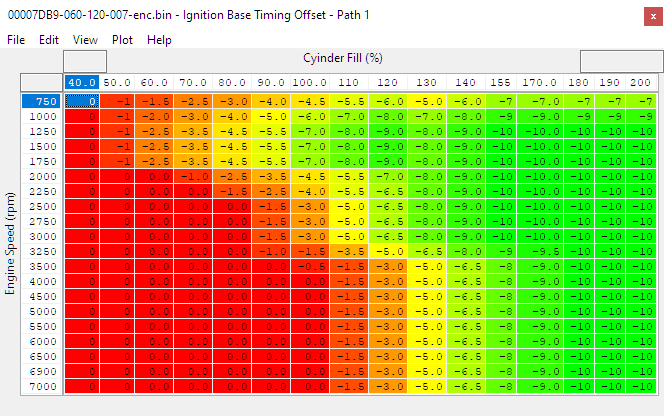
This map defines the maximum possible ignition adjustment to the base ignition for temperature correction
Ignition Base Timing Offset Multiplier - Path 1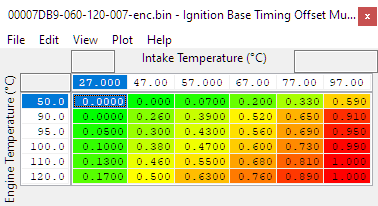
This map multiplies the result from Ignition Base Timing Offset - Path 1 to introduce a final amount of retard to the base timing from the Normal or Safe maps. This retard is included in part of the RaceRom logging parameter Ignition Retard Total. and can easily reach 5 degrees at the end of a dyno pull or run though the gears on the road.
Knock Control
These cars don't have any big issues with knock control on regular (good quality) fuel, the stock maps keep the engine safely on the edge of knock situations not overreacting engine noise. Like most knock control, detection is looking at a smoothed average of normal values, and subtracting that value from the current live value. The knock thresholds are the main maps used in tuning.
Knock Threshold Cylinder (1-6)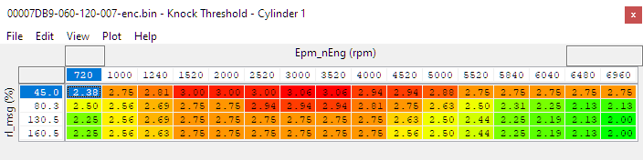
That being said you may run into issues when you begin to run ethanol, our RaceROM FlexFuel strategy adds ethanol specific maps that can be blended between based on ethanol content to avoid reacting to "phantom knock noise"
When tuning the B58 it's normal to experience some knock retard from time to time. When tuning for maximum power you should expect some cylinders to retard as much as 3 degrees when under heavy, sustained load, even though the temperature correction will also be retarding 4-5 degrees at high intake temperatures. Reducing the base timing to avoid any knock retard on all cylinders at all times will normally just cost you power.
If you are new to B58 tuning, it's good practice to log a standard car and pay attention to Ignition Timing Cylinder (1-6) values to appreciate what is "normal".
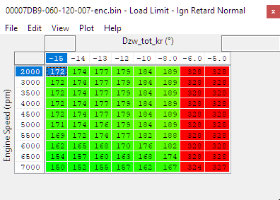
Load Limit Ign Retard sport/Normal applies a load limit based on Ignition Retard Total and can be used to reduce load and boost in addition to the retard, we recommend not to fill these tables with a maximum value, but instead use them to help save the engine in case of unexpected sub-optimal conditions such as poor fuel.
Limiters
Vehicles from different regions have different component protections enabled for variances in regulations and equipment. For example European vehicles don't have load limits for component protection, additionally USDM vehicles don't have gas particulate filters and thus don't have the protection tables for those.
For more information on specific load and torque limit flags check out the complete list B58 / Supra Limit Flags & States
Rev Limit
Applies a different limit on RPM under different conditions such as temperatures going over desired, sensor failures, the presence of knock, or issues with the emission system.
Load / Cylinder Fill
Turbo / Boost Control
Basic Boost Control Process
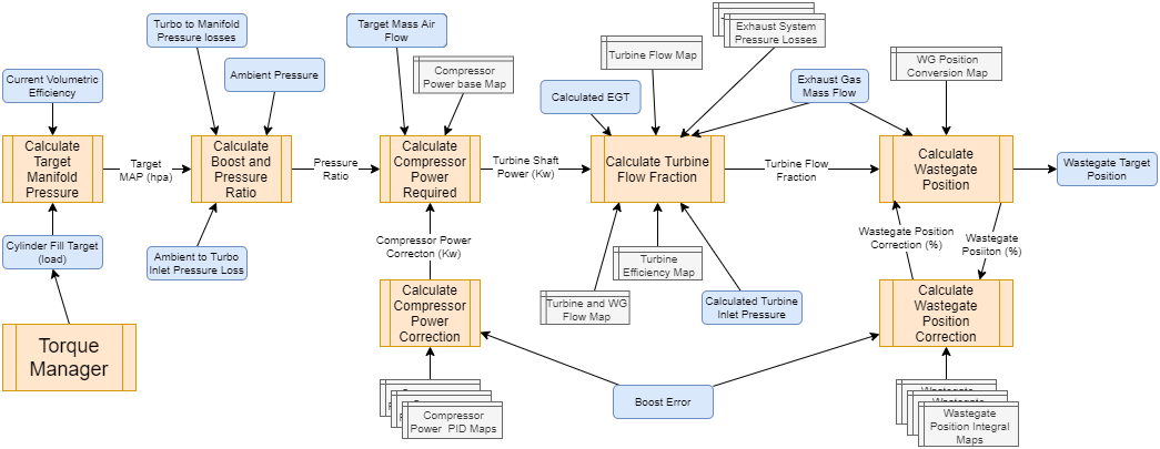
Like many modern ECU boost control strategies the B58 is built around the power required by the compressor wheel to generate a pressure calculated to meet the needs of the airflow that will deliver requested torque value, accounting for the current operating conditions. As the target airflow increases the ECU will already know it needs to increase the drive to the compressor wheel, and will calculate many of the changes required before converting these to a wastegate duty cycle and fine tuning based on the boost error.
All B58 platforms also use an electronic wastegate, and the control loop uses "duty" to mean position where 100% is fully closed and 0% is fully open. It's important to understand that in this case 100% position is not the same as 100% duty on a pneumatically controlled actuator! To appreciate how different this can be, consider a boost solenoid at 0% duty while a turbo is making less boost than required to move the actuator, in this case the wastegate position is effectively 100% or fully closed. This also applies at the other end of the spectrum, a pneumatic actuator being driven by a solenoid valve at 100% may still result in a wastegate that is perhaps 10% open, in this case the duty is 100% but the actual position is still only 90%.
Do not use 100% position as the maximum effective position for boost control at high power! This will result in less than maximum available power and the ECU will consider this an error state and open the wastegate after a brief time delay.
Boost Targets
The boost target is calculated from the desired airflow using the same maths employed to calculate airflow from pressure, engine speed, cam position etc. There is no target boost map, and in general to increase boost, increases in torque and/or load requests need to happen. However it is possible to limit the maximum requested boost, which can be done for engine protection, turbo protection or control limits.
This can have some interesting side effects. For example without making changes to the torque limit, the boost target can be significantly reduced when high octane fuel is used and ignition timing significantly advanced, as the ECU will adjust the boost target to deliver the same torque.
If boost target is appropriate, but the boost isn't on the target, this usually means there are boost control maps that need to be tuned. In many cases it becomes a simply getting the boost to reach the ECU's own calculated target in order to achieve the tuning result. It is important to keep in mind that the limits for boost target must be sufficient to allow for the target power.
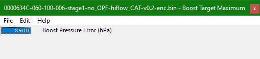
Boost Limits
The maximum targetable boost is limited by Boost Target Maximum and in normal circumstances a load limit will also be calculated (with Cylinder Fill limit reason #2) that corresponds to this boost level. Even if using RaceROM boost limits, this will need to be raised to allow sufficient headroom for the anticipated boost levels.
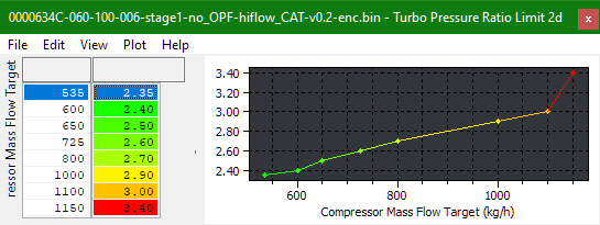
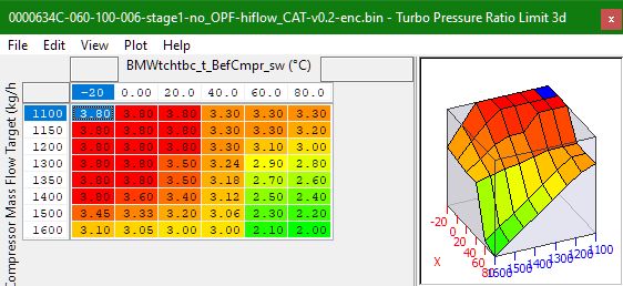
Compressor Pressure Ratio limits (2d & 3d)
There is also a limit on the compressor pressure ratio that will be converted to an absolute pressure limit, and also a load limit. There are two maps using different input parameters, and both will need raising for significant power increases, especially at altitude.
In high altitude locations (for example Boulder, Colorado where the ambient air pressure is 850mbar) even a moderately high boost pressure of 2500mbar (absolute) results in a pressure ratio of 2.94 which will definitely be limited by the stock maps when the intake temperature rises over 40ºC.
Map List
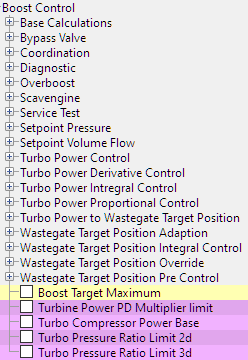
Boost Target Related Maps
- Turbo Pressure ratio limit 2d
- Turbo pressure ratio limit 3d*
- Boost target Max
- Boost Target Maximum*
- Basic Target Pressure Ratio
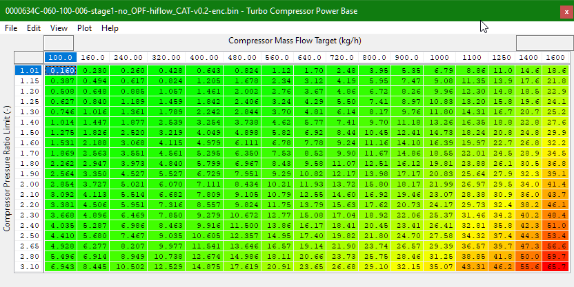
Compressor power maps:
- Turbo Compressor Power Base*
- Turbine Power PD Multiplier Limit
- Turbo Power Derivative Gain
- Turbo Power Derivative Gain Correction
- Turbo Power Derivative Dynamic Gain
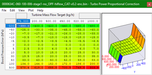
- Turbo Power Proportional Correction *
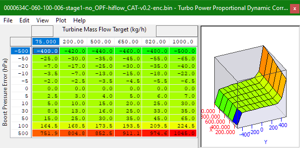
- Turbo Power Proportional Dynamic Correction
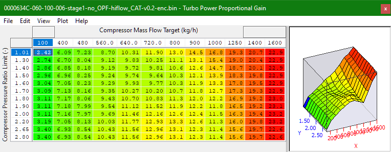
- Turbo Power Proportional Gain*
Turbine Maps
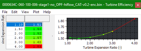
- Turbine Efficiency
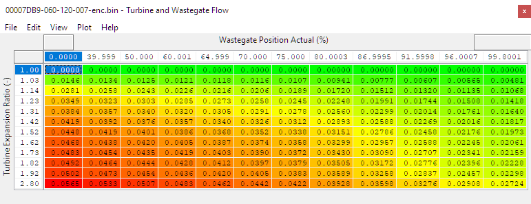
- Turbine Flow*
- Turbine and Wastegate Flow*
WG Position Maps
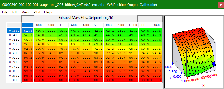
- WG Position Output Calibration*
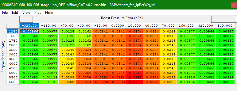
- BMWtchctr_fac_IpPctWg_M
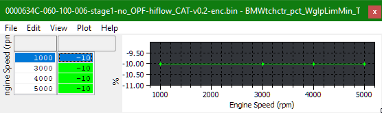
- BMWtchctr_pct_WgIpLimMin_T
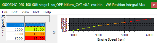
- WG Position Integral Max
*= Maps to adjust for greatest effect and driveability
Live Data Parameters
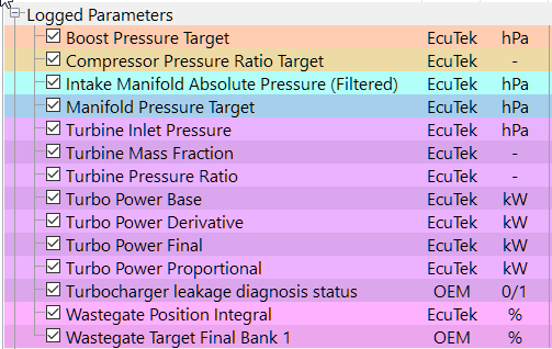
- Boost Pressure Pre Throttle - Boost pressure before the throttle (measured before the chargecooler)
- Boost Target - Target boost pressure (derived from the cylinder fill desired value)
- Boost Pressure Error - Difference between the Boost pressure and the target, (positive values are under target)
- Compressor Pressure Ratio Target - Target ratio
- Intake Manifold Absolute Pressure (Filtered) - Filtered and corrected manifold pressure (measured at the inlet port)
- Manifold Pressure Target -
- Turbine Inlet Pressure - Modelled pressure at entry of the turbocharger turbine housing
- Turbine Mass Fraction - Proportion of the total exhaust mass flow that flows exclusively through the turbine wheel
- Turbine Pressure Ratio - Ratio in pressure between the inlet and outlet of the exhaust housing (AKA Turbine Expansion Ratio)
- Turbo Power Base - Compressor shaft power required in kW (output of Compressor Power Base map)
- Turbo Power Proportional - Correction of the compressor shaft power in kW due to boost pressure error
- Turbo Power Derivative - Correction to the compressor shaft power in kW due to rate of change of the boost pressure
- Turbo Power Final - Final value of compressor shaft power used to calculate the base wastegate position
- Turbocharger Leakage Diagnosis Status - Turbo leakage detection is active (analysing for leak, does not indicate a failure)
- Wastegate Position Integral - Integral correction of the wastegate position in % (added to the calculated base position)
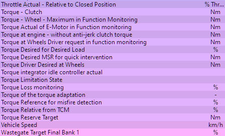
- Wastegate Target Final Bank 1 - Final target position of wastegate for the electronic actuator to try and achieve
Compressor Power
Once a boost target is calculated, the ECU uses this first value to calculate the mechanical power at the compressor wheel required to deliver the desired boost at the required airflow. Most of the boost control correction is also done in the same units, in this case all kW (kilowatts) before later being converted to an exhaust gas power and finally the wastegate position.
The BMW method uses raw compressor power, compared to say Volkwagen which uses a traditional map of compressor efficiency to calculate the required power. If a replacement turbo was to be tuned in theory it would be possible to generate some new base maps using the compressor map, but for most tuners, equally effective results can be had from logging and map refinement.
Turbo Compressor Power Base is the mechanical power in kW required at the turbine shaft to deliver the airflow (X axis) at the compressor pressure ratio (Y axis) the stock map is generally adequate for most tuning of the stock turbo, and even mildy upgraded turbos. If tuning a significantly modified turbo such as Pure800 or similar unit, then the main step is to ensure that both map axis cover the required airflow and pressure ratio. For reference a stock turbo is usually flat out at about 1380kg/h where a Pure800 will make more like 1800kg/h, and the stock X axis tops out at 1600kg/h.
A first step when correcting boost errors is to use the RaceROM logging and look at Turbine Power Final![]() vs Turbine Power Base and apply similar corrections to the base map. This is very effective when making smaller corrections, but some of the other maps mentioned later in this guide, especially the turbine flow maps and pressure loss maps should also be adjusted.
vs Turbine Power Base and apply similar corrections to the base map. This is very effective when making smaller corrections, but some of the other maps mentioned later in this guide, especially the turbine flow maps and pressure loss maps should also be adjusted.
Adding significantly too much to the table will result in negative corrections. As soon as all the corrections disappear the wastegate will close and cause an over-boost condition, which will be exacerbated when shifting. So make sure not to get too carried away using it as a volume knob when there are better better alternatives.
Compressor Power Correction maps
The base compressor power is corrected using a PID control loop, for Supra tuning only the Proportional and Derivative terms are used, and the correction amounts are controlled using maps. In general lowering the values in the gain map will reduce the proportional feedback of the system, which can be observed using the Turbine Power Proportional RaceROM logging parameter. If the base map is reasonably close this doesn't usually need much adjustment on a stock turbo, however significantly larger turbos often need the values significantly reducing to help prevent overshooting corrections and oscillating boost.
Compressor Power to Wastegate Position
Once a compressor power requirement is calculated it is used to calculate the correct wastegate position to deliver that shaft power using the turbine wheel and the available exhaust gas energy
Turbine Efficiency
This is actually the inverse of the efficiency, such that the compressor shaft power is multiplied by the output of this map to give the required turbine gas power that is ultimately regulated by the wastegate and actuator. Increasing the values in this map therefore increase the wastegate position values across the board. Without accurate data it's hard to calibrate this but larger turbochargers will maintain greater efficiency at high mass flows so the numbers can be reduced to give an overall effect on the whole boost control system.
Turbine Flow Maps are the efficiency of the turbo to calculate based on the mass flow and pressure across the turbine. How much power it could have if it used all of the available exhaust gas to turn the turbo, how much does it actually need (say you're generating 150kw of exhaust energy and you only need 60 for the desired boost. You'll use about 40% of the exhaust energy to drive the turbine. From there it feeds back in to the wg position output to figure out the fraction of the exhaust power used. Many of the tables only go to 1250 kg/h but for more modified cars those levels will need to get bumped up when you start exceeding the values of the axis. Bigger power cars may be closer to 1800 kg/h
For B58 engines turbine shaft power is in KW, B48 everything is in turbine power. The shaft power number is what is adjusted instead so beginner boost control is going to be utilizing the compressor power map as that is the closest thing to a base wastegate map. Turbo power proportional control gain etc. is the PID control to change the output.
Turbine Flow
Sets the flow characteristics for the gas flowing only through the turbine wheel of the turbo. The most important thing to ensure is that the input axis covers the range of expected values for the turbine expansion ratio (aka Turbine Pressure Ratio)
Turbine and Wastegate Flow
Sets the combined exhaust flow for both the turbine and the wastegate based on the wastegate's position. As you would expect, at 100% wastegate position the values should mimic the Turbine Flow map above. Will need to be rescaled if you change the turbocharger or exhaust housing.
Combined flow coefficient. Last column for 100% wg position should match the turbine flow map. Scaling this map up can be useful for turbos with larger turbines, but it should also have enough headroom for high turbine PRs attempting high boost
Mass Flow Fraction and Wastegate Position
Wastegate Position Integral Correction Gain
(BMWtchctr_fac_lapPctWg_M)
Wastegate Position Integral Maximum Limit
Wastegate Position Integral Minimum Limit
(BMWTchctr_pct_WglpLimMin_T)
Exhaust System Pressure Model
Keeping in mind that the system has many models that need to be in harmony, we can take a look at common things that will happen with the Exhaust system.
The stock computer compensates for pressure loss across the catalyst, exhaust pressure vs turbine outlet pressure, and keeps an idea of the soot loading that happens to the Particulate filter in order to add to the pressure loss. If you were to swap the stock components out for a high flow catalyst and filter combo, you'll start to overboost. This is because the system is still compensating for the exhaust restriction when calculating for the turbo flow. In that instance rather than adjusting a turbo map to have the computer adjust wastegate position, you'll want to tune the pressure drop appropriately for the catalyst and particulate filter used.
Once you have the models set up, the boost pressure should be fairly under control for the modifications.
Exhaust Pressure Drop - Catalyst
Sets the change in exhaust pressure as caused by the catalyst. If you swap it to a higher flowing aftermarket catalyst you'll need to reduce these values in response.
Exhaust Pressure Drop - Particulate Filter
Adjusts for shifts in exhaust pressure based on soot loading of the particulate filter. In regions where the vehicle isn't equipped with a particulate filter this table is set to zero.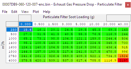
Exhaust Gas Pressure Drop - System Flap Open/Closed
Sets the expected amount of change in exhaust pressure (and thus boost error) caused by the exhaust valve being in an open or closed position. If changing to an aftermarket exhaust these tables will need to be tweaked accordingly.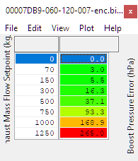
Throttle Closures
Typically you'll see throttle closures that are representative of excessive load or over-boosting. You'll typically see boost pressures rise slightly as the throttle closes from the increased pressure against the throttle. It usually uses valve lift to control cylinder filling however if you go over a certain threshold of over-boosting it will switch to a throttle based control to reduce that. Even a mild torque demand increase on a stock car can cause throttle closures, and while these throttle closures aren't typically perceptible in the car, cleaning it up is the best practice and should result in a better tune. While not ideal, increasing maximum torque and load limits in order to demand an unattainable amount of load can prevent throttle closing.
Boost Control Terms
Compressor Pressure Ratio is not boost it's the ratio of pressure from the compressor inlet to outlet. The value is based on ambient pressure. If you want 1bar gauge pressure (2bar absolute) at altitude but pressure ratio would be different due to the change in atmospheric pressure. If you want to use this way to change boost pressure you'll want to adjust for ambient pressure and handle the limiter on the pressure ratio accordingly.
Turbine Pressure Ratio (AKA Turbine Expansion Ratio) is the difference in the pressure before and after the turbocharger. If you upgrade to a larger turbo you'll almost certainly have a different level of backpressure than shown in the factory maps. A good starting place is to look at how much bigger the turbo wheel is, and scale the range by that amount for both the turbine and wastegate flow. If those values aren't scaled correctly, you'll find that the ECU thinks airflow is much worse than it really is. This results in the vehicle using too much wastegate duty for the car to make the pressure that it thinks it needs. Keeping these maps under control can take a lot of headaches out of the boost control system.
Exhaust
RaceROM Burble Control
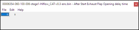
After Start Exhaust Flap Opening Delay Time
Sets the amount of time (In Seconds) the computer will require to pass before allowing the exhaust flap to open after initial startup.
Exhaust Flap Load Threshold
There are various maps that control the exhaust flap position based on the vehicle's load and RPM. The table being referenced will change based on a few factors
- Status of the Roof (Open or closed)
- Transmission type the vehicle is equipped with
- Drive mode selected (Sport, Normal)
Looks like the values you'll input are either -50 or 150?
Exhaust Flap Minimum Vehicle Speed
Sets a minimum vehicle speed for the computer to begin actively manipulating the exhaust flap based on the Exhaust Flap Load Threshold map
Map List
- After Start Exhaust Flap Opening Delay Time
- Exhaust Flap Minimum Vehicle Speed
- Exhaust Flap Load Threshold (MT/AT/DKG) (Open/Closed Roof) (Sport, Normal)
EcuTek ProECU tuning tools tools should only be used by experienced tuners who understand the product and engine calibration.
If you do not fully understand this product then you WILL damage your engine, ECU or your vehicle.
Please ensure you fully read all EcuTek manuals BEFORE attempting to use ProECU with your laptop or your vehicle.
Use with extreme caution and understanding at all times, if in doubt then do not proceed.
EcuTek accepts no responsibility for any damage to the engine, ECU or any part of the vehicle that results directly or indirectly from using the product.
** If you are in any doubt that you do NOT have the experienced required to use this product then you should NOT USE IT **
Retail customers
** If you have any doubt that you do NOT have the experienced required to use this product then you should NOT USE IT, you should simply contact your EcuTek Master Tuner shown clearly on the top of your Programming Kit or visit your preferred tuning shop to have a professional tuner to use it for you **