BRZ/FRS/GT86 RaceROM Boost Control & Forced Induction
![]()
BRZ/FRS/GT86 RaceROM Tuning Guide Suplement: Forced Induction and Boost Control
How to tune a Forced Induction setup
The factory ECU has not been calibrated for Forced Induction (FI) installations, so after fitting either a Turbocharger (TC) or Supercharger (SC), the key maps will need adjusting. With more airflow and higher engine load, the Ignition and fuel map load axis will need rescaling to provide the resolution required for safe calibration. The Injection maps will also need adjusting.
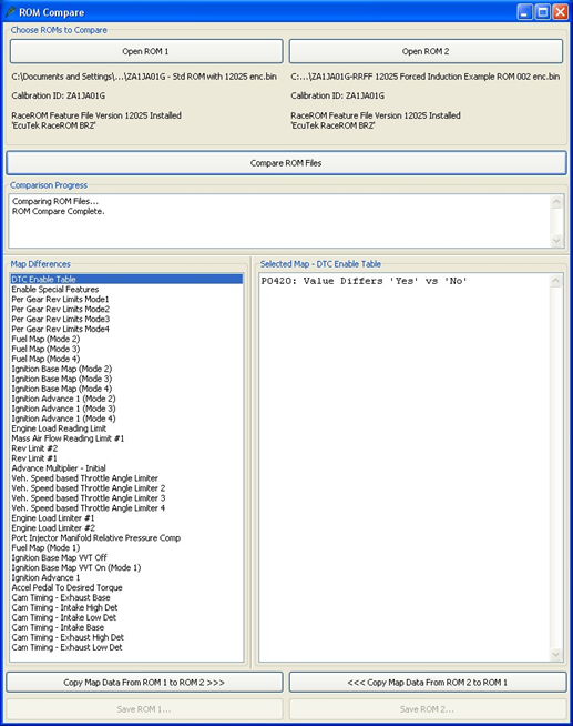
It is suggested that any FI tune should start with our base FI Example ROM file, these are available for the following region ROMs: USA, Euro or JDM region. These ROMs have the key maps modified to start your calibration with. If your ROM is for another region, use ROM COMPARE*** to see the maps that have been altered and the typical settings used.
Here are the changes we have made and the reasons why we made these changes:
Engine Load Map Rescaling
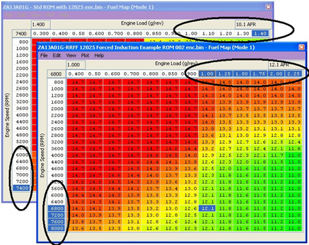
Fuel Maps – we rescaled the X axis from 1.4 to 2.25 Engine Load as shown below, you can also see the optimised AFR values compared with a stock fuel map.
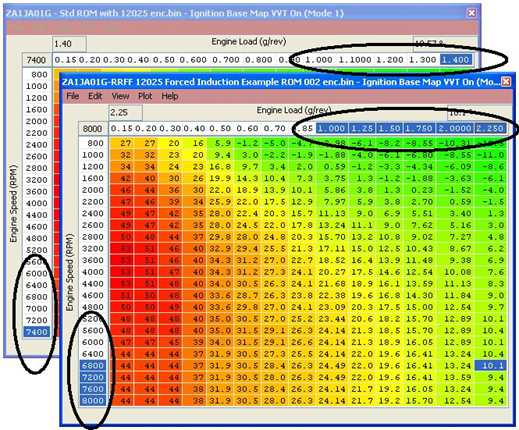
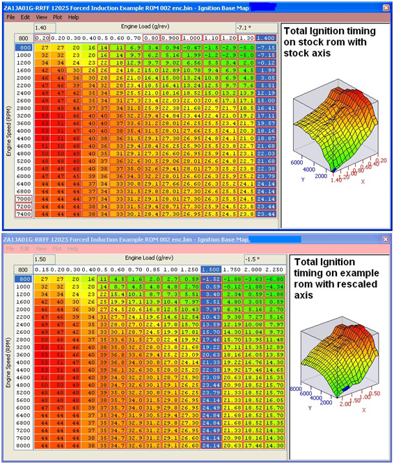
Ignition Base Maps – we rescaled the X axis from 1.4 to 2.25 Engine Load as shown below, we also advanced the Ignition timing slightly over stock settings.
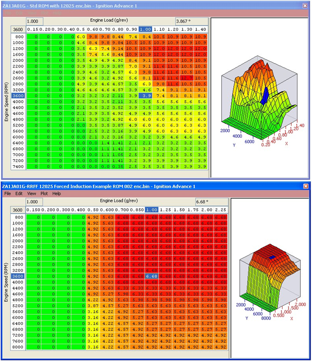
Ignition Advance maps - we rescaled the X axis from 1.4 to 2.25 Engine Load, and have also smoothed the advance map values for easier calculations of Ignition timing when added to the Ignition Base map. This smoothing method also helps to visualise fine learning knock retard by looking at ‘knock control learned value’ in LIVE DATA. With 6 degrees in the advance map, the
‘knock control learned value’ should show a consistent 5 or 6 degrees during logging
(assuming there is no learned knock retard in memory for fine learning and also assuming the Advance Multiplier is 1).
It is possible to calculate the complete Ignition timing by adding the Ignition Base map to the Ignition Advance map, this can be done in Excel but ensure that your X and Y axis line up when you add the values together.
We have added the stock Ignition Base map to the stock Ignition Advance map to see the total Ignition timing for a stock car.
We have also done the same for the example ROM and the differences can be seen below, note th stock total ignition timing screen shot is only scaled to 1.4 Engine Load compared to the example ROM that’s scaled to 2.25 Engine Load.
You can see the example ROM has a smoother profile vs the stock map.
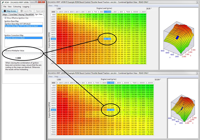
Using the combined Ignition view makes it much easier to see the total Ignition timing.
By simply moving the slider from left to right we can see the effect the Advance Multiplier has on the total Ignition Timing.
If the AM is 0 then NONE of the Ignition Advance map will be added to the Ignition Base map.
If the AM is 1 then ALL of the Ignition Advance map will be added to the Ignition Base map. If the AM is 0.73 then 73% of the current Ignition Advance map value will be added to the Ignition Base map.
See the “Advance Multiplier - Coarse Correction” section in the Ignition Timing section for more information.
Forced Induction Ignition
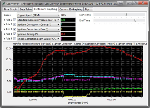
Tuners will note that Ignition timing will normally climb (advance) on a NA car at higher RPM. But with a Vortech supercharger installed the Ignition timing is retarding at higher RPM (past 5500rpm), this is due to the characteristic of the centrifugal supercharger which creates more boost the faster you spin it. See the RED line decreasing as the boost increases and increases.
Forced Induction Fueling
The stock fuel system can deliver around 300bhp on stock Port and Direct Injection injectors. To achieve the full fuel delivery required for 300bhp on stock injection you need to ensure that the Port Injectors (PI) are running at 80-90% at 7000rpm on.
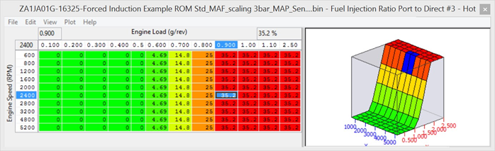
This PI/DI ratio is controlled by the 3d maps called ‘Fuel Injection Ratio Port to Direct #1 - #3’.
The factory map is configured so the PI will deliver 20% of the required fuel volume amount past 5200rpm. We need to increase this PI ratio to around 35% so the PI Duty is over 80% like shown below.
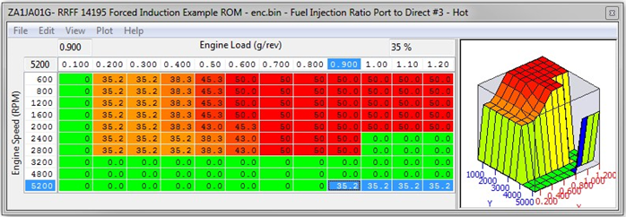
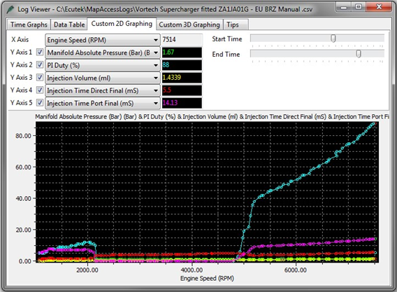
With PI delivering 35% of the fuel volume the PI Duty is now running at 88% as seen below, this reduces the DI open time period giving more potential DI open time if we need it.
In the log file below showing our (Vortech Supercharge GT86) you can see the DI is only open for 5.5ms and a total fuel volume of 1.43ml.
This is getting near the limit of the stock fueling and the maximum open time for the DI injectors.
This also applies when larger PI have been fitted but we make a further change as well.
Larger Port Injector Tuning
When larger PI injectors have been fitted (450cc, 750cc or 1000cc) it can cause a slight hesitation at low RPM and light load, this can happen as the Port Injectors switch from off to the factory calibration ratio of 35% fuel volume delivery. This can be changed using the PI ratio Threshold – Lower limit but the best solution is to prevent the PI from working at low RPM and light load.
See the following screenshot example of how to configure all 3 of the ‘Port to Direct Injection Ratio’ maps. The PI will not work until there is a reasonable load and airflow and this will eliminate any transition drivability issues.
If you wish the PI to deliver less than 35% of the total fuel volume amount then reduce the 1d map called ‘PI Ratio Threshold – Lower Limit’ down from 35% for this to be possible.
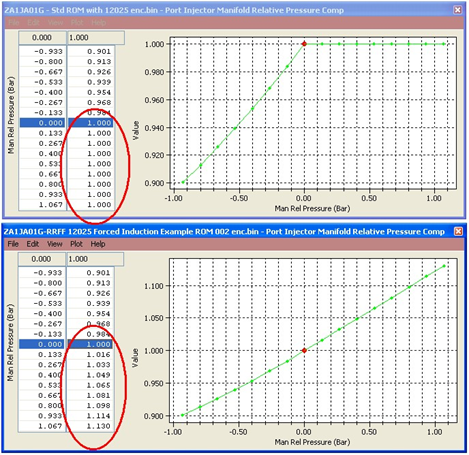
- Port Injector Manifold Relative Pressure Compensation – rescaled for positive pressure compensation so that the correct volume of Port Injector fuel will be delivered relative to forced induction manifold pressure.
- DI Quantity Maximum Allowed – !!! Very Important to raise this map !!! These DI Limiter values should be increased to 1.1 to 1.3 ml otherwise the DI will not be allowed to inject the fuel volume that is required. Try to you keep your DI open time below 5.5ms past 5000rpm to avoid the DI Injecting when the spark plug is fired. Make sure you check the logging parameter called Fuel Injection End DI to Spark (ms) which shows the time period left between the direct injector closing and the spark plug firing, critical to maximize the DI Open Time.
Fuel Injection Ratio Port to Direct #1- #3 – These maps define the distribution ratio between PI and DI for a given volume of fuel. This can be altered to allow PI to be used full time (not recommended as the DI needs fuel flowing through the injector to stay cool) or at a given percentage, if a larger injector is required to supply between 0 to 35% or from 75% to 100% of the total fuel quantity adjust the PI ratio thresholds to suit your requirements. If you wish the PI ratio to always follow the Fuel injection ratio Port to Direct maps set the load or RPM threshold to a low value.‘
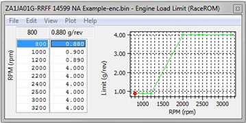
- Engine Load Limit (RaceROM) – This map MUST be increased or the AFR will be lean on full load, the stock load limit values are retained at lower RPM to prevent a unnaturally high Engine Load being achieved which causes poor running on full load and full throttle. Keep the values low below 1600rpm to avoid an unrealistic engine load reading at low rpm which will cause a rich AFR and retarded ignition due to valve overlap, see below.
- Engine Load Reading Limit – Increased to avoid the engine load being capped and making the fuel mixture too lean.
- Engine Load Limiters #1 #2 – These are replaced by the Engine Load Limit (RaceROM) map.
- Mass Air Flow reading Limit – Increased to avoid the engine load being capped and making the fuel mixture too lean.
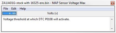
- MAF Sensor Voltage Failsafe – When the MAF sensor Voltage output reach its maximum threshold the ECU will then use the Manifold Absolute Pressure (MAP) Sensor for its Engine Load calculation, you will also get a P0103 DTC.
If using the “stock” MAP sensor these values will be unsuitable for forced induction vehicles as the ignition timing will be too far advanced and the fuelling too lean, this is due to the stock MAP sensor being unable to accurately measure positive manifold pressure conditions, potentially this could cause engine damage.
To avoid this condition we must change the MAF Failsafe Load Calculation Multiplier and the MAP Sensor Voltage Max value.
Below are the Stock values:
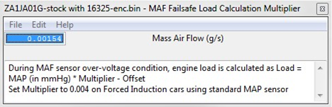
So Load = 0.00154 * MAP (in mmHg) – 0.16, now 1.0Bar is equivalent to 760 mmHg.
So assuming a standard MAP Sensor is fitted and vehicle is making 1 bar boost at 7000rpm (2bar Absolute) then you hit 5volts on the MAF and ECU goes fail safe and uses the MAP sensor reading for its load calculation. This is the calculation that will happen.
1.37 * 760 = 988, now 988 * 0.00154 = 1.52 Engine Load
Next SUBTRACT the Offset value of 0.16 = 1.36 Engine Load
So the new Engine Load is 1.36 when the MAF hits 5 volts with STD MAP sensor. Now the true engine load should be 2.5+ so this means over advanced Ignition timing and lean fueling so this is why this map is important on FI cars running stock map sensor.
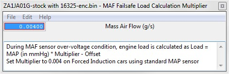
Suggested values:
So when running a stock MAP sensor on a FI vehicle we suggest to change the Multiplier to 0.004 as shown below:
So 1.37 * 760 (Bar into mmHg) = 988, now 988 * 0.004 = 3.952, next SUBTRACT the Offset value of 0.16 = 3.79 Engine Load which is over rich and retarded should you hit 5v MAF output! Now with a 3 bar MAP sensor you should still change the value as shown below.
Assuming you are making 2bar absolute when you hit 5 volts MAF
So 2 * 760 (Bar into mmHg) = 1520, now 1520 * 0.00154 = 2.3408, next SUBTRACT the Offset value of 0.16 = Engine Load 2.18 for a 3bar MAP sensor running 2bar boost when they hit 5volts MAF.
If you change the MAF Failsafe Load Calculation Multiplier to 0.002 then if you hit 5 volts MAF at 2 bar absolute boost then the Engine Load will be 2.88.
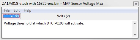
We also suggest to raise the DTC threshold as below.
- Cam Timing – Intake and Exhaust - have been optimised to provide a greater torque output and a more consistent AFR reading across the midrange, the low rpm, low load region has also been reduced therefore reducing internal EGR affect used for emission control. The X axis has been rescaled for a higher engine load.
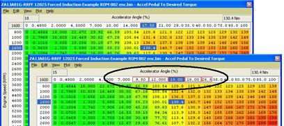
- Accel Pedal to Desired Torque – The X axis values have been slightly reduced which elegantly provides a greater torque output for a lesser accel pedal amount.
- Advance Multiplier Initial – we increased the value to 1 so that 100% of the Ignition Advance is added to the Ignition Base map immediately after programming the ECU so there is waiting for the AM to increase from 0.7 to 1 each time, saving valuable time!
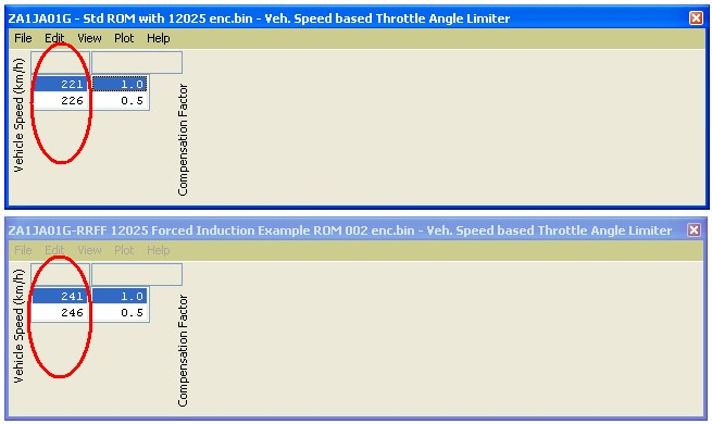
- Vehicle Speed Based Throttle Limiter – The vehicle speed has been increased by in the left hand column, do not adjust the right hand column values as this can cause trustful throttle CEL conditions.
- DTC Enable – DTC's may need adjustment if utilizing an external EBCS into an existing ECU sensor input.
- Enable Special Features – we turned on Launch Control, Flat Foot Shift and Auto Blip for fun.
- Rev Limits – we raised the rev limits by 200rpm to 7600rpm.
- Ensure you are using the latest RRFF version 20479 or newer which has improved fueling calculations to prevent lean running at high RPM.
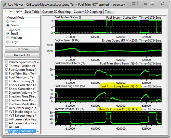
How to turn off Long Term Fuel Trims
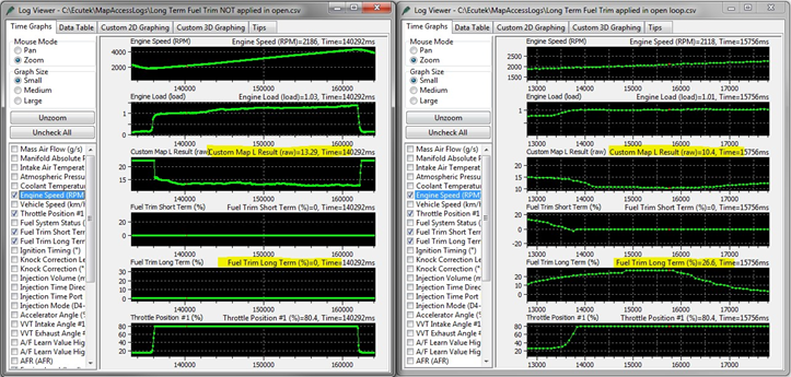
As part of the closed loop fuelling control, the Long Term Fuel trim can be applied in open loop. This can cause the AFR to change significantly. See the log file below on the left hand side where on full load the LTFT were zero and the AFR is 13.29 (Custom Map L Result is the Innovate Wideband import).
On the right hand log you can see the LTFT is +26% and the AFR is now 10.4AFR!
If the LTFT was -26% this would make the AFR very lean and on a forced induction vehicle this could cause engine damage so we need to limit the LTFT from working.
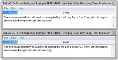
These are the minimum and maximum allowed fuel trims applied in open loop. Set these values to zero to prevent hte closed loop trims from working and being applied in open loop. You can see below that each time stft stops working and the ecu is in open lop (Fuel system status 4) then the LTFT are set at 0
Using the Rear O2 Sensor input
If you are using the Rear O2 sensor input pin it is essential to turn off the ECU Long Term Fuel Trims and AF Correction #3 as well.
See the “How to turn off Long Term Fuel Trims” and “How to disable Rear O2 AF Correction #3” headings for more information on how to do this.
How to disable Rear O2 AF Correction #3
When removing or repurposing the Rear O2 sensor the AF Correction #3 can become active and will change the Target AFR during closed loop, the logging parameter called Equivalence Ratio Commanded shows this particularly well.
To avoid AF Correction #3 altering the cruise closed loop Target AFR you need to set the values in the following two maps to zero:
- AF Correction #3 Limit – Rear O2
- AF Correction #3 CL Target Compensation Limits
Using the CPC Pressure sensor input
If you repurpose the CPC Pressure Sensor input on a USDM vehicle then the Atmospheric Pressure calculation will be incorrect. We have added a checkbox on affected vehicles to force the ECU to use the MAP sensor for the Atmospheric Pressure Calculation instead. Please enable this feature when repurposing the CPC Pressure Sensor on a USDM vehicle so the atmospheric pressure reading is correct and shown correctly in Live Data.
CPC Control
Canister purge control solenoid valve target airflow map, no need to adjust.
If the CPC valve has been replaced with wastegate solenoid valve then use Custom Maps for boost control.
CPC Duty
Canister purge control solenoid valve duty map, no need to adjust this map.
If the CPC valve has been replaced with wastegate solenoid valve then use Custom Maps for boost control.
CPC Duty Multiplier
The operating frequency of the CPC solenoid valve.
On turbo BRZ/FR-S/GT86 models where the CPC valve is replaced with a fast switching wastegate duty solenoid valve then we suggest you set the frequency value to either 20% to 30%, some tuners report using 35 to 45% but we feel this is too high. This will vary depending on the type of valve used.
EcuTek ProECU tuning tools tools should only be used by experienced tuners who understand the product and engine calibration.
If you do not fully understand this product then you WILL damage your engine, ECU or your vehicle.
Please ensure you fully read all EcuTek manuals BEFORE attempting to use ProECU with your laptop or your vehicle.
Use with extreme caution and understanding at all times, if in doubt then do not proceed.
EcuTek accepts no responsibility for any damage to the engine, ECU or any part of the vehicle that results directly or indirectly from using the product.
** If you are in any doubt that you do NOT have the experience required to use this product then you should NOT USE IT **
Retail customers
** If you have any doubt that you do NOT have the experience required to use this product then you should NOT USE IT, you should simply contact your EcuTek Master Tuner shown clearly on the top of your Programming Kit or visit your preferred tuning shop to have a professional tuner use it for you **