BRZ/FRS/GT86 RaceROM Tuning Guide (up to v12.3)
- Brandyn Mowat
- Paul Blamire
- Michael Howard
![]()
RaceRom Tuning Guide
Accelerator Trim
The Accelerator trim map allows you to adjust the accelerator response by intercepting the accelerator position signal and replacing it with a different value. This can improve drivability in vehicles that do not respond to pedal input in a linear fashion.

Auto Blip Feature
Manual Transmission Vehicles Only
The Auto Blip feature applies a short burst of throttle when the driver is down-shifting under braking. This raises the RPM to keep the engine operating within its power band and provides a smooth entry into the lower gear by reducing engine braking.
AutoBlip Minimum Speed
Vehicle speed that must be exceeded for AutoBlip to be enabled.
AutoBlip Pedal Percentage
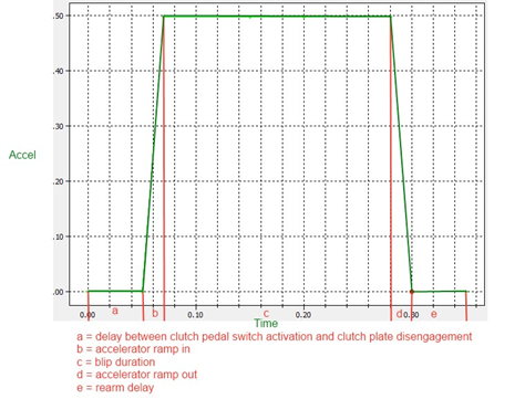
The x axis is time since Autoblip was triggered (described below). Autoblip ends when the maximum time on the X axis is exceeded. Be careful to avoid using too much Accel at low RPM as this will cause the car to push on aggressively.
How to Use Auto Throttle Blip
The Auto Blip feature is activated when all of the following conditions are met:
- The ‘Auto Blip Enable checkbox’ is ON for the current Map Switch Mode
- The vehicle is travelling faster than the Auto Blip Minimum Speed
- The driver presses the brake pedal, followed by the clutch pedal
I'ts important to push the clutch pedal all the way down relatively quickly, going slowly or only part way can cause the blip to occur when the clutch is still partially engaged causing a lurching motion or potential damage.
The accelerator blip is immediately cancelled when one of the following conditions occurs:
- The driver releases the Brake Pedal
- The driver releases the Clutch Pedal
- The vehicle speed falls below the ‘Auto Blip Minimum Speed’ The Auto Blip timer reaches the end of the map
When the driver down-shifts while braking, the ECU will blip the accelerator. The amount of accelerator to apply and the duration of the blip is controlled by the ‘AutoBlip Pedal Percentage Map’ as shown in the diagram below, this is a 2D slice through the 3D map.
Boost Control
The EcuTek BRZ boost control is based on the proven strategy used in GT-R RaceROM Phase 6. We recommend tuners use RaceROM boost control as it now has its own full set of dedicated maps so you no longer have to create a large number of custom maps. Upon adding a version 10 or later RRFF, this option is enabled by a simple check box, and comes pre-populated with some sensible values that should allow good control after a little tuning. Boost control uses Manifold Absolute Pressure throughout. Please ensure you are familiar with the concept of the absolute pressure before tuning the boost control. Remember that a target of 1.0 is close to sea-level atmospheric pressure and not positive boost.Absolute Boost
For more information check out the BRZ/FRS/GT86 RaceROM Tuning Guide Supplement: Boost Control & Forced Induction
Custom Maps
We have improved our unique and innovative Custom Maps feature to enable even more tuning possibilities. With the addition of our dedicated boost control and FlexFuel strategies, all 16 custom maps are now available for the tuners to further exploit the power of RaceROM.
Additional inputs and outputs, combined with expanded possibilities for manipulating the values, allow for complex control strategies to be created from something as simple as a fuel pressure fail safe to a slip target based multilayered traction control system.
This feature is so versatile it was previously used for things like traction control, flex fuel, and even advanced boost control. While no longer needed for those functions, you can still use these custom maps to do all sorts of additional tasks.
The map utilizes specific user-defined x and y-axis, output channel, and allows you to set custom scenarios for when the table should be active. This means you can set up dozens of different systems that utilize everything from factory tables and sensors, to custom parameters from hijacked sensor inputs.
For more information on custom map tuning check out our guide RaceROM Custom Maps Tuning Guide
Flat Foot Shifting Feature (MT Models Only
How To Use Flat Foot Shifting
- ‘The Flat Foot Shift Enable’ checkbox is ON for the current Map Switch Mode
- The vehicle is travelling faster than the ‘Flat Foot Shift Minimum Speed’
- The accelerator amount is greater than the value in the ‘Full Accelerator Threshold Map’
- The driver is pressing the Clutch pedal
As the Flat Foot Shifting feature activates, a temporary rev limit is set that is slightly higher than the current RPM. The ignition timing is retarded by a specified amount that reduces engine torque while preventing the RPM from rising too rapidly. When the driver completes the gear change, the temporary rev limit and timing adjustment are removed.
The Flat Foot Shifting Feature is cancelled when one of the following conditions occurs:
- The driver releases the Clutch pedal
- The driver lifts off the accelerator
- The vehicle speed falls below the value in the ‘Flat Foot Shift Minimum Speed Map’
An AFR adjustment is provided that allows you to enrichen the mixture during the shift. The richer AFR cannot be measured from the exhaust gas due to the operation of the rev limiter.
Flex Fuel
The BRZ/FRS/GT86 platform have proven to be a platform that takes to flex fuel fairly well, making additional power even without forced induction. While some of the early generation high pressure fuel pumps would begin chirping with or without ethanol, all of them have proven to be compatible with ethanol.
For a complete rundown of the RaceROM Flex Fuel system check out our guide here
Flex Fuel Ethanol Sensor Installation
In order to set up Flex Fuel properly you'll first need to purchase and setup an ethanol content sensor kit. These kits typically include a sensor, module, and potentially replacement fuel lines depending on where it is installed.
After installation you'll need to setup the sensor in the Sensors section of the map list.
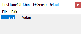
FF Sensor Default
Sets an ethanol value the system will revert to in the event that the output goes outside the normal bounds of the voltage (FF Sensor Max & Min). You'll typically want to set it close to what the end user is typically going to have in the vehicle. You'll want to set the value close to the voltage output of e85 if running e85 all the time, close to e10 if they typically run pump gas, or a safe middle value if they go back and forth frequently.
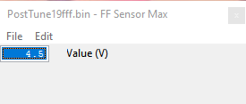
FF Sensor Max
Maximum sensor voltage for the sensor. You'll want to set this to the high end of your kits voltage range which can vary. Common kits use either 4.5v or 5v for the high end, refer to the manufacturer for their recommended values.
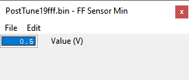
FF Sensor Min
Minimum sensor voltage for the sensor. You'll want to set this to the low end of your kits voltage range which can vary. Common kits use either 0.5v or 0v for the high end, refer to the manufacturer for their recommended values.
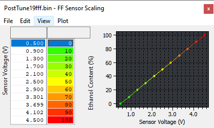
FF Sensor Scaling
This is where you setup the relationship between the voltage of your sensor and the ethanol content it designates. Most kits output a higher ethanol content the higher the voltage level, refer to your manufacturer for their recommended values.
FF Sensor Smoothing
Applies a smoothing value to your ethanol content values being used by the computer for calculations. Can be helpful to get a more consistent value if the signal you get from your sensor tends to have small spikes.
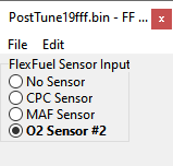
FF Sensor Source
Selects what input is being used to add ethanol content to the vehicle. Keep in mind that this will also require deleting whatever sensor was previously on that channel, so check local laws for legality and make sure to adjust the tune correctly to prevent any issues.
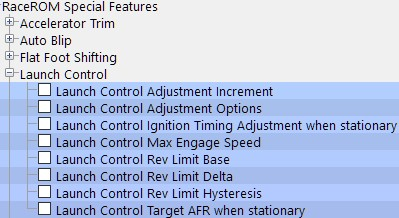
Launch Control
The Launch Control feature limits maximum RPM during launch to help control wheel spin and allow the fastest possible take off.
How to Activate Launch Control
- Ensure the ‘Launch Control Enable’ checkbox is ON for the current Map Switch Mode
- Engine must be running and Vehicle must be stationary
- Press clutch pedal and move the gear stick to 1st position
- Quickly press the accelerator all the way to the floor
- Adjust launch RPM using the cruise control stalk
- Release the clutch to commence launch
When Launch Control is active, the rev limit will be set to the ‘Launch Control Rev Limit’. This limit defaults to the
'Launch Control Rev Limit Base" value and can be adjusted up and down using the cruise control stalk. Select "Res/Acc" to increase the launch RPM and "Set/Cst" to decrease it. An alternative method of adjustment is available for vehicles without cruise control.
During the launch, the rev limit increases according to the 'Launch Control Rev Limit Delta, This 2D map, indexed by elapsed time, has multiple columns to allow you to set up a multi-stage system for best results.
Adjustments are provided that allow you to richen the AFR and retard the timing when the vehicle is stationary in order to create pops and bangs. This adjustment is removed as soon as the vehicle starts to move.
The Launch Control feature is deactivated when one of the following conditions occurs:
- The elapsed time exceeds the last column on the ‘Launch Control Rev Limit Delta Map’
- The driver lifts off the accelerator
- The driver performs a flatfoot shift
How To Adjust Launch RPM Limit
Vehicles without cruise control
Set the launch control rev limit as follows:
- Ensure the ‘Launch Control Enable’ checkbox is ON for the current Map Switch Mode
- Engine must be running and Vehicle must be stationary
- Turn on rear window demist switch
- Press clutch
- Rev engine and hold at desired launch RPM
- Turn off rear window demist switch
- Check engine light will flash to indicate that new limit has been saved.
Vehicles with automatic transmission
(Due to the operation of the automatic transmission, we do not advise you use the Launch Control feature) Activate the launch control as follows:
- Ensure the ‘Launch Control Enable’ checkbox is ON for the current Map Switch Mode
- Engine must be running and Vehicle must be stationary
- Press brake pedal and move the gear stick to a forward drive position
- Quickly press the accelerator all the way to the floor
- Adjust launch RPM using the cruise control stalk
- Release the brake to commence launch
Ensure that the launch RPM is below the stall speed of the torque converter.
Map List
Live Data Parameters
- Launch RPM – Launch control RPM setpoint
- Launch RPM Error – Difference between current RPM and the Target, positive is over target
- LFA State – Diagnostic status info for LC, FFS and AutoBlip, for use by EcuTek support
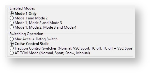
Map Switching
Method of Operation
The Map Switching feature is enabled by the option buttons in the ‘Map Switch Options' map. Four modes are allowed by default, but this can be reduced if desired. In “Mode 1”, the ECU will use the original ECU maps for Fuelling, Base Ignition Timing and Ignition Advance. In the other three modes, the ECU will use the new Fuel, and Ignition Timing maps labelled Mode2, Mode3 and Mode4 as appropriate.
Currently, the ECU does not always remain in the chosen mode when the ignition is turned off. We hope to develop a solution to this problem. In the interim, you should always check the current mode when starting the vehicle.
Switching mode using the cruise control stalk
- Ignition must be ON
- Ensure cruise control master switch is OFF
- Pull the cruise lever towards you (i.e. cancel position) and hold for 1 second.
- The tachometer will move to 1000, 2000, 3000 or 4000 rpm to indicate the currently active mode.
- Move the cruise lever up (res/acc position) to increase the mode.
- Move the cruise lever down (set/cst position) to decrease the mode.
- Save the selected mode by pulling the cruise lever towards you (cancel position) or waiting 3 seconds.
Switching mode using the accelerator and defog switch
The driver can switch modes by turning on the rear window demist switch while holding the accelerator to the floor. Every time you do this, the mode increases by 1. After mode 4, it goes back to mode 1.
The check engine light will flash to indicate which mode has been set: One flash for mode 1, two flashes for mode 2, three flashes for mode 3, etc.
Switching mode using the traction and stability control switches
When this option is selected, the ECU maps are selected depending on the vehicle's traction and stability settings.
- Mode 1 - Traction Control on, VSC Normal
- Mode 2 - Traction Control on, VSC Sport
- Mode 3 - Traction Control off, VSC Normal
- Mode 4 - Traction Control off, VSC Sport
Switching mode using the Automatic Transmission Mode
When this option is selected, the ECU maps are selected depending on the Automatic Transmission setting.
- Mode 1 - Normal
- Mode 2 - Sport
- Mode 3 - Snow
- Mode 4 - Manual
Integration with Launch Control, Flat Foot Shifting and Auto Blip
The Launch Control, Flat Foot Shifting and Auto Blip features can be independently enabled in each of the four modes.
Logging
The “Mapswitch Mode” diagnostic parameter can be used to log the current map switch mode.
Speed Density
EcuTek RaceROM Feature Files (RRFF) offer a Speed Density tuning option for trade customers, or Retail customers that have purchased the optional RaceROM BRZ upgrade package. This is a MAP sensor based load input into the ECU (compared to the more forgiving factory MAF sensor based load input). In certain situations Speed Density is more suitable over a MAF based input, these are usually: In these situations the Speed Density or Hybrid Speed Density can be used.
For more information check out our complete guide BRZ/FRS/GT86 RaceROM Speed Density Setup
EcuTek ProECU tuning tools tools should only be used by experienced tuners who understand the product and engine calibration.
If you do not fully understand this product then you WILL damage your engine, ECU or your vehicle.
Please ensure you fully read all EcuTek manuals BEFORE attempting to use ProECU with your laptop or your vehicle.
Use with extreme caution and understanding at all times, if in doubt then do not proceed.
EcuTek accepts no responsibility for any damage to the engine, ECU or any part of the vehicle that results directly or indirectly from using the product.
** If you are in any doubt that you do NOT have the experience required to use this product then you should NOT USE IT **
Retail customers
** If you have any doubt that you do NOT have the experience required to use this product then you should NOT USE IT, you should simply contact your EcuTek Master Tuner shown clearly on the top of your Programming Kit or visit your preferred tuning shop to have a professional tuner use it for you **
Boost Control
Flex Fuel integration for target and limit
Separate high/low altitude wastegate base duty maps
Overall enable RPM below which the wastegate solenoid is disabled
Boost control activation based on VVT status
Safety limits for boost target
WG base duty multiplier for gear/IAT
Throttle based boost limit per mapswitch Mode
Custom sensor input definition
PI Fuel pressure sensor
Coolant pressure sensor
Flex Fuel sensor (Ethanol Content)
Wideband O2 Sensor
Define Min and Max voltages to detect failed sensor
Set default value for failed sensors
Adjustable sensor filtering
Closed Loop Full Load Fuel Control
Closed Loop control
Enable per Map Switch mode
Easy to tune!
Flex Fuel
Optionally define a pre-determined ethanol content override per map switch mode
Sensor smoothing
Sensor output freezing to combat fluctuations caused by aerated fuel
Ignition offset map
Fuel multiplier map
AFR target offset map
Separate live data values for actual sensor output (which may vary with inadequate fuel systems) and the ethanol content carried forward into the Flex Fuel strategy (which may be fixed due to load thresholds per Map switch mode).
Custom Maps
Added additional inputs
AFR - Actual
AFR - Target
AFR - Wideband
Boost Target
Clutch Pedal
Coolant Pressure
Fuel Pressure
Ethanol Content
Gear shift sensor
Ignition timing final
Injector open time DI
Injector open time PI
Knock correction
Lateral G
Launch RPM
Launch RPM Error
Wheel slip
Added new outputs
Boost target
Torque actual
SD volumetric efficiency
Added axis selection criteria function for easy safeguards
Added separate deactivation timer
Speed Density
Added Atmospheric Pressure Compensation
Added the ability to blend MAF and SD airflow calculations for better transitions.