RaceROM Custom Maps Tuning Guide
- Brandyn Mowat
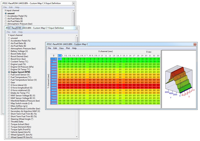
Example Custom Map Inputs (GT-R)
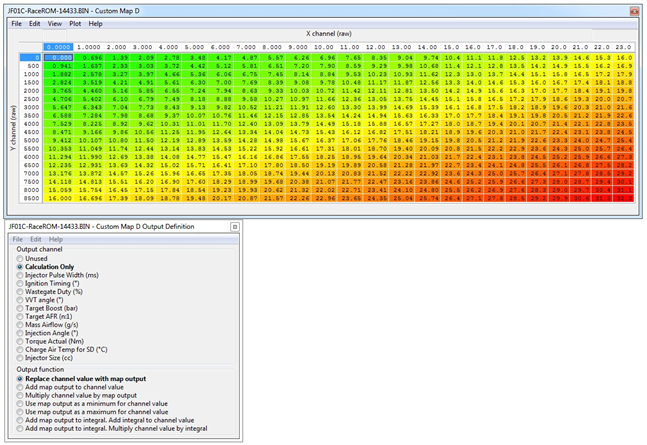
Example Custom Map Outputs (GT-R)
Custom Map Output Functions
Custom Map Notes
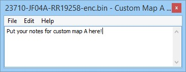
Notes relating to each custom map can be added here. There is a 100 character limit. The “delete” key cannot be used as it’s still a hot-key for triggering live data, and the “Ctrl-S” hotkey combination doesn’t work for the moment so quit and click Yes on the Save Changes To Custom Map X dialog box to save your changes.
Custom Map A, B etc.
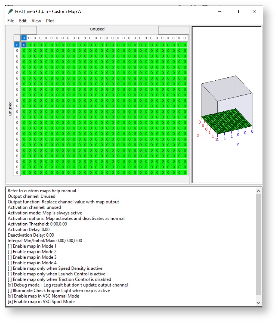
The actual table you'll be using to input/output the values of your choosing. There are a few maps available of different sizes so choose the one best suited to your needs.
The system runs the custom maps in alphabetical order. As such ensure you keep that in mind when utilizing the calculations from one table in another. Or that if you're utilizing them for multiple systems one will be happening first.
E.G. If map A and map B are both replacing the same channel (potentially under different conditions) map A will first replace the value, at which time B will replace A. If set to multiply, or Add, the A calculation will be done first.
Activation Definition
This map sets the method by which this table becomes active or deactivates. There are several options for either setting the system to activate or deactivate given a few different parameters. You can also set it to always active or change state when the user changes map slots or alters the ignition state of the car.
Activation Mode
- Map is always active
This mode means the map will constantly be active and persist through map/mode changes. - Map is only active when channel value is above threshold (With Hysteresis)
Map activates when the top value in the Custom Map Activation Threshold is exceeded. It will then disable when the value goes below the bottom level. In the below example, the map will activate when the activation value goes over 0.475 and becomes deactivated when the value is below 0.5 again.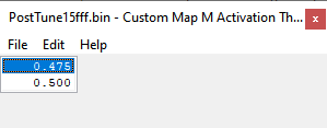
The values of the table don't need to have the lower value on top. The upper value acts as the activation value, and the bottom value when it will deactivate. In the example below, utilizing bar of pressure as the activation, the upper value sets the activation to occur when pressure rises above 3.1 bar of pressure, while it will then deactivate as soon as your pressure goes below 2.9 bar.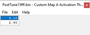
- Map is only active when channel value is below threshold (With Hysteresis)
Map activates when the upper value in the Custom Map Activation Threshold value is achieved. It will then disable when the value goes below the lower level. In the below example, the map will activate when the activation value goes over 0.475 and becomes deactivated when the value is back over 0.5 again.
The values of the table don't need to have the lower value on top. The upper value acts as the activation value, and the bottom value when it will deactivate. In the example below, utilizing bar of pressure as the activation, the upper value sets the activation to occur when pressure boes below 3.1 bar of pressure, while it will then deactivate as soon as your pressure goes above 2.9 bar again. - Map is only active when channel value is between the threshold values
Your map will activate when the activation value is between your two values. You'll want to set the upper value in the map to your low value, and the bottom value to your higher value.
Activation Options
- Map Activates and Deactivates as Normal
The map will activate and deactivate whenever the activation mode is achieved.
Possible uses are things like boost control, traction control, items you want to be on all the time or whenver the vehicle achieves a certain state. - Map Is Initially Inactive. Once Activated, Remains Activate Until Key Off
The map won't become active until the activation threshold or state has been achieved. It will then stay on until the car is turned off at which time it will be disabled until re-enabled.
Potential uses are things like failsafe states where an activation channel goes beyond a certain point at which point timing/speed etc. are reduced until the vehicle is keyed off and on again. - Map Is Initially Active. Once Deactive Remains Inactive Until Key Off.
Your map will be active until a certain state is reached at which time it is diabled. Once disabled it will remain that way until the vehicle is key-cycled off and on, at which point it will be activated again.
Potentially used for things like warm-up maps, cranking etc. Items you want to occur at startup but stop later on.
Activation Delay
Sets the amount of time before the map becomes active after the activation threshold has been achieved.
Activation Threshold
Selects the min/max values for activation parameters. These will be applied to the channel used in the activation definition (If the channel value isn't based on map slot or another function not utilizing a min/max.
For more information on how these thresholds work, check out the Activation Mode section.
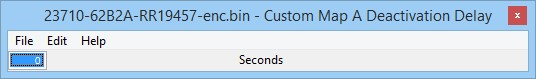
Deactivation Delay
Activation and deactivation now have independent delay times. This means you can trigger a custom map to be active immediately and it will remain on for a time even if the activation conditions are no longer met, for example a 10 second boost target increase.
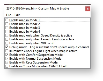
Enable
Chooses when the map should be active. Will still require the activation definition to be met in order for the map to begin working.
If on a platform that offers enable in different vsc modes as well as map modes, keep in mind that it can be in both mode1 and sport mode etc at the same time. Or in the case of GTR, the Suspension Modes. It will need to be activated in both for the table to be utilised.
Each map has a debug mode. This means that the map will be processed when the ECU is calculating the map's output channel, but the result is not used as part of the calculation. This can be used in conjunction with the logging features to test the effect that a custom map would have, but without affecting the operation of the engine. Keep in mind that having debug enabled will cause the map to not make any changes to any outputs.
Each custom map has two logged parameters: interim and result. The values that get logged here depend on the selected output function:
| Output Function | Interim | Result |
|---|---|---|
| Unused | 0 | 0 |
Replace channel value with map output | old channel value | map output |
Add map output to channel value | map output | channel value +(plus) map output |
Multiply channel value by map output | map output | channel value * (multiply) map output |
Use map output as a minimum for channel value | map output | the greater of channel value and map output |
Use map output as a maximum for channel value | map output | the lesser of channel value and map output |
Add map output to integral. Add integral to channel value | integral | channel value + integral |
Add map output to integral. Multiply channel value by integral. | integral | channel value * integral |
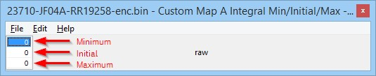
Integral Min/Initial/Max
On our previous Custom Maps implementation the integral function would always start and default back to zero making multiplication via an integral impossible. An initial value of 1 will fix the issue.
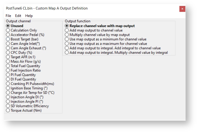
Output Definition
Used to select the output channel for the value calculated by your custom map, as well as what it should do with that value.
Output Channel
There are multiple options that exist for the output channel itself, however they can be lumped into two types.
- Existing Channel Alteration - Performs an alteration based on the Output Function selected to an existing channel in the ECM.
- Calculation Only - Only performs the calculation for the table, this value isn't output to a different channel being used by the ECU. However it is possible to take the calculation output and use it in a different custom map.
Output Funciton
When using an output channel to be altered by the custom map, this function decides what way the output function of your custom map is applied to the output channel.
- Replace channel value with map output - This means the map output will completely replace the value chosen as the output channel overriding any other table outputs.
- Add map output to channel value - Map output will simply be added into the channel value (positive values will have an additive affect while negative values will reduce it)
- Multiply channel value by map output - Uses the map output as a multiplier for the output channel. Use fractions to have a reduction of value, and positive values to increase.
- Use map output as a minimum/maximum for channel value - Uses the value in a manner similar to a limiter based on table output for what the min/max values can be for your channel output.
- Add map output to integral. Add integral to channel value - Adjusts integral value for the channel output by adding the table output.
- Add map output to integral. Multiply integral to channel value - Adjusts integral value for the channel output by multiplying the table output.
X-Axis Input Definition
Selects the input value for the x-axis. You can choose from an array of existing vehicle parameters or the calculation results taken from the various other RaceROM Custom Maps. You can choose whether the table should interpolate values between the different x-axis cells, select the closest, or go to the higher/lower cells.
Y-Axis Input Definition
Selects the input value for the y-axis. You can choose from an array of existing vehicle parameters or the calculation results taken from the various other RaceROM Custom Maps. You can choose whether the table should interpolate values between the different y-axis cells, select the closest, or go to the higher/lower cells.
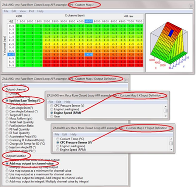
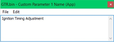
Potentiometer Input Tuning
It’s possible to configure one of the ECU Inputs to adjust a Custom Map. By connecting a 0 – 5v potentiometer to the Input it’s possible to ‘adjust’ an input up and down enabling live or real time tuning.
The X axis is RPM and the Y axis is CPC Sensor Input for the 5v potentiometer.
This example shows Custom Map J will increase (advance) the Ignition Timing dependant on the potentiometer input voltage.
- At 0 volts the ignition timing will not be altered.
- At 5 volts the Ignition timing will be increased by plus 5 degrees.
- So the ignition can be adjusted up and down as required whilst watching power output or knock correction.
This Cosworth BRZ project development testing shows the Injection Firing Angle and Ignition Timing being adjusted simultaneously with two potentiometer voltage inputs, on the GTR there are 7 voltage inputs to play with.
This YouTube video link can be found on the EcuTek You Tube channel by searching Cosworth or follow this link to the video clip http://www.youtube.com/watch?v=bB3PDkSqNo0
The BRZ/FR-S has Dual AVCS (Intake and Exhaust Cam Timing).
We can import two 0v - 5v potentiometers and use them to adjust the Intake and Exhaust cams live and simultaneously.
By creating a log file at the same time simply lock the engine RPM on a dyno on full load then dial the two pots back and forth until the peak power output is seen, once the peak output is displayed then simply release the Accel pedal and re-apply quickly to mark the current VVT angles in the log file for map calibration later on.
Repeat this test at 250 or 500rpm intervals to build the optimum VVT map profiles.
There are various high quality potentiometers available that can be dash mounted for the driver to adjust and fine tune various settings.
Here are a few suggestions:
Dash Mounted Adjustable Boost Control
This can offer the driver fully adjustable boost control, turning the Boost/WG Duty up and down as they wish.
Dash Mounted Adjustable Traction Control
This can be used as weighting factors for traction control allowing the driver to dial in more or less aggressive traction control as required.
Dash Mounted Torque Output Control
Simply turn the power up and down by acting on Torque values or Accel pedal multipliers. This can be Map Switch Mode specific and can make a simply Valet Mode.
Dash Mounted ‘Pops and Bangs’ Control
Configure a custom map to apply a heavy Ignition Retard during lift off, combined this with a rich AFR and the driver can control the intensity of the pops and bangs with the dash mounted control.
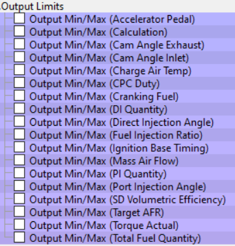
Output Limits
These maps set a minimum or maximum value for what your custom map can output. This prevents unrealistic or extreme values from being used.
Map List
Two Dimensional Maps
While all of the custom maps are three dimensional, if you structure the map carefully you can make a 3d map act as a 2d map. If you set only one input channel (In this case let's use Y) to your desired definition, as long as you add a complete x-axis in ascending order, even with no input, it will use the first column (0). If you fail to have a complete axis in ascending order, the map lookup function may not work properly. Always make sure to fully populate the maps and their axes with sensible values.
Custom Map Output as Input On Another Map.
If you set a custom map as "Calculation Only" as the output channel. That means the result will be calculated and stored for use in other maps.
As you're creating another map, you can then use it as an activation for another map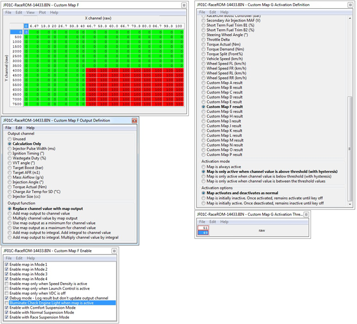
Or it can be used as a complete axis which will use the result of your other table against another input either from the ecu or another custom table.
Integral Output Functions
This feature allows you to create an integral that ramps up or down over a period of time. In the example below, the custom map is processed 100 times per second. This time frame update can vary depending on the vehicle and the selected output and is not adjustable but the values in the map can be increased or decreased to control the increment or decrement rate.
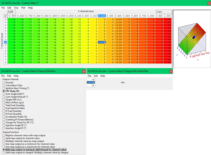
For the purpose of illustration, assume the map result is always 2. The first time the map is processed, the map result is 2, and this gets added to the integral 0 + 2 = 2. Then the integral gets added to the output channel (CPC Duty which is used for Wastegate Duty on BRZ). So the final calculation is (CPC Duty + 2).
One hundredth of a second later the map gets processed again, the result is 2 again, and this gets added to the integral. 2 + 2 = 4. Then the integral gets added to the output channel (CPC Duty). So the final calculation is (CPC Duty + 4) and so this continues.
The integral will start from the Initial value when the custom map becomes active, in the above example the Initial value is set to 0.
The Minimum allowed value is the top value and is set to -8 and the Maximum is the bottom value currently set to 10. The integral will gradually increase (or decrease depending on the X axis input) until the Minimum (-8) or Maximum (+10) allowed Integral value is reached.
This can be used for accurate closed loop boost control or closed loop fuel control on full load on BRZ or Nissan 370z models.
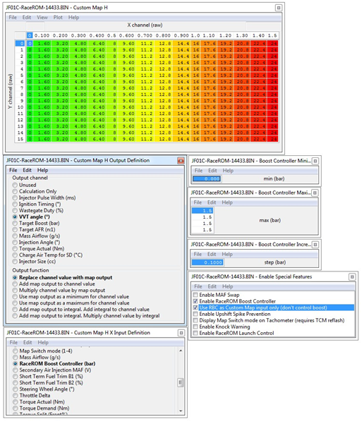
Driver Controlled Input
In the example below, the Custom map is configured to take its X input from the RaceROM boost controller. The output of the Custom map is defined as (VVT) Intake Cam advance. The RaceROM boost controller is enabled configured with a range of 0 to 1.5 bar. The "Use RBC as custom map input only (don't control boost)" checkbox is set.
Using this configuration, the driver can adjust the VVT angle by pressing the cruise control button up and down.
The driver-control option allows a certain amount of live tuning. You can adjust a particular parameter, for example: Injection Angle, while the car is running in order to find the optimum value. You can also use Ignition Timing, Mass Air Flow or Wastegate duty so you can see the change live.
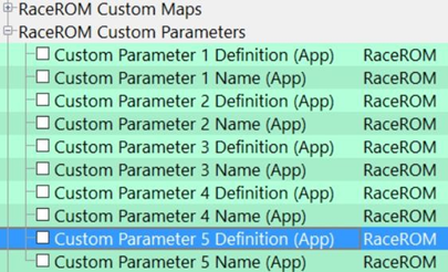
Custom Parameter
Available through the EcuConnect app for compatible vehicles only
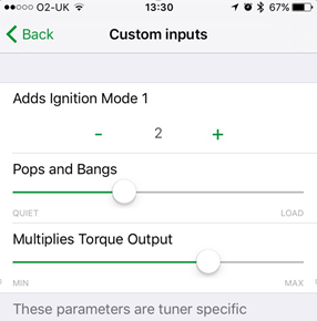
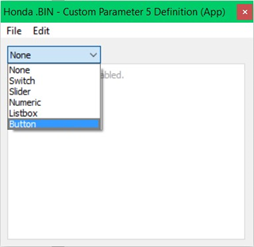
Custom Parameters provides five new inputs into the ECU that can be adjusted using an iOS device, these can be used to adjust Custom Maps. These functions can provide the ability to control features and functions in the factory ECU that were never before possible, and all controlled using a iPhone (or iPad). The five inputs are configured using ProECU and can be setup as a Switch, Slider control, a Numerical value, a List Box, or a Momentary Button. Each of the 5 Custom Parameters have a Definition option – to define how the Custom parameter will work and a Name box where the description for the map can be written and this will be displayed in ECU Connect under the specific custom feature.
Each Custom Parameter, once configured, could be used a Custom Map Input Axis value or even as a Custom Map Activation Definition. When using ECU Connect and a switch is ‘enabled’ or a ‘slider’ moved to a certain position and its ‘above or below’ a threshold then a certain Custom Map would become active. While the Custom Parameter input into a Custom Map could adjust the Ignition, the fueling, the Inlet or Exhaust cam timing (or both at the same time), it could adjust the Injector Firing Angle on a BRZ/86 or DIT. Custom Parameters makes the following features possible...
- Adjustable Boost - set min/max boost with driver-adjustable slider control
- Adjustable Traction Control - use a slider control for live variation of TC gain
- Live Adjustments - use slider or numerical control to add/remove ignition timing, adjust fuelling, vary cam timing or alter custom map outputs
- Live Adjustment - of the power output, also engage solenoids or relays
- Valet Mode - turn this ON or OFF using your handheld device
All these features and many more can be created in Custom Maps and adjusted and controlled using your iOS device, the limitation is simply your imagination. Here are some examples of what is possible:
Honda Civic
Turn the VTEC ON and OFF whenever you like
Configure a pit lane Speed Limiter and even import a gear level switch to enable the map Add and remove Ignition Timing
Adjust the weighting factor on a throttle and/or ignition based traction control Adjust the maximum allowed boost pressure using the slider
Subaru BRZ – FR-S and GT86
Adjust the weighting factor on a throttle and/or ignition based traction control
Add and remove Ignition Timing
Add and remove Mass Airflow for fine tuning low speed drivability
Add a throttle multiplier to create a sharper Accel to Throttle butterfly opening ratio
Create and add a Valet mode on a model that doesn’t have a RaceROM Valet mode feature
Nissan GTR
Add and remove Ignition Timing from a 3d custom map
Adjust the intensity of pops and bangs using a slider
Adjust the ECM torque output value to influence the gearbox TCM clutch control during gearshifts
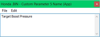
In the example below you can see the Custom Parameter 1 DEFINITION has been configured as a SLIDER and the Custom Parameter 1 NAME is set as ‘Target Boost Pressure’
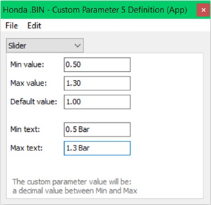
The Min and Max Text will be shown in ECU Connect under the slider bar on the left and righthand side respectively. The Min Value is 0.50 bar (7psi) and the max value is 1.30 Bar (19psi), the Default Value is 1.00bar, this is where the slider will be set in ECU Connect after ECU programming. When using the app (ECU Connect) and by selecting the Custom Parameter option, users not be able to adjust the boost below or above these settings. If the tuner does not wish the customer to adjust the boost pressure at all then do not configure the Custom Parameters 1-5 in ProECU.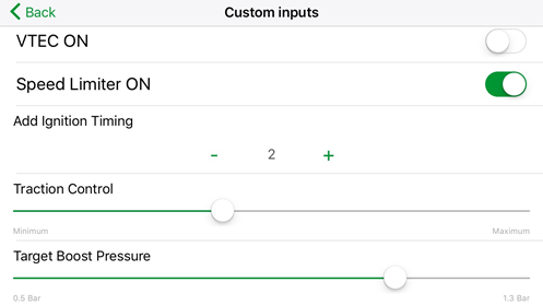
In addition the output value of a Custom Parameter can be logging in ProECU and in ECU Connect The following example will show how ECU Connect could be used to add and remove Ignition Timing using custom maps.
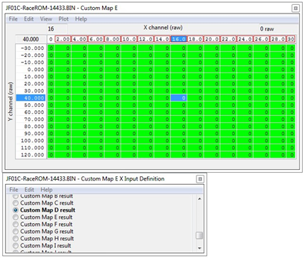
Custom Map E
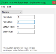
- axis is Custom Parameter 1 which is configured as a Numerical increment
- Axis is Engine Speed (this could be Engine Load for example) Map Output is Adds Ignition Timing
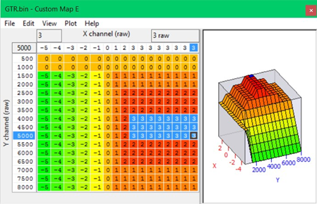
This will appear in ECU Connect as shown below and the custom can REMOVE up to -5 degrees but can ADD up to +3 degrees, but look carefully and you will see that Map E has been configured so the maximum value that can be ADDED at 1500rpm is only 1deg and that increases to 2deg at 2500rpm, this gives the tuner the ability to control how much and where the Ignition will be added. You can also configure the activation setting to say prevent the map from working above or below a certain coolant or air temperature.
Custom Map Examples
Gear Change Fuel cut
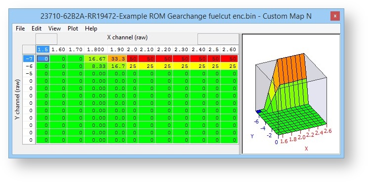
The following example enables a partial fuel cut on gearshift. The result is increased noise on the shift, but can also be used in very high powered cars to get a faster speed match and ultimately a faster shift. You can download the example rom used here by using EcuTek Update:
23710-62B2A-RR19472-Example ROM Gearchange fuelcut enc.bin
A Custom Map N is used to create a partial fuel cut when the ignition timing is below -6º, and the throttle angle is above 68º, this situation is only encountered during a gearshift. Manifold absolute pressure is used to vary the cut level, so at low boost even if at full throttle there will be no cut.
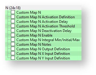
Custom Map N
Custom Map N Activation Definition Activation Channel: Throttle Angle
Activation mode: Map is only active when channel value is above threshold (with hysteresis)
Activation options: Map activates and deactivates as normal
Custom Map N Activation Delay: 0 (zero)
Custom Map N Activation Threshold: Activates above 68, deactivates below 66
Custom Map N Enable: Enabled in mode 4 and all suspension modes in example
Custom Map N Output Definition: Cylinder Cut Probability (%)
Custom Map N X Input Definition: Manifold Absolute Pressure (bar)
Custom Map N Y Input Definition: Ignition Timing (º)
Throttle angle typically ranges from 0 to 74 in live data and custom maps.
Map List
Custom Maps Boost Control
While no longer necessary on many platforms with the introduction of RaceROM Boost Control, instructions on how to create a custom boost control system can show you the different options and methods for how to use this feature. For more information on the RaceROM boost control system check out our complete guide
By using custom maps it possible to rewrite the factory boost control system, this can be useful when tuning for larger turbo’s, stronger actuators and external wastegates.
You can set the wastegate duty as a fixed WG duty % for a target boost pressure, this is a very crude and basic open loop boost control system but it can be useful when setting up a heavily modified vehicle where there are a lot of variables at the start of the tuning.
Once the Ignition and Fuel calibration is dialled in then you can enable the proportional and integral compensations for the current ‘boost error’. This will create a fully closed loop boost control system.
If you wish to use the boost control in open loop then simply do not enable the proportional or integral maps or simply enable them in other modes (like Mode3 or Mode4) so you can see the affect they have on the WG duty.
The example below shows 3 custom maps configured for a custom boost control setup.
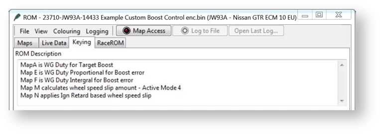
Map A is WG Duty for a Target Boost pressure
Map E is WG Duty Proportional addition for boost error
Map F is WG Duty Integral addition for boost error
The current Target Boost pressure is output of the 3d ‘Target Boost’ map, the RaceROM Boost Controller (RRBC) is then considered.
The current target boost is always the lowest boost target value, so if the output of the 3d ‘Target Boost’ map is 1.2bar but the RRBC setting is 0.9bar then the Target Boost Pressure is 0.9bar and this will be the X axis input value for Map A.
But if the current RRBC setting is 1.4bar then the Target Boost Pressure would be 1.2bar.
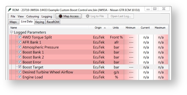
You can see and log the current Target Boost value shown under Live Data.
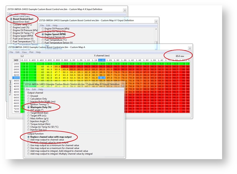
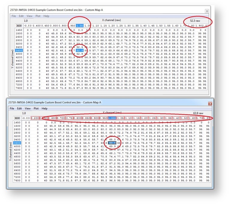
Custom Map A – Wastegate Duty for a Target Boost Pressure
- X axis is Target Boost Pressure (bar)
- Y axis is Engine Speed (rpm)
- Map values are Wastegate Duty (%)
The map output will be the Wastegate Duty% for the current Target Boost pressure.
This will overwrite the factory WG duty control.
In this example below at 3400rpm and 1.2bar Boost Target the WG Duty will be 65%.
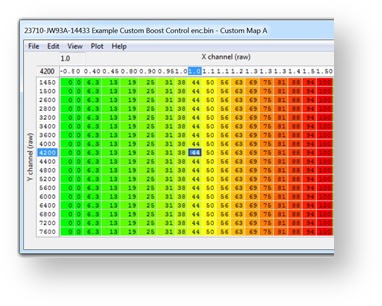
Using RRBC its very easy to calibrate and create a base WG Duty Map A profile using the following tequnique but ensure no proportional or Integral maps are enabled.
Fill Map A columns with 0 to 100% values like shown to the left then make a few power runs starting at 0.7bar and increse the RRBC in 0.1bar incremements and log the results. You can now see what boost pressure is created for a given WG Duty.
So if 20% WG Duty makes 0.9bar then enter 0.9 in the X axis column above the 20% column. If 40% produces 1.1bar and 60% produces 1.3bar then simply enter the boost value in the X axis above the corresponding WG Duty column.
Custom Map E - Wastegate Duty Proportional Control
- X axis is the current boost error (Bar)
- Y axis is Engine Speed (RPM)
- Map values are Wastegate Duty proportional compensation factor.
Custom Map E will add the map output value to the current WG Duty (output of Map A) for a given RPM and Boost Error.
In the example shown below the X axis is boost error (the difference between the Target Boost and Manifold Relative Pressure MRP). The Y axis is Engine Speed.
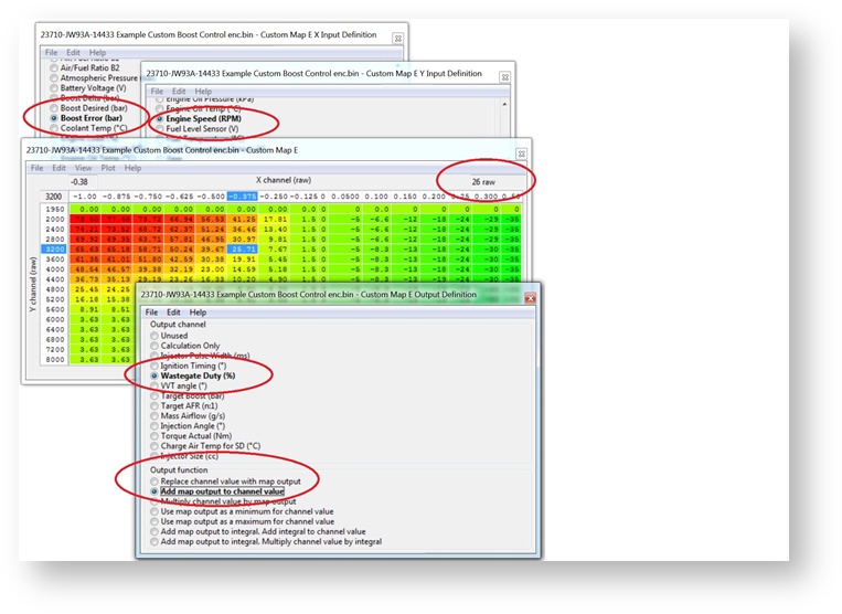
In this example above at 3200rpm and -0.375bar boost error (so under the boost target) Map E will ADD a value of 26 to the current WG Duty therefore increasing the WG Duty.
Assuming the current value for Map A to be 65 then the WG duty will increase to 91 (65 + 26) to give a final WG Duty of 91%.
As the boost (MRP) increases and nears the boost target then the size of proportional value added will decrease accordingly and as the Boost Target is achieved the proportional amount added will be zero.
If the boost overshoots the target boost value then Map E will REMOVE WG Duty as well.
NOTE: The Proportional value (output of map A) is a one time only added addition and it does not accumulate like an Integral value will do.
Calibrating the Proportional Custom Map
We suggest that the proportional and integral maps are not enabled until Map A for base WG Duty has been profiled and is fairly close for good tight boost control.
We then suggest you create an overboost condition and then enable the proportional and integral maps in other modes to see the individual results.
The following sequence is great for producing an accurate proportional or integral map.
Ensure Map A is accurately calibrated so it delivers the correct boost pressure for a given target boost pressure then simply ADD minus -0.20bar to the X axis as shown below.
So now the column for 1.2bar becomes 1.0bar and WG Duty increases from 52% to 64%. When you select 1.0bar with RRBC you will get 1.2bar and you can see how the Proportional control deals with the overshoot, log the INTERIM and RESULT of Custom Map E to see the proportional component working.
If the boost reduces from 1.2bar to 1.1bar then you have to increase the proportional values for a 0.1bar boost error so the boost can be reduced further.
If the boost reduces from 1.2bar down to 0.9bar then you have to reduce the proportional values in Map E for a 0.1bar boost error.
We suggest you double or halve the values in Map E to increase or reduce the boost accordingly. The proportional addition should correct the boost instantly and there should be no over or undershoot if the proportional values are correct.
In fact the output of Map E (Map A WG duty plus Map E Proportional WG Duty component) should be the actual the WG duty value shown in Map A before you rescaled the X axis.
Further on from this if you have not rescaled Map A X axis then the output of Map E shows the values you should enter into Map A at a given RPM if the boost error is zero(as Map E has corrected the WG Duty to produce the Target Boost pressure you have demanded).
This method can soon populate an accurate proportional map suitable for the size of your turbocharger.
Once your proportional map is calibrated then turn off Map E and enable Map F to calibrate Integral map in the same way.
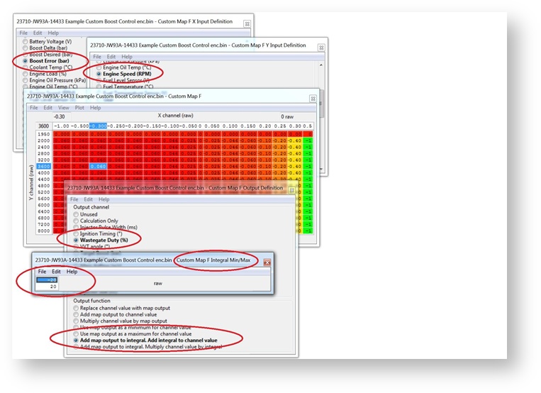
Custom Map F - Wastegate Duty Integral Control
- X axis is the current Boost Error (Bar)
- Y axis is Engine Speed (RPM)
- Map values are Wastegate Duty Integral compensation factor.
In the example shown below the X axis is boost error (the difference between the Target Boost and Manifold Relative Pressure MRP). The Y axis is Engine Speed.
Custom Map F output value will be added the current WG Duty but as an integral, so the value will keep increasing over a period of time (several times a second).
The proportional value (output of Map E) will also be added if the proportional map has been enabled.
In this example at 3600rpm and -0.3bar boost error (so under the boost target) Map F will ADD a value of 0.06 to the current WG Duty (Map A plus Map E) therefore increasing the WG Duty. Assuming the current value for Map A to be 65 and Map E to be 26 then the WG duty will increase from 91% to 91.06% (65 + 26 + 0.06).
But as the Output Definition is ‘Add map output to Integral, Add Integral to Channel’ then this 0.06 value will quickly increment on each calculation therefore causing the WG Duty to rise quickly over a time period for a continuous boost error.
If the boost pressure overshoots the Target Boost value then Map F Integral component will also REMOVE WG Duty.
If the rate of change (Increment or decrement) is too fast then halve the values and retest. If the rate of change is too slow then double the values and retest.
The Integral Min/Max has been set so it can only add or subtract a maximum value of 20, this prevents the Integral from drastically changing the WG duty over a time period like during spool and part throttle conditions.
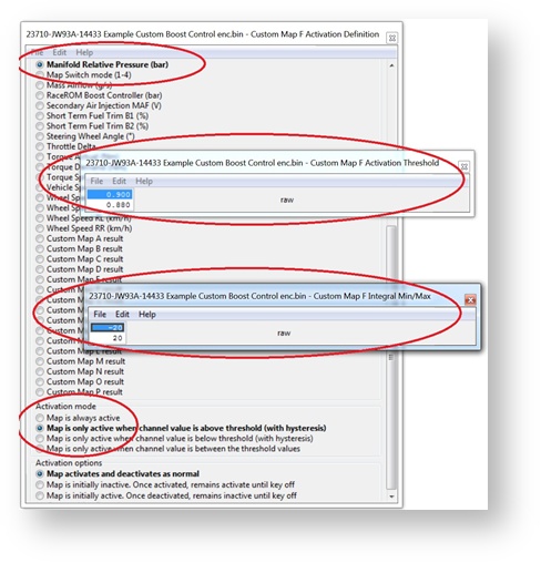
To further improve the boost control logic the Integral control (Map F) has been configured with an Activation Definition.
As shown below the Integral control (Map F) is only allowed to work when the MRP is over 0.9bar and it will stop working below
0.88bar. So the Integral control can only adjust the WG Duty on full load. This will prevent the Integral from ramping up (or down) the WG Duty at part throttle conditions.
Calibrating the Integral Custom Map
The Integral will not correct the boost instantly like the proportional map does, the Integral takes times and you will see the boost reduce (or increase) over a time period (0.1 to 2 seconds). If the Integral takes too long to correct the boost pressure then double the values in Map F so the WG Duty reduces more quickly.
If the WG Duty redcues too quickly and the boost begins to oscillate then halve the values until the boost is more stable and then fine tune.
We cannot adjust the frequency of the integral addition but doubling or halving the values will have the same affect.
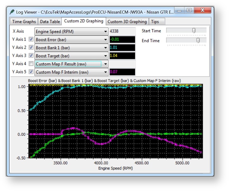
Below you can see an integral addition in action past 3500rpm when the activation pressure of 0.9bar was exceeded.
You can see the purple integral value (Map F Interim) constantly adjusting the WG Duty to maintain a zero Boost Error.
Our example screen shots and example ROM files have the proportional and integral values calibrated for stock turbo’s, larger turbo’s and stronger actuators will need smaller values in the maps (in theory).
Additional Boost Control calibration
Other compensation factors can also be created, some examples below.
- Target boost pressure compensation for Coolant and Air temperature
- Per Gear Target Boost and WG Duty compensation
- Air Temp and Atmospheric pressure compensation
Note these compensations should be applied before any Proportional and Integral maps are implemented (so created as Map B, Map C or Map D)
Custom Maps Boost Limit
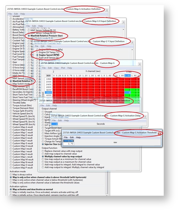
In addition a custom map can be used as a boost limit, this is useful if the boost is over 1.7bar and only 1 x 4bar map sensor is fitted in the plenum (Inlet Manifold) or a Speed Density kit is used where the charge air sensor is built into the MAP sensor but a 4bar sensor is not available. If the pre throttle map sensor sensors are NOT changed then they cannot read over 1.73bar and therefore cannot be used for an overboost fuel cut protection.
In this case set the Boost Limit (RaceROM) map to 1.9bar or greater so this limiter can never be reached (as standard MAP sensors can only read to 1.73bar) then we can configure a Custom Map as a boost Limit like shown below.
The X axis is MRP from the Plenum MAP sensor, the Y axis is RPM the output will multiply the Injector Size by 1 or 0. Note the X axis at 1.8bar will multiply the Injector size by 1 so will NOT change the Injector open time but at 1.81 will multiply the Injector size by zero which will cut the Injectors.
The activation for Custom Map G is set at 1.75 bar so the fuel cut cannot happen below this pressure but the resume is set to 1.1bar before the Injectors will restore, the timer activation is set at 1 second so quick spikes will not result in a fuel cut.
Custom Map B - Calculating Boost Error (GT-R)
The difference between the Target RRBC value and the current Boost MRP is the boost error and this is stored as the Custom Map B Output. In the example screen shots shown below the RRBC target is 0.8bar but the MRP is actually 1.2bar so an overboost of 0.4bar (Custom Map B output)
- X axis is the RaceROM Boost Controller input (Bar)
- Y axis is Manifold Relative Pressure (Bar)
- Map values are Boost Error amount (Bar)
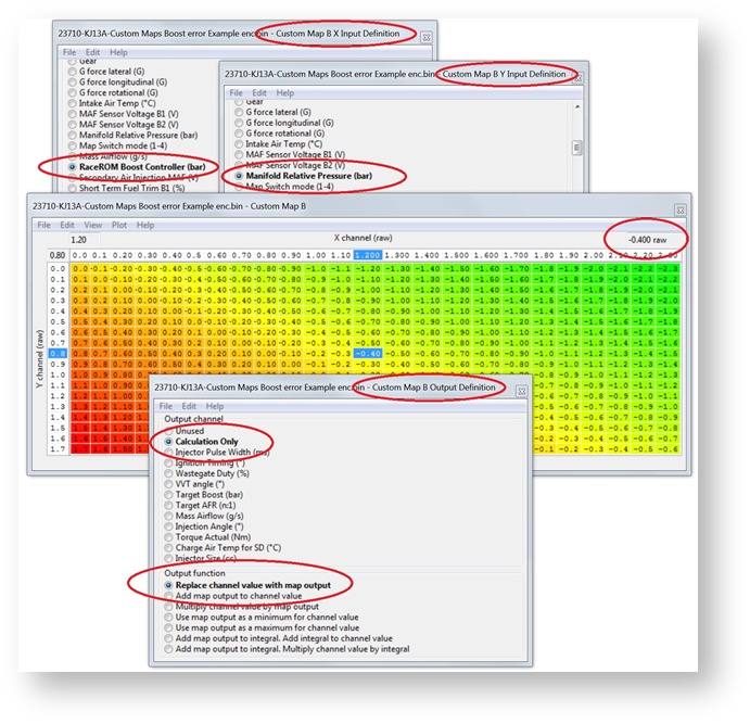
You can now use this Custom Map B boost error value as an input to the proportional or integral Wastegate duty maps like Map E or F on the previous Custom Maps Boost Control examples.
In this example we have set Custom Map C as a proportional map and in this situation Custom Map B Result of 0.4bar overboost would ADD -25% to the Wastegate Duty (so reduce the WG Duty by 25%).

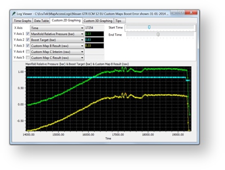
You can see from the example log file screen shot that follows the RRBC target is 0.83bar (CYAN Line) but the current MRP is 1.13bar (GREEN Line) and the Custom Map B result shows the current boost error (YELLOW line).
If you want to keep the same Custom Maps Boost Control example as shown previously (How to set up Custom Maps Boost Control) then make the following changes to the maps A, E and F.
- Map A: change Desired Boost to RaceROM Boost Control as the X axis Input
- Map E: change the X axis Boost Error input to the Output of Custom Map B
- Map F: change the Y axis Boost Error input to the Output of Custom Map B
In addition add Custom Map B as a new map so it can calculate Boost Error using the plenum based 4bar map sensor.
Note the pre throttle map sensors cannot and should not be removed as a DTC will occur and the ECU will enter SAFE Mode , in addition the WG Duty will drop to 0%. If the Boost Sensor DTCs are disabled then the ECU will still be in safe mode so we advise that you leave them connected at all time.
Custom Check Engine Light / Failsafe
When adding in additional modules or equipment, or driving the car hard, it never hurts to have advanced warning if something has gone wrong or is about to. In this section we'll walk through setting up a check engine light to let you know if something has gone wrong.
Establish What Will Happen
First up, figure out what sort of result you'll have if there's a failure, and how it will affect one of the items found in the Activation Defintion list. In this instance we're using a flex fuel kit routed in place of the rear o2 sensor on a circuit racing car. So in the event that the flex fuel module has failed, you'll see voltage drop in the channel O2 Sensor #2 (V).
What Response Do You Want
Now we'll decide what we want to have happen. In this example, we're going to keep it simple with just a check engine light. However you could also use one of the maps to reduce ignition timing, throttle, Torque Requests, or use it to alter another custom map or target. A simple table that reduces accelerator position using a multiplier against the voltage is an easy way that alerts the driver something is up, without completely halting a car in it's tracks. Set up a response relative to the danger of what a failure could cause.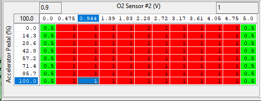
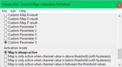
Set Up CEL Activation
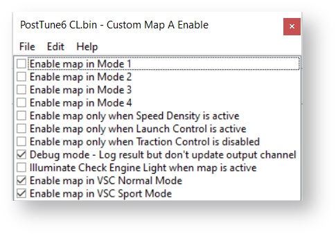
- Head over to the Custom Map Enable field. Select the modes you want it to be active in. In this case we want it to occur regardless of mapswitch mode andVSC mode so we'll leave them all checked. We'll also select "Illuminate Check Engine Light when map is active" as that's the main goal of this example!
- Save your changes to that table then head over to the Activation Definition. For Activation Channel we're going with O2 Sensor #2 (V). We also want the map to activate if the problem is happening below the minimum voltage so we'll select Map is only active when cahnnel is below threshold (with hysteresis). Lastly since this is a CEL we don't want it to be active all the time, or activate and deactivate whenever it occurs, as we want to know it has happened once, so we can then check things out. So we'll go with the option Map is initially inactive. Once activated, remains activate until key off. This means once the CEL is on, it will stay on until the car is turned off making sure you're alerted to it happening.
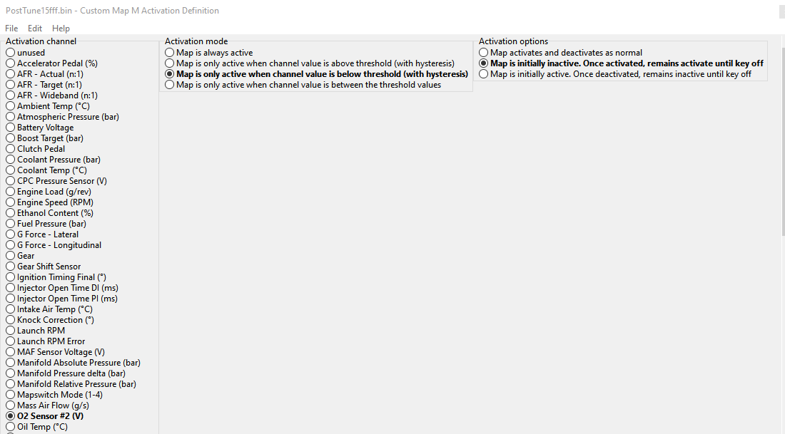
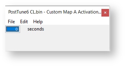
- To keep from having any issues with electrical interference we'll set a small delay under Custom Map Activation Delay of 1 second.
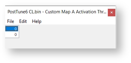
- For this module anything below 0.5v is abnormal and indicates an issue. To account for small variances in voltage and since .5v also indicates 0 ethanol content, we'll go ahead and set the lower threshold for activation to 0.475v and the upper deactivation limit to 0.5v. (keep in mind the way things are setup, it will only deactivate after key-off).

- Now we can go ahead and flash the changes to the car. The simple way to test things out in this case are to cause the CEL to occur by simply unplugging the module. If a CEL has activated you're good to go!
How to set up Traction Control
By using the Custom maps and our powerful 4 channel wheel speed logging, it's possible to create a torque reduction map for wheel speed differential.
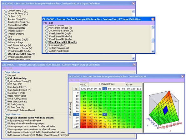
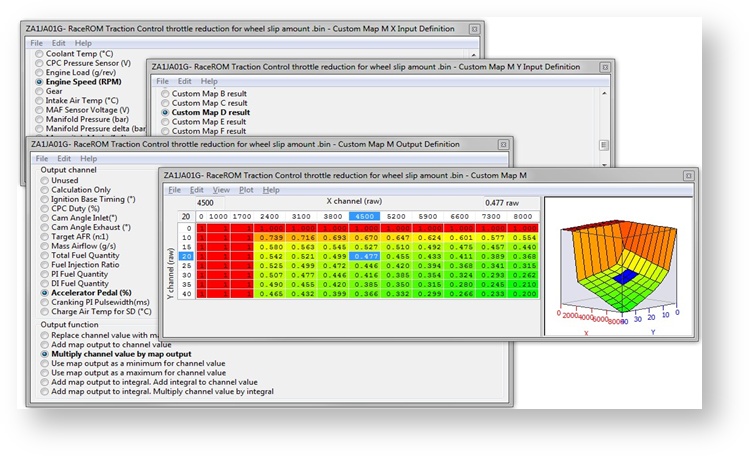
For this example we utilized Custom Map M. Starting off we set the x axis to wheel speed front right and the y-axis to rear right. We then set up a table that would give us an idea of how much wheel slip there was.
The map will only output a value if the rear wheel speed is greater than the front wheel speed, as the vehicle is rear wheel drive this should always be the case.
If the front wheels are doing 40kph and the rear wheels are 70kph then the wheel speed differential is 30kph, this value is then stored as the Custom Map M Result.
We then created a map using Custom Map N. We used the result of our Custom Map M wheel slip map as the y-axis, and RPM as the x axis. We chose to output our value to ignition base timing and to avoid massive corrections we chose to add the map output to the channel value. Given that the table is set up for a subtractive value it should reduce the amount of base timing, thereby reducing the amount of torque the engine is outputting when slip is seen.
We've set up the map to be progressive allowing a small amount of slip before it makes aggressive corrections. We also increased the correction value the higher the RPM.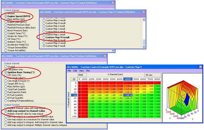
Further maps can be added for vehicle speed where multipliers could be used to differentiate between a low speed acceleration wheel slip (1st or 2nd gear) vs a fast corner ‘high speed‘ drift situation where you may want to dampen the torque rather than completely kill the torque.
Accelerator pedal output can also be intercepted to create a throttle based traction control strategy with the addition of ignition retard and steering angle inputs for further wheel slip control.
EcuTek ProECU tuning tools tools should only be used by experienced tuners who understand the product and engine calibration.
If you do not fully understand this product then you WILL damage your engine, ECU or your vehicle.
Please ensure you fully read all EcuTek manuals BEFORE attempting to use ProECU with your laptop or your vehicle.
Use with extreme caution and understanding at all times, if in doubt then do not proceed.
EcuTek accepts no responsibility for any damage to the engine, ECU or any part of the vehicle that results directly or indirectly from using the product.
** If you are in any doubt that you do NOT have the experience required to use this product then you should NOT USE IT **
Retail customers
** If you have any doubt that you do NOT have the experience required to use this product then you should NOT USE IT, you should simply contact your EcuTek Master Tuner shown clearly on the top of your Programming Kit or visit your preferred tuning shop to have a professional tuner use it for you **