RaceROM Boost Control
- Brandyn Mowat
![]()
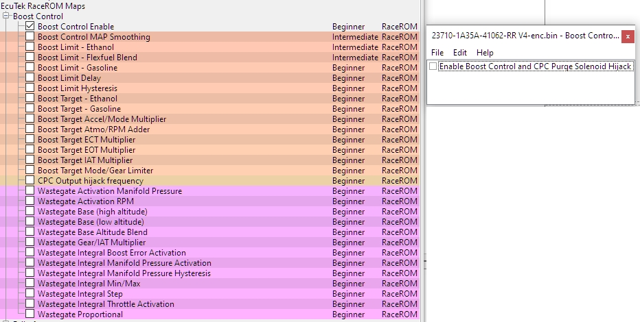
RaceROM Boost Control
RaceROM Boost Control
We now have boost control hardcoded into the RaceROM files so you won't need to make custom maps to control forced induction. This is done entirely by the factory ecu utilising the CPC control valve. You can now set up and tune boost control with a large degree of freedom and control allowing you to safely achieve the power boost available from forced induction.
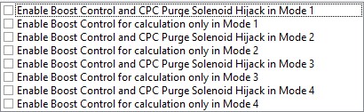
Enabling RaceROM Boost Control
To enable RaceROM boost control it's just a simple toggle that (on most platforms) changes your CPC signal over from factory behaviour to the boost control maps.
CPC Output Hijack Frequency
When using Boost control (and custom maps CPC output) the OEM functionality is completely overwritten by this function and the valve is driven at this set frequency. On some vehicles this frequency isn't capable of being adjusted due to limitations of the ecu.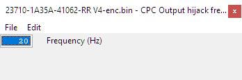
Boost MAP Control Smoothing
The output of the MAP sensor can be smoothed for the purposes of boost control. 0 is maximum smoothing 1 is no smoothing.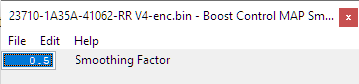
Tuning RaceROM Boost Control
To properly tune the boost control system you'll want to start by setting sensible limits and targets first to ensure that the boost control maintains sensible and safe levels as you slowly ramp things up. From there you'll start dialling in the wastegate closed loop behaviour as needed in order to hit your targets.
Basic Operation of Boost Control System
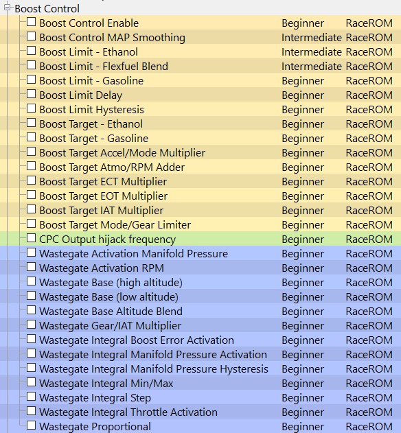
Map List
Live Data Parameters
- Boost Target – Absolute pressure target in bar, measured by the intake manifold pressure sensor
- Boost Error – Difference between MAP and Boost Target, positive numbers are over boost
- Manifold Absolute Pressure – Absolute pressure in bar, measured by the intake manifold pressure sensor
- WG Final Duty – The duty cycle applied to the wastegate solenoid (Same as Final Duty)
- WG Duty Base – Output from Wastegate Duty Base maps
- WG Duty Adder – Correction resulting from Gear/IAT multiplier step
- WG Duty Integral – WG duty added by Integral correction of EcuTek boost control strategy
- WG Duty Proportional – WG duty added by Proportional correction of EcuTek boost control strategy
Boost Limits
The Boost Limit function is integrated with the flex fuel systems the system works as shown in the diagram below. When a limit is exceeded a fuel cut will cut fuel to all cylinders.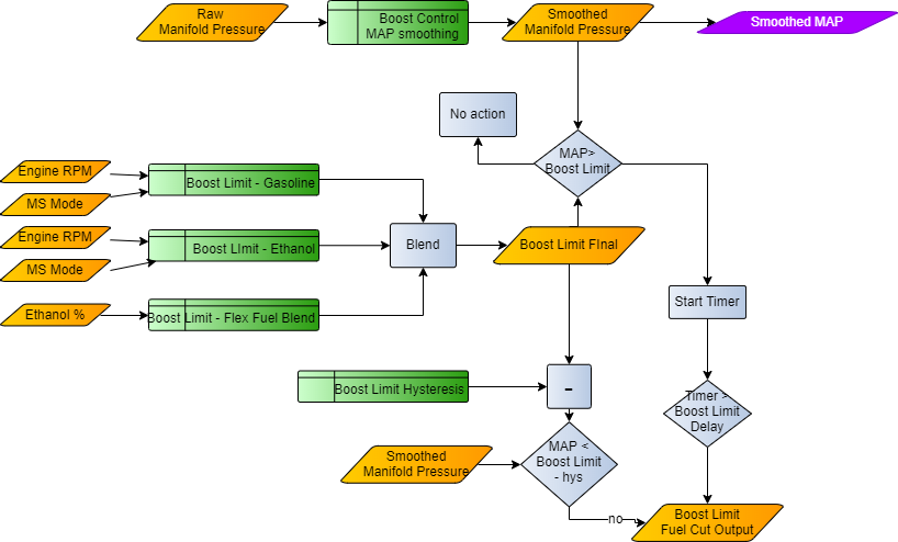
Boost Limit - Gasoline
The manifold absolute pressure needs to exceed final blend between this limit and Boost Limit -Ethanol, measured in Bar by the manifold pressure sensor, for a time that exceeds Boost Limit Delay, to trigger an fuel Cut as an overboost safety measure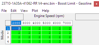
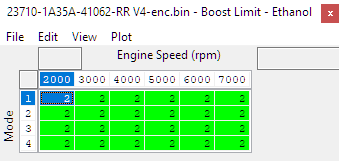
Boost Limit - Ethanol
When running maximum ethanol content scaled in the blend map the manifold absolute pressure needs to exceed this limit at Maximum ethanol blend, measured in Bar (relative) by the manifold pressure sensor, for a time that exceeds Boost Limit Delay, to trigger a Fuel Cut as an overboost safety measure.
Boost Limit -Flex Fuel Blend
The manifold absolute pressure needs to exceed this limit, measured in Bar (relative) by the manifold pressure sensor, for a time that exceeds Boost Limit Delay, to trigger an Accel Cut as an overboost safety measure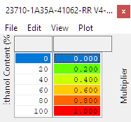
Boost Limit Delay
Time period in milliseconds the ECU will wait before triggering the boost limit fuel cut when the manifold relative pressure exceeds the boost limit as set by the final boost limit value blended between Boost l Cut.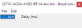
Boost Limit Hysteresis
With the default limit of 2Bar and hysteresis of 0.4Bar, the fuel will be cut when the MAP exceeds 2Bar for 0.3 seconds and resume when the MAP drops below 1.6Bar.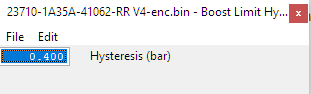
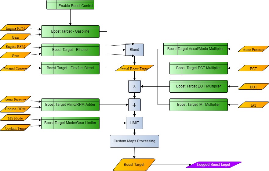
Boost Targets
The Boost Target is defined by gear and RPM, this target output is blended for ethanol content (using the Boost Target – Flex Fuel Blend) and throttle modulation coming in the form of a simple 3D map (Boost Target Accel/Mode Multiplier). There is also a corresponding boost target for Flex Fuel operation named Boost Target - Ethanol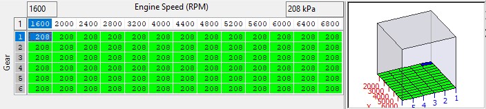
The eventual boost target is calculated as:
𝐵𝑜𝑜𝑠𝑡 𝑇𝑎𝑟𝑔𝑒𝑡 =((𝐵𝑜𝑜𝑠𝑡 𝑇𝑎𝑟𝑔𝑒𝑡 Gasoline ∗(1−𝐹𝐹 𝐵𝑜𝑜𝑠𝑡 𝑇𝑎𝑟𝑔𝑒𝑡 𝐵𝑙𝑒𝑛𝑑))+(𝐵𝑜𝑜𝑠𝑡𝑇𝑎𝑟𝑔𝑒𝑡Ethanol ∗ 𝐹𝐹𝐵𝑜𝑜𝑠𝑡𝑇𝑎𝑟𝑔𝑒𝑡𝐵𝑙𝑒𝑛𝑑)
An RPM dependent target boost profile is set on a per gear basis. Typically gears 1 and 2 have noticeably lower targets due to traction limitations.
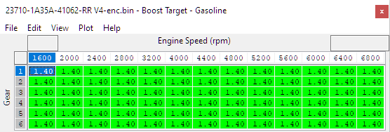
Boost Target – Gasoline
This is the Boost Target for pump gas as defined by gear and RPM. The target is blended with the Ethanol map according to the current ethanol content. The final target also has throttle modulation coming in the from of a simple 3D map (Boost Target Accel/Mode Multiplier). There is also a corresponding boost target for Flex Fuel operation named Boost Target - Ethanol
Boost Target – Ethanol
This is the Boost Target for the maximum calibrated ethanol content defined by gear and RPM, the target is blended with Gasoline map according to the current ethanol content. The final target also has throttle modulation coming in the from of a simple 3D map (Boost Target Accel/Mode Multiplier). There is also a corresponding boost target for Flex Fuel operation named Boost Target - Gasoline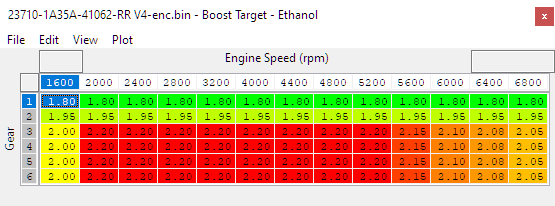
FF Boost Target Blend
Percentage modifier to the boost target based on the ethanol content. Typically set so that a higher percentage of the boost target is used as the ethanol content increases.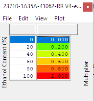
Boost Target Atmo/RPM Adder
The boost target can be offset for changes in atmospheric pressure the default map values reduce the absolute boost target 0.1Bar for each 0.1Bar drop in atmospheric pressure. This is suitable for small turbos which will often be pushed to their maximum at sea level, and pushing the same absolute pressure at altitude can be detrimental to the turbos while not giving the desired pressure.
If working with turbos that have plenty of headroom at sea level then flattening this map to 0 will give the same absolute pressure target at altitude, and result in similar power levels at varying altitude.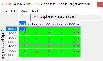
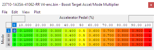
Boost Target Accel/Mode Multiplier
Allows a different multiplier for the boost target based on the amount of accelerator pedal output and what mode (map slot) the vehicle is in. The boost target as adjusted by the Boost Target Atmospheric Correction map is multiplied by the output of this map. For example, a target of 2.4bar * 0.45 = 1.08bar absolute.
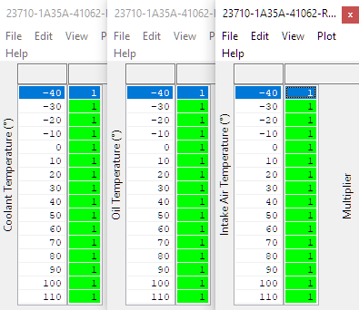
Boost Target ECT/EOT/IAT Multiplier
Boost target multipliers based on Engine Coolant Temperature (ECT), Engine Oil Temperature (EOT) and Intake Air Temperature (IAT). In place to keep the vehicle safe should it see high temperature values. The boost target is multiplied by the output of these maps.
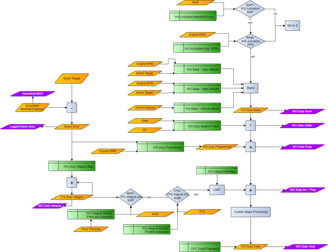
Wastegate Duty - Overview
The closed loop control for wastegate control consists of a base wastegate duty that is blended from a high and low altitude base map into a base multiplier for IAT/Gear. The base duty is always subject to a proportional correction, and an integral correction term is calculated and added only when MAP, Boost Error and Throttle Angle tests are met. There is an overall enable of boost control based on RPM, and the wastegate duty is always zero if the engine speed is below this RPM threshold.
WG Activation RPM
The wastegate solenoid will not be active until this RPM is reached.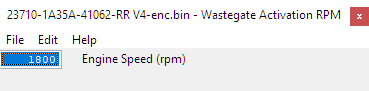
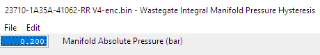
WG Activation Manifold
The wastegate solenoid will not be active until this MAP has Been exceeded.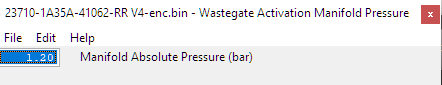
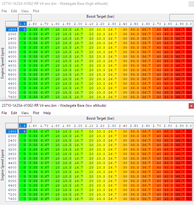
WG Base Duty (low altitude) & WG Base Duty (high altitude)
These two maps are used to set a base duty for high and low altitudes, which are combined using the Wastegate Base Altitude Blend map. The X axis is target boost in Bar(absolute) and the Y axis is engine speed.
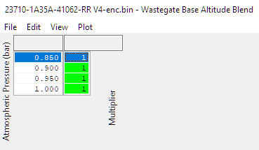
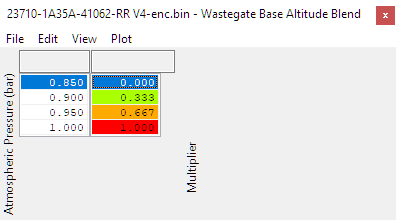
WG Base Altitude Blend
This map defines how the high and low altitude base maps are combined to produce the wastegate base duty. A value of 1.0 uses only the value from the low altitude (sealevel) base map, a value of 0.0 uses only the value from the high altitude base map.
 The final value for WG Duty Base is calculated as:
𝑊𝐺 𝐷𝑢𝑡𝑦 𝐵𝑎𝑠𝑒=(𝑊𝐺 𝐵𝑎𝑠𝑒 𝐷𝑢𝑡𝑦 (𝑙𝑜𝑤 𝑎𝑙𝑡𝑖𝑡𝑖𝑑𝑒) × 𝑊𝐺 𝐵𝑎𝑠𝑒 𝐴𝑙𝑡𝑖𝑡𝑢𝑑𝑒 𝐵𝑙𝑒𝑛𝑑)+(𝑊𝐺 𝐵𝑎𝑠𝑒 𝐷𝑢𝑡𝑦 (ℎ𝑖𝑔ℎ 𝑎𝑙𝑡𝑖𝑡𝑖𝑑𝑒) × (1−𝑊𝐺 𝐵𝑎𝑠𝑒 𝐴𝑙𝑡𝑖𝑡𝑢𝑑𝑒 𝐵𝑙𝑒𝑛𝑑))
The example shown below uses the high altitude base map at 0.85 bar atmospheric pressure and the low altitude base map at 1.00 bar atmospheric pressure with linear interpolation in between.
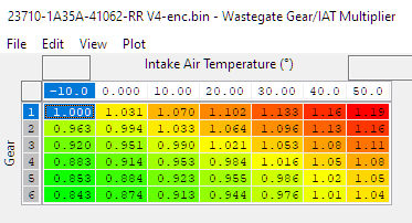
WG Gear/IAT Multiplier
The output of the Wastegate base duty map can be multiplied to increase or decrease it to compensate for changes in intake air temp and/or gear. Typically the base duty is increased with values greater than 1.0 for lower gears (1st/2nd) to improve spoolup with rapidly changing RPM. Conversely the base duty is often decreased with values of less than 1.0 for higher gears (5th/6th) to prevent overboost with increasing load and slower RPM rates.
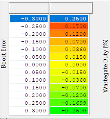
WG Integral Boost Error Activation
A threshold of boost error with hysteresis to enable integral closed loop control of the wastegate duty. Integral feedback is activated when the upper value is exceeded and remains active until the error drops below the lower value. This table can be used to stop integral windup when at full throttle and waiting for the boost to rise.
Integral correction will only begin when the conditions for Boost Error, MAP and Throttle are met, and will be reset to zero if any one of these conditions are not met.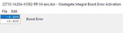
WG Integral Manifold Pressure Activation
A threshold of manifold absolute pressure above which the integral correction is activated.
This table can be used to stop “integral windup” by preventing integral feedback under conditions where the boost control cannot realistically achieve any target boost. The input axis is Atmospheric pressure, and allows the tuner to lower the threshold in line with the drop in atmospheric pressure. Typically this table is set at or slightly below the base pressure for the actuator or wastegate.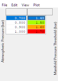
WG Integral Manifold Pressure Hysteresis
Manifold Absolute Pressure must fall below WG Integral Manifold Absolute Pressure Activation by this value for the integral correction to become inactive.
WG Duty Integral Step
Wastegate Integral correction builds up over time. While active (see above conditions) this map dictates how much the integral value is increased with each cycle of the boost control loop. Each loop takes just 10ms (one 1/100 of a second) and the current integral correction can be observed by checking the WG Duty Integral live data parameter which is logged by default.
WG Duty Integral Min/Max
(On some platforms these are separate tables) The integral correction can be limited with these two values. The minimum limit is the top value and the max limit is the lower value. On cars running significantly larger turbos than stock, these values can be scaled down in line with the expected lower wastegate duty. Values of approximately +/- 20% of your max final duty will be a good start.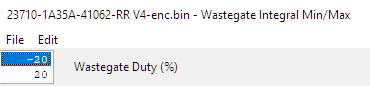
WG Integral Throttle Activation
A threshold of throttle angle with hysteresis to enable integral closed loop control of the wastegate duty. Proportional and integral feedback is activated when the upper value is exceeded and remains active until the throttle angle drops below the lower value. This table can be used to stop overactive closed loop corrections under light load conditions.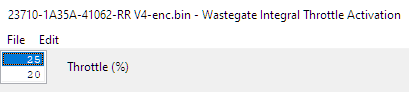
WG Proportional
Proportional correction is absolute wastegate duty added or subtracted at an instant in time based on the current boost error. The default maps have high positive values when the boost is under target at low RPM while in spool up. Using high proportional values is preferable to high integral values to prevent windup but still results in high wastegate duty on spool.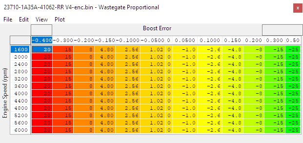
EcuTek ProECU tuning tools tools should only be used by experienced tuners who understand the product and engine calibration.
If you do not fully understand this product then you WILL damage your engine, ECU or your vehicle.
Please ensure you fully read all EcuTek manuals BEFORE attempting to use ProECU with your laptop or your vehicle.
Use with extreme caution and understanding at all times, if in doubt then do not proceed.
EcuTek accepts no responsibility for any damage to the engine, ECU or any part of the vehicle that results directly or indirectly from using the product.
** If you are in any doubt that you do NOT have the experience required to use this product then you should NOT USE IT **
Retail customers
** If you have any doubt that you do NOT have the experience required to use this product then you should NOT USE IT, you should simply contact your EcuTek Master Tuner shown clearly on the top of your Programming Kit or visit your preferred tuning shop to have a professional tuner use it for you **