GT-R RaceROM Custom Maps
- Brandyn Mowat
EcuTek RaceROM Custom Maps is an advanced feature for expert tuners only. It provides the tuner with the ability to modify the control algorithms within the ECU. The tuner can take advantage of this in order to develop their own features that few other tuner can provide. It can also be used to develop one-off fixes to overcome specific problems encountered while tuning a highly modified vehicle. We have improved our unique and innovative Custom Maps feature to enable even more tuning possibilities. With the addition of our dedicated boost control and FlexFuel strategies, all 16 custom maps are now available for the tuners to further exploit the power of RaceROM. Additional inputs and outputs, combined with expanded possibilities for manipulating the values, allow for complex control strategies to be created from something as simple as a fuel pressure fail safe to a slip target based multilayered traction control system. This feature is so versatile it was previously used for things like traction control, flex fuel, and even advanced boost control. While no longer needed for those functions, you can still use these custom maps to do all sorts of additional tasks.
Table of Contents
Custom Map Inputs
Accelerator Pedal
AFR Average
AFR B1
AFR B2
AFR Target Base
Atmospheric Pressure
Battery Voltage
Boost Delta
Boost Target
Boost Error
Boost Sensor B1
Boost Sensor B2
Clutch Slip
Coolant Pressure
Coolant Temp
Engine Load
Engine Oil Pressure
Engine Oil Temp
Engine Speed
FlexFuel Ethanol Content
Fuel Injector Duty
Fuel Injector Effective Pulse
Fuel Injector Pulse
Fuel Level Sensor
Fuel Temperature
Fuel Pressure
Fuel Pressure Relative
Fuel Temperature Sensor
Fuel Trim Combined
Gear
Gear Desired
G Force Lateral
G Force Longitudinal
G Force Rotational
Heated O2 Sensor2 B1
Heated O2 Sensor2 B2
Ignition Timing
Intake Air Temp
Knock Correction
Launch Exit Status
Launch Rpm Target
MAF Sensor Voltage B1
MAF Sensor Voltage B2
Manifold Absolute Pressure
Map Sensor Voltage
Map Switch Mode
- Mass Airflow
RaceROM Boost Controller
Secondary Air Injection MAF
Short Term Fuel Trim B1
Short Term Fuel Trim B2
Steering Wheel Angle
TC Slip Error
TC Torque Reduction
Throttle Angle
Throttle Angle Delta
Torque Actual
Torque Demand
Torque Limit TCM
Torque Limit VDC
Torque Split (Front%)
Upshift Timer
Vehicle Speed
VVT Angle
Wheel Slip Ratio
Wheel Speed Front
Wheel Speed Rear
Custom Map A Result
Custom Map B Result
Custom Map C Result
Custom Map D Result
Custom Map E Result
Custom Map F Result
Custom Map G Result
Custom Map H Result
Custom Map I Result
Custom Map J Result
Custom Map K Result
Custom Map L Result
Custom Map M Result
Custom Map N Result
Custom Map O Result
Custom Map P Result
Custom Input 1
Custom Input 2
Custom Input 3
Custom Input 4
Custom Input 5
Custom Map Outputs
Calculation 1
Calculation 2
Injector Pulse Width
Ignition TIming
Wastegate Duty
VVT Angle
Boost Target Final
Target AFR
Mass Airflow
Injection Angle
Torque Actual
Charge Air Temp for SD
Injector Size
Fuel Pump Duty
Canister Purge Solenoid Duty
Vent Control Valve (0= off, 1=on)
Secondary Air Pump (0= off, 1=on)
Secondary Air Solenoid (0= off, 1=on)
Secondary Fuel Pump (0= off, 1=on)
Cylinder Cut Probability
Throttle Target
Volumetric Efficiency
Torque Limit
Custom Limp Mode
TC Wheel Slip Target
TC Proportional Gain
TC Integral Gain
Custom Map Output Functions
Replace channel value with map output
Add map output to channel value
Multiply channel value by map output
Use map output as a minimum for channel value
Use map output as a maximum for channel value
Add map output to integral. Add integral to channel value
Add map output to integral. Multiply channel value by integral.
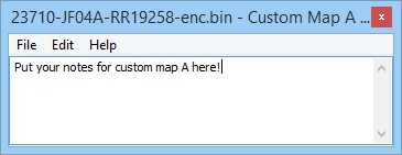
Custom Map Notes
Notes relating to each custom map can be added here. There is a 100 character limit. The “delete” key cannot be used as it’s still a hot-key for triggering live data, and the “Ctrl-S” hotkey combination doesn’t work for the moment so quit and click Yes on the Save Changes To Custom Map X dialog box to save your changes.
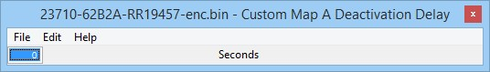
Deactivation Delay
Activation and deactivation now how independent delay times. This means you can trigger a custom map to be active immediately and it will remain on for a time even if the activation conditions are no longer met, for example a 10 second boost target increase.
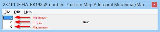
Integral Min/Initial/Max
On our previous Custom Maps implementation the integral function would always start and default back to zero making multiplication via an integral impossible. An initial value of 1 will fix the issue.
Custom Map Examples
Gear Change Fuel cut
The following example enables a partial fuel cut on gearshift. The result is increased noise on the shift, but can also be used in very high powered cars to get a faster speed match and ultimately a faster shift. You can download the example rom used here by using EcuTek Update:
23710-62B2A-RR19472-Example ROM Gearchange fuelcut enc.bin
A Custom Map N is used to create a partial fuel cut when the ignition timing is below -6º, and the throttle angle is above 68º, this situation is only encountered during a gearshift. Manifold absolute pressure is used to vary the cut level, so at low boost even if at full throttle there will be no cut.
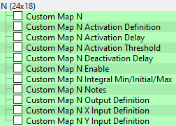
Custom Map N
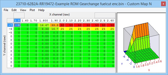
Custom Map N Activation Definition Activation Channel: Throttle Angle
Activation mode: Map is only active when channel value is above threshold (with hysteresis)
Activation options: Map activates and deactivates as normal
Custom Map N Activation Delay: 0 (zero)
Custom Map N Activation Threshold: Activates above 68, deactivates below 66
Custom Map N Enable: Enabled in mode 4 and all suspension modes in example
Custom Map N Output Definition: Cylinder Cut Probability (%)
Custom Map N X Input Definition: Manifold Absolute Pressure (bar)
Custom Map N Y Input Definition: Ignition Timing (º)
Throttle angle typically ranges from 0 to 74 in live data and custom maps.
Map List
How to set up Custom Maps Boost Control
While no longer necessary with the introduction of RaceROM Boost Control, instructions on how to create a custom boost control system can show you the different options and methods for how to use this feature. For more information on the RaceROM boost control system check out our complete guide
By using custom maps it possible to rewrite the factory boost control system, this can be useful when tuning for larger turbo’s, stronger actuators and external wastegates.
You can set the wastegate duty as a fixed WG duty % for a target boost pressure, this is a very crude and basic open loop boost control system but it can be useful when setting up a heavily modified vehicle where there are a lot of variables at the start of the tuning.
Once the Ignition and Fuel calibration is dialled in then you can enable the proportional and integral compensations for the current ‘boost error’. This will create a fully closed loop boost control system.
If you wish to use the boost control in open loop then simply do not enable the proportional or integral maps or simply enable them in other modes (like Mode3 or Mode4) so you can see the affect they have on the WG duty.
The example below shows 3 custom maps configured for a custom boost control setup.
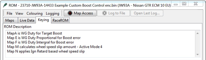
Map A is WG Duty for a Target Boost pressure
Map E is WG Duty Proportional addition for boost error
Map F is WG Duty Integral addition for boost error
The current Target Boost pressure is output of the 3d ‘Target Boost’ map, the RaceROM Boost Controller (RRBC) is then considered.
The current target boost is always the lowest boost target value, so if the output of the 3d ‘Target Boost’ map is 1.2bar but the RRBC setting is 0.9bar then the Target Boost Pressure is 0.9bar and this will be the X axis input value for Map A.
But if the current RRBC setting is 1.4bar then the Target Boost Pressure would be 1.2bar.
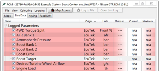
You can see and log the current Target Boost value shown under Live Data.
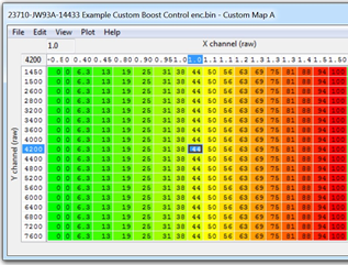
. Custom Map A – Wastegate Duty for a Target Boost Pressure
- X axis is Target Boost Pressure (bar)
- Y axis is Engine Speed (rpm)
- Map values are Wastegate Duty (%)
The map output will be the Wastegate Duty% for the current Target Boost pressure.
This will overwrite the factory WG duty control.
In this example below at 3400rpm and 1.2bar Boost Target the WG Duty will be 65%.
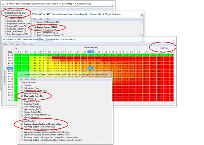
Using RRBC its very easy to calibrate and create a base WG Duty Map A profile using the following tequnique but ensure no proportional or Integral maps are enabled.
Fill Map A columns with 0 to 100% values like shown to the left then make a few power runs starting at 0.7bar and increse the RRBC in 0.1bar incremements and log the results. You can now see what boost pressure is created for a given WG Duty.
So if 20% WG Duty makes 0.9bar then enter 0.9 in the X axis column above the 20% column. If 40% produces 1.1bar and 60% produces 1.3bar then simply enter the boost value in the X axis above the corresponding WG Duty column.
Custom Map E - Wastegate Duty Proportional Control
- X axis is the current boost error (Bar)
- Y axis is Engine Speed (RPM)
- Map values are Wastegate Duty proportional compensation factor.
Custom Map E will add the map output value to the current WG Duty (output of Map A) for a given RPM and Boost Error.
In the example shown below the X axis is boost error (the difference between the Target Boost and Manifold Relative Pressure MRP). The Y axis is Engine Speed.
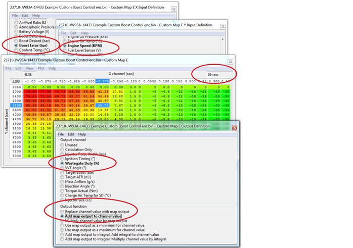
In this example above at 3200rpm and -0.375bar boost error (so under the boost target) Map E will ADD a value of 26 to the current WG Duty therefore increasing the WG Duty.
Assuming the current value for Map A to be 65 then the WG duty will increase to 91 (65 + 26) to give a final WG Duty of 91%.
As the boost (MRP) increases and nears the boost target then the size of proportional value added will decrease accordingly and as the Boost Target is achieved the proportional amount added will be zero.
If the boost overshoots the target boost value then Map E will REMOVE WG Duty as well.
NOTE: The Proportional value (output of map A) is a one time only added addition and it does not accumulate like an Integral value will do.
Calibrating the Proportional Custom Map
We suggest that the proportional and integral maps are not enabled until Map A for base WG Duty has been profiled and is fairly close for good tight boost control.
We then suggest you create an overboost condition and then enable the proportional and integral maps in other modes to see the individual results.
The following sequence is great for producing an accurate proportional or integral map.
Ensure Map A is accurately calibrated so it delivers the correct boost pressure for a given target boost pressure then simply ADD minus -0.20bar to the X axis as shown below.
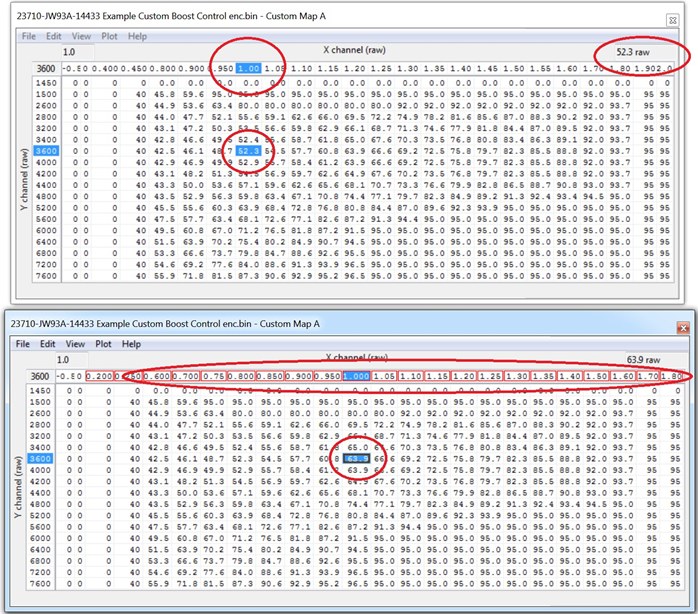
So now the column for 1.2bar becomes 1.0bar and WG Duty increases from 52% to 64%. When you select 1.0bar with RRBC you will get 1.2bar and you can see how the Proportional control deals with the overshoot, log the INTERIM and RESULT of Custom Map E to see the proportional component working.
If the boost reduces from 1.2bar to 1.1bar then you have to increase the proportional values for a 0.1bar boost error so the boost can be reduced further.
If the boost reduces from 1.2bar down to 0.9bar then you have to reduce the proportional values in Map E for a 0.1bar boost error.
We suggest you double or halve the values in Map E to increase or reduce the boost accordingly. The proportional addition should correct the boost instantly and there should be no over or undershoot if the proportional values are correct.
In fact the output of Map E (Map A WG duty plus Map E Proportional WG Duty component) should be the actual the WG duty value shown in Map A before you rescaled the X axis.
Further on from this if you have not rescaled Map A X axis then the output of Map E shows the values you should enter into Map A at a given RPM if the boost error is zero(as Map E has corrected the WG Duty to produce the Target Boost pressure you have demanded).
This method can soon populate an accurate proportional map suitable for the size of your turbocharger.
Once your proportional map is calibrated then turn off Map E and enable Map F to calibrate Integral map in the same way.
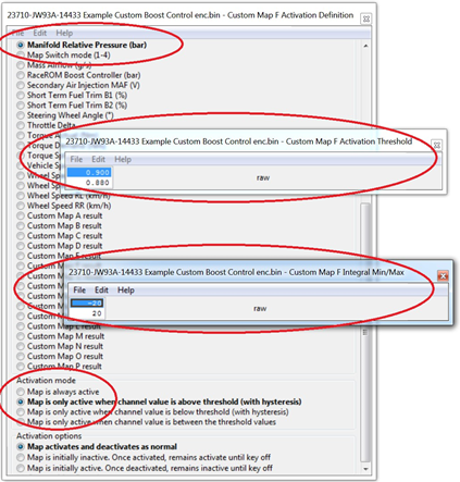
Custom Map F - Wastegate Duty Integral Control
- X axis is the current Boost Error (Bar)
- Y axis is Engine Speed (RPM)
- Map values are Wastegate Duty Integral compensation factor.
In the example shown below the X axis is boost error (the difference between the Target Boost and Manifold Relative Pressure MRP). The Y axis is Engine Speed.
Custom Map F output value will be added the current WG Duty but as an integral, so the value will keep increasing over a period of time (several times a second).
The proportional value (output of Map E) will also be added if the proportional map has been enabled.
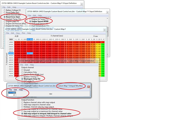
In this example at 3600rpm and -0.3bar boost error (so under the boost target) Map F will ADD a value of 0.06 to the current WG Duty (Map A plus Map E) therefore increasing the WG Duty. Assuming the current value for Map A to be 65 and Map E to be 26 then the WG duty will increase from 91% to 91.06% (65 + 26 + 0.06).
But as the Output Definition is ‘Add map output to Integral, Add Integral to Channel’ then this 0.06 value will quickly increment on each calculation therefore causing the WG Duty to rise quickly over a time period for a continuous boost error.
If the boost pressure overshoots the Target Boost value then Map F Integral component will also REMOVE WG Duty.
If the rate of change (Increment or decrement) is too fast then halve the values and retest. If the rate of change is too slow then double the values and retest.
The Integral Min/Max has been set so it can only add or subtract a maximum value of 20, this prevents the Integral from drastically changing the WG duty over a time period like during spool and part throttle conditions.
To further improve the boost control logic the Integral control (Map F) has been configured with an Activation Definition.
As shown below the Integral control (Map F) is only allowed to work when the MRP is over 0.9bar and it will stop working below
0.88bar. So the Integral control can only adjust the WG Duty on full load. This will prevent the Integral from ramping up (or down) the WG Duty at part throttle conditions.
Calibrating the Integral Custom Map
The Integral will not correct the boost instantly like the proportional map does, the Integral takes times and you will see the boost reduce (or increase) over a time period (0.1 to 2 seconds). If the Integral takes too long to correct the boost pressure then double the values in Map F so the WG Duty reduces more quickly.
If the WG Duty redcues too quickly and the boost begins to oscillate then halve the values until the boost is more stable and then fine tune.
We cannot adjust the frequency of the integral addition but doubling or halving the values will have the same affect.
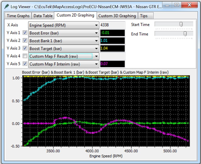
Below you can see an integral addition in action past 3500rpm when the activation pressure of 0.9bar was exceeded.
You can see the purple integral value (Map F Interim) constantly adjusting the WG Duty to maintain a zero Boost Error.
Our example screen shots and example ROM files have the proportional and integral values calibrated for stock turbo’s, larger turbo’s and stronger actuators will need smaller values in the maps (in theory).
Additional Boost Control calibration
Other compensation factors can also be created, some examples below.
- Target boost pressure compensation for Coolant and Air temperature
- Per Gear Target Boost and WG Duty compensation
- Air Temp and Atmospheric pressure compensation
Note these compensations should be applied before any Proportional and Integral maps are implemented (so created as Map B, Map C or Map D)
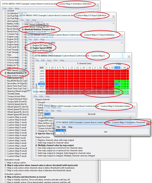
Custom Maps Boost Limit
In addition a custom map can be used as a boost limit, this is useful if the boost is over 1.7bar and only 1 x 4bar map sensor is fitted in the plenum (Inlet Manifold) or a Speed Density kit is used where the charge air sensor is built into the MAP sensor but a 4bar sensor is not available. If the pre throttle map sensor sensors are NOT changed then they cannot read over 1.73bar and therefore cannot be used for an overboost fuel cut protection.
In this case set the Boost Limit (RaceROM) map to 1.9bar or greater so this limiter can never be reached (as standard MAP sensors can only read to 1.73bar) then we can configure a Custom Map as a boost Limit like shown below.
The X axis is MRP from the Plenum MAP sensor, the Y axis is RPM the output will multiply the Injector Size by 1 or 0. Note the X axis at 1.8bar will multiply the Injector size by 1 so will NOT change the Injector open time but at 1.81 will multiply the Injector size by zero which will cut the Injectors.
The activation for Custom Map G is set at 1.75 bar so the fuel cut cannot happen below this pressure but the resume is set to 1.1bar before the Injectors will restore, the timer activation is set at 1 second so quick spikes will not result in a fuel cut.
How to set up Custom Maps Boost Control over 1.73bar
The Boost Error calculation is made using the pre throttle MAP sensors. If the pre throttle map sensors are still stock then they cannot calculate the boost error correctly over 1.73 bar (as 1.73 bar is the maximum they can read).
This becomes a problem when the Plug and Play Speed Density MAP sensor containing a charge air temperature sensor is used and a 4bar MAP sensor cannot be fitted.
The answer is to use a custom map to calculate the boost error by comparing the RaceROM
Boost Controller (RRBC) Target Boost and Manifold Relative Pressure (MRP) like shown below.
9.5.1. Custom Map B - Calculating Boost Error
The difference between the Target RRBC value and the current Boost MRP is the boost error and this is stored as the Custom Map B Output. In the example screen shots shown below the RRBC target is 0.8bar but the MRP is actually 1.2bar so an overboost of 0.4bar (Custom Map B output)
- X axis is the RaceROM Boost Controller input (Bar)
- Y axis is Manifold Relative Pressure (Bar)
- Map values are Boost Error amount (Bar)
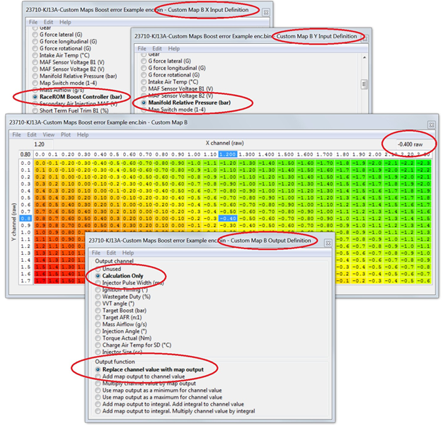
You can now use this Custom Map B boost error value as an input to the proportional or integral Wastegate duty maps like Map E or F on the previous Custom Maps Boost Control examples.
In this example we have set Custom Map C as a proportional map and in this situation Custom Map B Result of 0.4bar overboost would ADD -25% to the Wastegate Duty (so reduce the WG Duty by 25%).
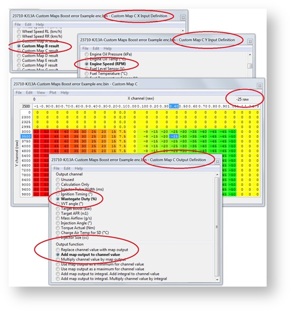
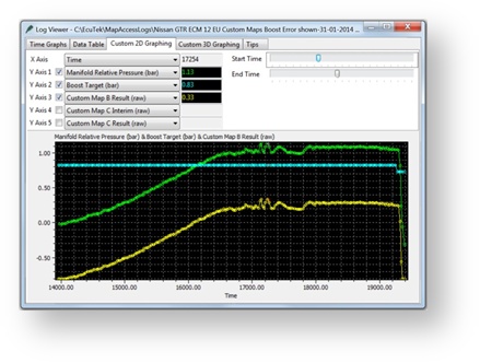
You can see from the example log file screen shot that follows the RRBC target is 0.83bar (CYAN Line) but the current MRP is 1.13bar (GREEN Line) and the Custom Map B result shows the current boost error (YELLOW line).
If you want to keep the same Custom Maps Boost Control example as shown previously (How to set up Custom Maps Boost Control) then make the following changes to the maps A, E and F.
- Map A: change Desired Boost to RaceROM Boost Control as the X axis Input
- Map E: change the X axis Boost Error input to the Output of Custom Map B
- Map F: change the Y axis Boost Error input to the Output of Custom Map B
In addition add Custom Map B as a new map so it can calculate Boost Error using the plenum based 4bar map sensor.
Note the pre throttle map sensors cannot and should not be removed as a DTC will occur and the ECU will enter SAFE Mode , in addition the WG Duty will drop to 0%. If the Boost Sensor DTCs are disabled then the ECU will still be in safe mode so we advise that you leave them connected at all time.
Still necessary?
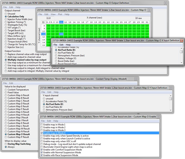
Custom Map MFD Custom Data display
You can set up a custom maps to output certain values on the MFD digital coolant temp gauge. These logging parameters can be displayed during the map switching mode or can be configured to display a value permanently.
This feature has to be used with caution and understanding and should be used occasionally and not continuously as other modules on the vehicle will receive an incorrect coolant temp.
The example below shows how to set up for AFR Display in Map Switch Mode 4
The X and Y axis are the AFR Bank 1 logging parameter input.
The Output of Map O is a calculation only and changes nothing.
The output value is multiplied by 10 so 12.5 (AFR) would be 125.
The Coolant Temp Display setting for Mode 4 is configured to show the result of Map O ALWAYS. So when mode 4 is selected then the Digital Coolant Gauge will show AFR
You can also show Ethanol Fuel Content, Fuel Trim, Knock Correction, Ignition Timing but you need to consider the units that can be shown by the Coolant Gauge (no decimal points and Centigrade)
EcuTek ProECU tuning tools tools should only be used by experienced tuners who understand the product and engine calibration.
If you do not fully understand this product then you WILL damage your engine, ECU or your vehicle.
Please ensure you fully read all EcuTek manuals BEFORE attempting to use ProECU with your laptop or your vehicle.
Use with extreme caution and understanding at all times, if in doubt then do not proceed.
EcuTek accepts no responsibility for any damage to the engine, ECU or any part of the vehicle that results directly or indirectly from using the product.
** If you are in any doubt that you do NOT have the experienced required to use this product then you should NOT USE IT **
Retail customers
** If you have any doubt that you do NOT have the experienced required to use this product then you should NOT USE IT, you should simply contact your EcuTek Master Tuner shown clearly on the top of your Programming Kit or visit your preferred tuning shop to have a professional tuner to use it for you **