SkyactivG Tuning Guide ND Miata
- Brandyn Mowat
- Chris Todd
- Lucan Hetherington
- Michael Howard

SkyactivG Tuning Guide (ND Miata)
Introduction
The Skyactive engine platform found in the ND MX-5 vehicles is a particularly complex system. Throughout our development we’ve made an effort to balance our efforts in simplifying the tuning system, as well as offering RaceROM features in the limited free space available to us in the ROM. This means our RaceROM offerings are slightly different than in other platforms as there are either simplified forms being used, or something altogether unique.
With a framework for the platform in place, we’ll be working with our dealers in order to balance the features for this platform, with the practical limits of the ECU.
Supplemental Content
Platform Specific
General
Table of Contents
The Platform
The Mazda Mx-5 SkyactivG cars use a high compression (14.0:1) 1.8L or 2.0L 4 cylinder engine utilising direct injection with a high degree of freedom of cam timing on both inlet and exhaust cams. This allows the engine to use many complex strategies to deliver high power and high efficiency for such a small capacity. The control system components are as below.
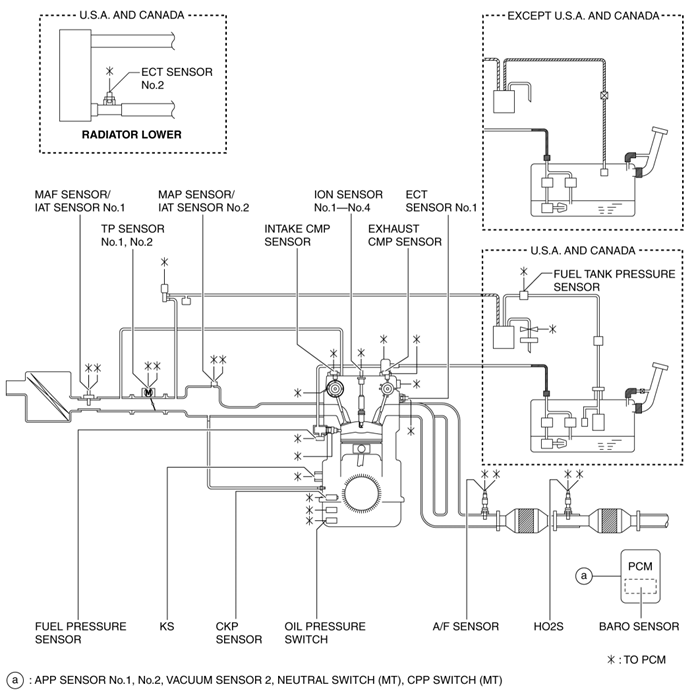
Mazda have employed ion sensing technology to model per cylinder detonation, pre ignition and air fuel ratio and uses these in many of the airflow and ignition timing strategies to preserve reliability while maintaining a high as possible performance and low emissions.
Ion sensing involves measuring the electrical current flow after the spark initially bridges the gap between the center electrode of the sparkplug and the ground strap. In the event of a misfire, no current flow can be easily detected, making it a fairly stable and accurate method of measuring misfires.
The 4-2-1 type exhaust pipes have been adopted for the exhaust manifold to create an engine with a high compression ratio.
Two types of load and airflow estimation have been adopted for the intake air amount measurement to achieve stable combustion free from abnormal combustion.
- L-jetronic (The intake air amount is directly detected by measuring the amount of intake air flow using the MAF sensor.) MAF sensor adopted
- D-jetronic (The intake air amount is detected indirectly by measuring the intake manifold pressure (pressure between downstream of the throttle valve and intake manifold) using the MAP sensor.) MAP sensor adopted
- IAT sensor No.1 and No.2 adopted
To improve the fuel economy and emission performance, an electric variable valve timing control has been adopted for the intake side, and a hydraulic variable valve timing control for the exhaust side. The electric type is adopted for the intake side to achieve expanded valve overlap and delayed closing of the intake valve (enlarged intake valve opening angle). The Hydraulic Lash Adjuster (HLA) has been adopted to achieve the maintenance-free valve clearance.
- Intake side: Electric variable valve timing control with independent CMP sensor
- Electric variable valve timing motor/driver
- Electric variable valve timing relay
- Exhaust side: Hydraulic variable valve timing control with independent CMP sensor
Engine hydraulic pressure switching control (using Engine oil solenoid valve) has been adopted to reduce the oil pump operation load on the engine.
To improve engine reliability, an ion sensor has been adopted which detects pre-ignition.
Some other features Mazda have listed as advances with their SkyActiv technology are.
Sliding resistance reduction
- Rocker arm (with built-in needle roller bearing) adopted for cam-contact area
- Reduced valve spring load
- Narrowed down crankshaft journal
- Optimized piston skirt shape
- Lowered piston ring tension
- Lowered drive belt tension
- Suppressed chain tensioner load by stabilized timing chain behaviour
- Oil shower pipe adopted
Mechanical resistance loss reduction
- Optimized oil passage
- Optimized oil pump shape
- Engine oil control adopted
Cooling loss reduction in early stage of combustion
- Piston cavity adopted
Pumping loss reduction
- Variable valve timing mechanism adopted on both intake and exhaust sides for fine control of exhaust amount and internal EGR volume
Cooling efficiency improvement
- Air seal cowl and flaps adopted
- Optimized cooling fan shape
- Optimized engine coolant passage
- Optimized water pump impeller shape
Combustion efficiency improvement
- Multiple hole-type fuel injectors
- High-pressure fuel pump
Accelerator / Throttle Control
Throttle control in the ND is heavily linked to torque demand. For a more thorough investigation of how torque requests and accelerator control are linked check out our article Skyactive G - Driver Demand Acceleration Request
Throttle Limiting Map
This can be used on turbo cars specifically to prevent WOT at low pedal, as the ecu tries to get the airflow while the turbo is spooling, and then having a big throttle fluctuation as the throttle closes to regulate the airflow to the desired levels. It's nice when it works (Ford Ecoboost) but we don't have the maps to tune the response of the OEM strategy so use the limiter map.
Map List
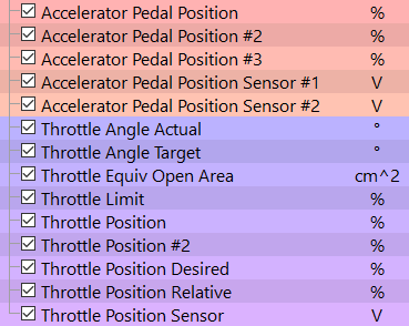
Live Data Parameters
- Accelerator Pedal Position (%)
- Accelerator PPedal Position #2 (%)
- Accelerator Pedal Position #3 (%)
- Accelerator Pedal Position Sensor #1 (V)
- Accelerator Pedal Position Sensor #2 (V)
- Throttle Angle Actual (Degrees)
- Throttle Angle Target (Degrees)
- Throttle Equiv Open Area (cm^2)
- Throttle Limit (%)
- Throttle Position (%)
- Throttle Position #2 (%)
- Throttle Position Desired (%)
- Throttle Position Relative (%)
- Throttle Position Sensor (%)
Throttle Limit 
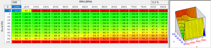
Sometimes the cruise control functions are limited by the throttle limit map as well so the map may need to be profiled differently than expected in order to allow the CC to work correctly (As Shown).
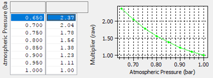
Throttle Limit Multiplier
Offers the ability to adjust the throttle limit profile as atmospheric pressure reduces.
Eff Open Area Multiplier for PR
Divisor of desired effective open area based on manifold pressure ratio, this should not need to be modified if the throttle has not been changed.
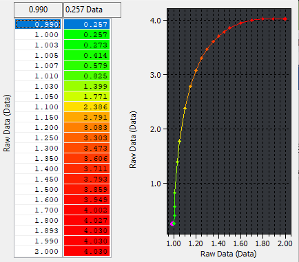
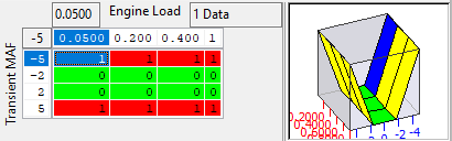
MAF Desired Transient Blend
Blend map to change how MAF transients are applied to desired MAF. Reduce the value to zero at moderate to high loads to help stop oscillating desired MAF and throttle. This can be especially useful in cars with MAFs near a supercharger inlet or in bad flow regions.
Throttle Effective Open Area
Desired effective open area used in conjunction with the Throttle vs Desired Area map. These two maps drive into each other with correction on each loop. It is complex and they shouldn’t need adjusting to keep the throttle open.

Throttle Vs Desired Area

Throttle Target Limits 2d & 3d
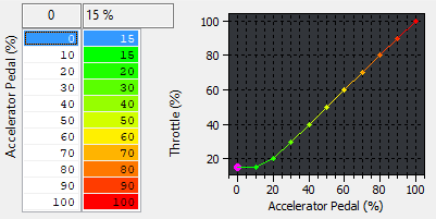
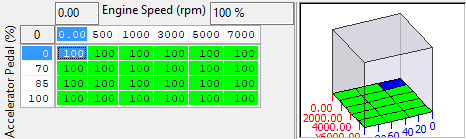
These two OEM throttle limiters are used as well as the RaceROM limiters. Ideally these can be left stock and the RaceROM table is used instead.
Camshaft Timing
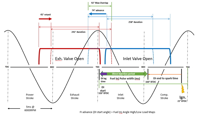
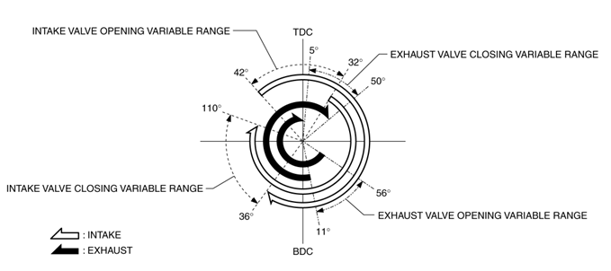
Mazda utilise an electronic Intake Cam VVT actuator to allow quick and precise wide range of movement. With a maximum overlap from intake open to exhaust close is 92° allowing for huge amounts of blow through if not correctly calibrated. In addition to using the cam timing for EGR duties, it allows the system to enact the “Mazda Miller Cycle at low loads. This cycle allows the intake valve to stay open beyond the bottom of the travel and into the compression stroke causing a slight amount of the air fuel mixture to go back into the intake manifold during the initial ~20% of the piston’s compression stroke. The benefit being a slight reduction of the effective compression ratio. They also utilise a hydraulic exhaust cam VVT actuator to allow for maximised. The basic outline of the cams and how it related to crank angle and injection period is shown below.
They allow a wide range of movement (roughly 74deg), where the target position in the map is the advance or retard from the base stop position. The VVT has different target modes, for idle, cold start and normal operating temperature and the switch point between the modes is not known yet.
| Item | Specification | |||
|---|---|---|---|---|
| Valve Timing | IN | Open | (°) | BTDC 420ATDC 32 |
| Close | (°) | ABDC 36-ABDC 110 | ||
| EX | Open | (°) | BBDC 56-BBDC 11 | |
| Close | (°) | ATDC 5-ATDC 50 | ||
Correcting for effects of VVT
In early testing it was found that VVT Intake cam angle has a profound effect on the VE of the engine, especially with the ND's very wide range of operation (74° crank angle). So it has been necessary to make some provision for this as the ND can on occasion transition between cam maps, or (seeming) reduce the cam advance to effect torque output or avoid detonation.
This function is still in development and will include additional maps for exhaust VVT and expand on the MAP weighting map. However it is quite useable in it's current form.
Intake Cam VE Correction
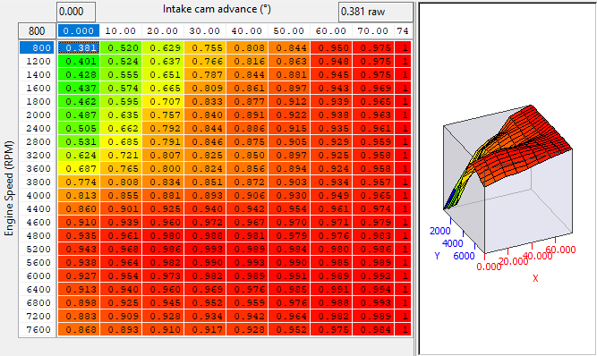
This map is a simple multiplier that is applied to the output of the Speed Density Volumetric Efficiency map.
There is no live data to specifically support this map, however when back calculating "SD VE Calculated" from the MAF sensor, the effects of the cam correction maps are taken into account. So in reasonably steady state conditions "SD VE Calculated" follow "SD VE Estimated" quite closely when properly tuned.
Intake Cam Correction Weighting
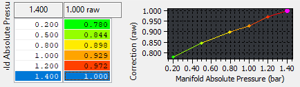
This effectively adjusts the effects of the "Intake Cam VE Correction" map based on Manifold Absolute Pressure, if the values in this map are lowered it has the effect of "flattening" the Cam VE Correction map, where this map returns 1.0 the Intake Cam VE Correction map is used as is, the result is as follows:
CamCorrectionFinal = 1 - ((1 - CamCorrectionMultiplier) * CamCorrectionWeighting)
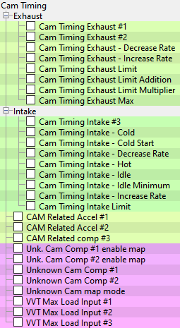
Map List
Live Data Parameters
- VVT Intake Actual - Actual intake variable valve timing control - Advance amount from max retard position °(deg)
- VVT Intake Desired - Target intake variable valve timing control - Advance amount from max retard position °(deg)
- VVT Exhaust Desired - Target exhaust variable valve timing control - Retard amount from max advance position °(deg)
- VVT Exhaust Actual - Actual exhaust variable valve timing control - Retard amount from max advance position °(deg)
Cam Timing Exhaust #1 & 2 (hot/cold)
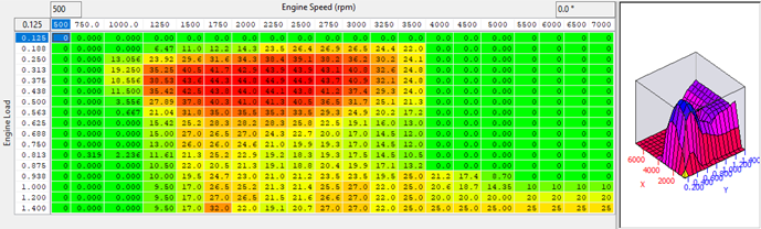
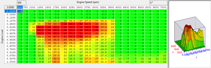
These are standard maps that set a desired exhaust cam angle for different speeds and loads. The output values are the amount of retard from the base position (most advanced angle 56deg BBDC). Maps one and two are believed to be high and low temperature, testing can be done on the dyno to see which one is used when.
It is believed that the large amount retard used at low loads on the exhaust cam is used to promote Exhaust gas recirculation through the manifold. When back pressure is significantly different due to higher airflow or exhaust blockages (like turbocharger turbines) significant changes may be required to these maps. Especially as the load values with force induction will be exceeded even at low pedal % and engine speeds.
In the EcuTek Turbo charged Forced Induction example ROM the load axis was rescaled to allow it to compensate for the higher cylinder fill appropriately and more retard was used at higher RPM and loads to try get more out of the power stroke. The tuned profile looks like Below, testing should be done to confirm that the vehicle you are tuning responds in the same way.
Cam Timing Intake - Hot / Cold
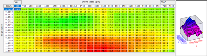
These maps set the target intake cam angle. Mazda have calibrated them to match the exhaust cam mapping and create the Mazda Miller Cycle
When forced induction is involved the profile of these maps will need to be altered significantly as the available airflow characteristics are vastly different. Tuning these maps for forced induction requires load axis changes and significant modification to the higher RPM and load cells, deceasing intake advance at lower RPM high loads and increasing the advance at high RPM high and low loads.
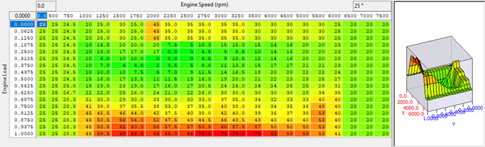
Cam Timing Intake Idle
The intake cam angle target at idle. This may need to get adjusted if the idle blow through is higher than expected and causing issues.
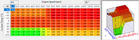
Cam Timing Intake Idle Minimum
At different atmospheric pressure more intake cam advance may be required, and minimums can be set here.
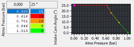
Cam Timing Intake Limit
At low RPMs the cam timing is limited likely to prevent excessive blow through and overlap. These values should not need to be changed.
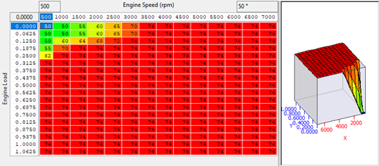
Cam Timing Intake / Exhaust Increase and Decrease Rates
There are increase and decrease rates for both cams, but these should not require adjustment.

VVT Max Load Input #1 - 3 (Cold to Hot)
The intake and exhaust cams have a load limit applied to them based on engine speed and intake air temperature. It is assumed that this was employed to try to reduce the likely hoot of knock by reducing the VE at high cylinder charge temperatures.
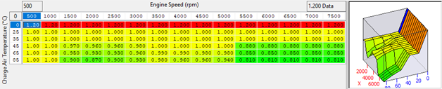
When FI is employed the load limits applied by these maps must be raised to allow the cams to access he correct regions of the map and use the correct cam timing. In the EcuTek FI example ROM these have been raised from 1.0 to 1.4 to match the load axis input in the Cam angle maps at normal AIT’s.

Fuelling
Fuel Target Tuning
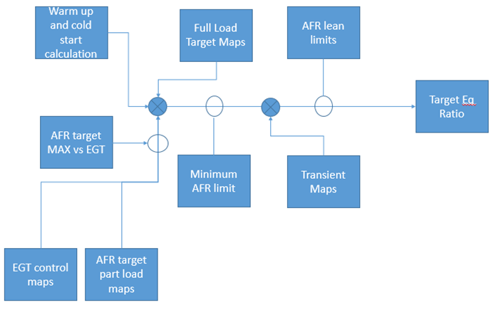
The Target Fuelling strategy for ND is complex and is based on engine load with many protection modes and temperature control methods. It is basically split into 3 primary modes start up, part load, full load temperature control as well as two different fuel cut modes with corrections and limits are applied at various points in the calculation. There are fundamental differences between NASP and FI tuning that particular attention should be paid, such as accel pedal and temperature thresholds. These are covered later in the document.
Mazda split the fuelling Control Method into zones
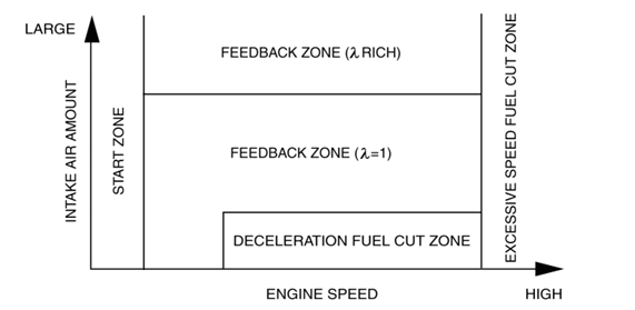
While cylinder fill models and lambda targets derive the injection quantity the conversion and correction of the injector open time is restricted according to the above modes.
Start Zone = RPM < 500
In this mode the injection time is set according to engine coolant temperature (low engine coolant temperature = long injection time). After start corrections are also set for a specified time according to engine coolant temperature directly after engine start
- Low engine coolant temperature = large correction
- Low intake air temperature = large correction
Feedback zone (λ = 1) = All other times
In this mode injection time is calculated as a base amount using Cylinder fill and fuel flow coefficients. It also applies corrections for
- Warm up enrichment (low ECT or AIT) after start
- Short term fuel trims (AFR Error actual to target)
- Rear O2 sensor
- Warm up enrichment at high loads
- Long Term Fuel Trims (Learned value based on average value of A/F deviation amount)
Feedback zone (λ rich) = WOP accel and EGT above threshold
- Short term fuel trims (AFR Error actual to target)
- Warm up enrichment at high loads
- Long Term Fuel Trims (Learned value based on average value of A/F deviation amount)
- EGT Corrections (Based on the accelerator pedal opening angle or on engine speed and cylinder fill.)
Fuel cuts are determined as Injection time = 0 during
- Excessive speed fuel cut zone = Above Rev Limit
- Deceleration fuel cut zone = Accel pedal closed, above decel fuel cut off (DCFO) RPM and Vehicle speed
A heavily Simplified view of the strategy is below
AFR Target
Our advice for fuel tuning is use the trims as your guide. Adjust your MAF/SD maps as you need to keep the trims to zero and you will be sorted.
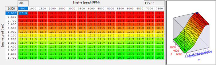
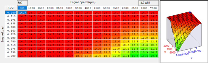
This is an AFR target table that is employed when the WOP (Wide Open Pedal) threshold is exceeded. In the OEM strategy there are 2x 2d maps (AFR Target - Full Load #1 / #2) the result of which is overwritten by the output of this map.
It is only enabled by checking the box in "AFR Target Override Enable"
Typical usage will include lowering the WOP threshold to a level that corresponds to a value that gives loads in the region of 0.8 or more. This is primarily for turbo application and used to switch to a richer target AFR that is variable with load, and prevent Lambda 1 at part pedal but significant load due to boost. On our turbo ND we lowered the WOP threshold from 93% to 35% but you should test for your selves.
The WOP thresholds can be found in the Fuelling->Accel Thresholds

Part Load Fuel target
From our testing the ND generally runs Lambda 1 at part throttle, except when in the transient mode (a fraction of a second) and when the catalyst temperature is above the cat temperature threshold map EGT control #2, it then richens up to the 3d part load tables. It may also use the maps at part throttle (maybe at full throttle without kickdown button pressed on auto car).
The part load fuel targets are the maps “AFR Target Part Load #1 (#2 and #3)” affect the target AFR the ECU will ramp down to the target value (CAT temp goes about 826°C) so you can lean these out to reduce enrichment when at part/full throttle.
WOT AFR target
The WOT closed loop throttle is well understood but very complex. The AFR target at WOT is controlled by the 2 2d maps, along with some very small offsets for load. However, the ECU is constantly monitoring catalyst temp, exhaust temp and presumably cylinder head temp, all it appears through modelling. It will always ramp towards the richest target when certain cat temp thresholds are met or exceeded.
You can make the car run the WOT target you want by zeroing out the 3d EGT control enable table, or one of the 2d correction tables. I'm also sure that if you don't change the 3d target AFR tables that there is another temp threshold that will cause the afr target to ramp towards the values in those 3d maps.
So, to properly control the AFR at WOT you will need to alter the 2d maps, the 3d part load maps, the EGT/CatT thresholds and/or the CatT control enable maps. I will need to check what thresholds do what when I get back into the office.
You NEED to do some testing at part throttle, it generally runs Lambda 1 at part throttle once out of the transient mode (a fraction of a second) and it then richens up to the 3d part load tables, but only once the cat temp has reach 826.84degC CatT. If you put lean AFRs in those tables to make the CatT uncontrollable it will then wait until 900degC before making the target richer again using the same tables to avoid high cat temp at WOT.
On WOT, the ECU will use the 2d maps. Unless it runs into "something" it doesn't like, then it will use a number of richer maps, and if you don't edit them, you will get rich AFR on WOT. There are maps that provide a different target like the 3d maps *that are not normally used at WOT* and there are also 2 other 2d maps that are used depending on the cat temp and other factors, plus a load of other compensations that sometimes get applied.
Temperature Control fueling
There is a comprehensive temperature control strategy employed in ND and we have defined several maps that will richen the target for high catalyst, uego or estimated exhaust flange temp. These maps are in the Fuelling->EGT Control category.
The "EGT Control - Enrichment Enable" map will change how much enrichment gets applied by outputting a multiplier.
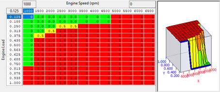
Typically back to back runs will bring the cat temps up and the ECU tries to fight this with richer AFR, so you may want to keep this in place for the end tune sent out for customers but disable for testing.
As previously discussed when not running stoich because the CAT temperature is high the part load tables are used. It is believed that these are still used at full throttle so would recommend to change the values at high RPM and load.
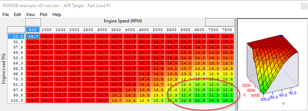
If part load maps target AFRs are excessively lean and make the Catalyst temperature uncontrollable the RGT control strategy will then wait until EGT Control #4 is reached (OEM is 900degC) before making the target richer again using the AFR target MAX vs EGT tables to avoid high cat temp (does the same at WOT).
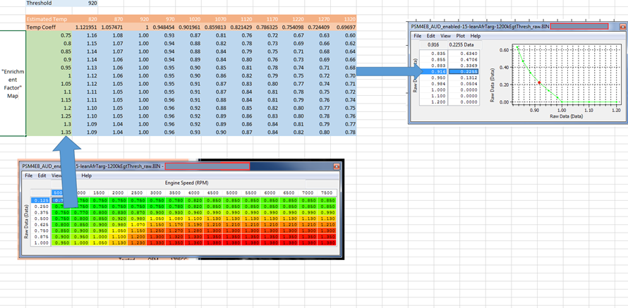
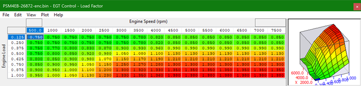
If you put 0.5 in this map the final AFR target would be the average of your normal map value (from the 2d WOT tables for example) and the values in the right hand column of the AFR Target _EGT Control Map. If you fill this table with 0 there will be no high temp enrichment from this strategy. The 3d "part load" AFR target tables are not used unless the temperature goes above 827deg, but that doesn't stop them from also being used at WOT at high cat/egt temp.
You can see from that map that one of the values used in the calculation is the 920 degrees and that if the temp is below this the AFR target is still 14.7 which is a maximum, so it would still allow 12.5 target.
Then that final enrichment is weighted by this map:
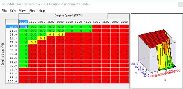
When this strategy is active you need to look at the AFR Target - EGT Control map, the numbers in the left column are an EGT target correction factor, and if you raise them for a given AFR you will see less enrichment, if you lower them you will see more enrichments. The output of this is used instead of or on top of the Part load maps so changing these might lower the target AFR as well (though not the way its shown here the changes here are to prevent it going rich at high loads).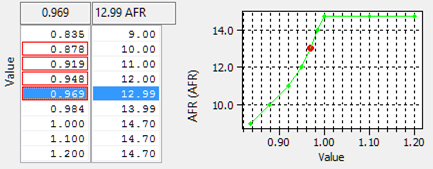
Appropriate EGT and Catalyst temperature control
It is recommended to alter the Selected minimum AFR targets as opposed to the EGT thresholds, if you change the EGT thresholds #2 #4 and #5 by a small amount (say 50°C) to raise or lower the temperatures when the enrichment maps for EGT control are used the risk of catalyst cooling strategies may not give adequate temperature reduction in time, this is more risky as using the above methods you can maintain a leaner AFR until the catalyst temp gets very high and then target a much richer AFR.
Transient Fueling
It does appear that the transient maps are essentially an accel pump, If you need to make it last longer or put more fuel in you should first try increasing the AFR Target – Transient Enrichment, which appears to be a global multiplier. The axis is likely delta throttle however currently unknown
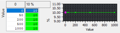
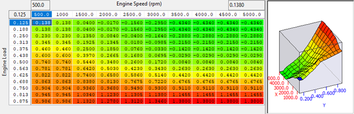
If you need to try enrichening or enleaning a particular load or RPM point adjusting the AFR Target Compensation for load maps #1 & #2 is the next step, its believed these are a % correction value to the FR correction amount.
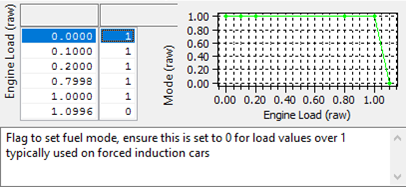
Injection Mode (RaceROM)
The injection mode maps are involved in the desired engine load calculation and should not need to be changed.
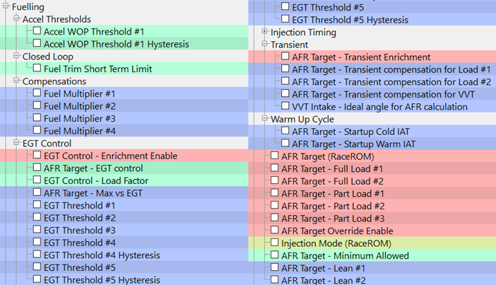
Map List
Live Data Parameters
- AFR Actual
- AFR Target
- Fuel Mode Open/Closed loop
- Fuel Rail Pressure Absolute
- Fuel Trim Long Term
- Fuel Trim Short Term
- Injection Quantity
Injection Timing
Injection timing on the MX5 ND is crucial to proper performance, when the boundaries are pushed the injectors appear to be the first part of the system that is flow restricted. To combat this injection times, quantities and pressures can be altered to deliver more fuel in the same window without running into piston impingement or lean pockets preventing proper combustion initiation.
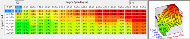
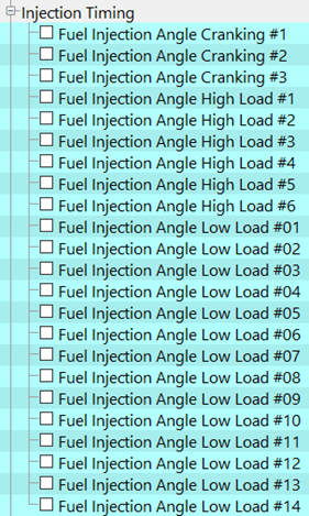
The injection angle maps have been added but each running mode has not yet been discovered, if you need to make changes to prevent misfires the suggestion is to increase all of the high load ports of each of the numbers of maps.
Injection angle High/Low Load #1-14
To set the injection angle adjust the map, usually only high load high RPM cells need to be adjusted, and as the output values appear to be in crank angle from TDC outputs above 360° may be injecting well into valve overlap.
Map List
Fuel Pressure Control
The Mazda ND has low and high pressure Fuel Pump and rail system set up as per the diagram below, it’s a fairly standard set up using a return less low pressure system with a pressure regulator in the tank (4.5bar base control pressure not manifold referenced).
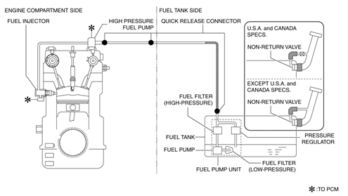
The low pressure side is a common design style and feeds the high pressure fuel pump directly. The high pressure Pump works from the exhaust cam on a 4 lobe pump drive with solenoid spill control.
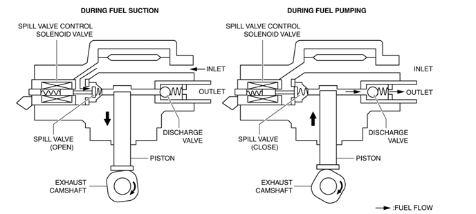
Fuel pressure is derived by the reciprocation of the piston made by the cam installed on the rear end of the exhaust camshaft. Based on the control signal from the ECU, the spill valve control solenoid valve opens and closes in the high pressure fuel pump at a desired angle, the drive currents would use a similar peak and hold style output but this is not covered in any maps or documents currently..
If the spill valve control solenoid valve malfunctions and the fuel pressure exceeds the specified value, the relief valve opens to assure safety.
High Pressure Fuel Pump Pressure Target
The High Pressure Fuel Pump (HPFP) has man different operating modes which are not yet understood, There are definitely different target for cranking and after start that are implemented to attempt to improve atomisation when cold. There are fuel pressure logging parameters that can be used to monitor the achieved pressure and the target is set by the Pressure target 1-5.
Fuel Pressure – Target #1 - #5
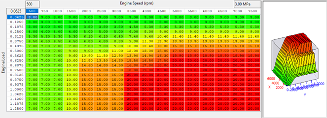
These should be increased to improve the fueling capacity or if experiencing misfires due to injection quantity or piston crown fuel impingement. They are engine load and speed dependant and care must be taken that the relief valve set pressure is not exceeded as valve wear will occur very quickly and cause pump malfunction.
Idle
The Skyactive cars use the electronic throttle ignition angle and cams for idle control there are many complex idle control. The also attempt to balance the airflow demand using torque calculations so accurate frictional torque and combustion efficiencies help with stable idle.
Typically the issues that occur are involved with forced induction and return to idle stall or idle oscillation/hunting with accessories switching on/off. While the root cause of the oscillations are not known there are some suggestions on how to combat the idle surge and the overrun recovery.
Idle Hunt can be caused by improper torque estimation, bad airflow estimation and hence torque demand or swapping from idle ignition control to normal running mode.
- The first thing to try is to make sure that the idle speed when it raises that it doesn’t not go onto the main ignition timing maps, try lowering the main timing maps (knock limited VVT on) to the same amount that is maintaining the equivalent RPM at idle.
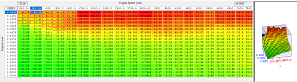
- The torque demand maps can also be adjusted to stabilise the idle and improve the overrun RPM drop issue.
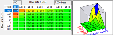
- The target idle compensation maps can be raised as in some ROMs this has helped.
Map List
Live Data Parameters
- Engine Coolant Temperature
- Engine Speed
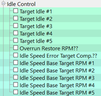
Target Idle #1-5
Idle speed target maps used in unknown modes.
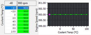
Idle Speed Base Target RPM #1-5
Idle speed target maps used in unknown modes.

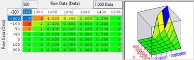
Idle Speed Error Target Comp
Adjust this map if the overrun stall behavior is an issue.
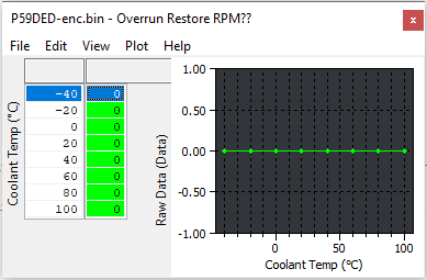
Overrun Restore RPM
It is believed that this map is the fuel injector cut restore point, however in which mode it is used is not known.
Ignition
Regarding the ignition control, please look at the example ROM. The reason the alternate maps control the ignition is because they have lower values, and it always chooses the lowest. You will notice that the Knock Limited map is lower at higher loads then the Base map, the offset is applied full time we suspect to assist in things like CAT temp emissions or engine condition etc.
For most vehicles, the best way to tune the ignition would be to use the knock limited map and keep an eye on the timing value to make sure that even at light load the timing is not too high. What will happen is that when you increase or decrease the knock limited map it will use the lower value (between base and alternate) but if there is no knock it will feed timing back in up to the base (plus offset) value. If you want more timing add it to the knock limited map until it uses the base then add to the base as well.
So if you want to run 1 map, (we chose the base map in the example ROM for the added resolution), you need to ensure that you zero the corresponding offset map, apply those offsets to the base map, then copy all the values from the Alternate maps that are otherwise lower than the base maps. If you then add 10deg to the Alternate map you will always be on the base map. At this time we have not yet determined how KCS Learning impacts these maps.
EcuTek’s advice is that you should only tune the "Knock Limited" maps for higher load, and the "MBT offset maps" if you want to adjust very light load timing. Do not adjust the base maps, as these are Maximum Best Timing (MBT) maps and employed in the torque calculations that form the basis of many of the things the ECU is calculating. Things that influence the MBT timing are doing just that, and not really critical to tuning on load for forced induction. You need to concentrate on the "Knock Limited" maps.
Similar to other platforms the ND MX-5 runs off the lowest of the MBT (+ offset) or knock limited maps. There is no need to run more than MBT and you can't run more than the knock limited ignition, however, be aware that these maps will have no doubt been calibrated for a specific octane level, and the ECU provides the facility to pull the timing up or down depending on what it thinks the overall knock/octane situation is (simplification of course).
Due to the many things that are pulling the timing up and down it's normal to find your final timing values not agreeing with map values, as the map values really are just the starting point, however making relative adjustments to the "alternate" maps definitely shows up as changes in the final value.
We know the car runs in a variety of injection modes and are fairly sure that these involve changes in ignition, possible significant changes but without a little more live data to back up what we're are seeing it's hard to determine what's going on. This will no doubt be an area of further research.
| Control Zone | Control Condition | Ignition Method |
|---|---|---|
| Start Zone | Engine speed is less than 500rpm | Engine Starting |
| Normal Zone | Engine operation except start zone | Cycle estimated ignition (Determines ignition timing adding each correction to basic spark advance |
Ignition timing method table A: Ignition timing Base, B: Correction for ignition timing
| Contents | Calculation Method or Determination for Ignition Timing, Spark Advance and Correction | Control Zone | ||
|---|---|---|---|---|
| Start Zone | Normal Zone | |||
| Starting Ignition | Determination based on engine coolant temperature | A | ||
| Cycle Estimated Ignition | Basic Spark Advance | Set value according to engine speed and charging efficiency | A | |
| Correction | Engine Coolant Temperature Spark Advance Correction | Ensures combustion stability when coolant temperature is low. According to engine coolant temperature High Charging Efficiency, Low Engine Coolant Temperature = Large Correction | B | |
| Intake Air Temperature Correction | Suppresses knocking when engine intake air temperature is high. According to engine intake air temperature and engine coolant temperature High engine intake air temperature, high engine coolant temperature = Large Correction | B | ||
| Warm-Up Promotion Spark Retard Correction | Activates catalytic converter earlier. Maximum 50s after engine start Engine coolant temperature = Correction | B | ||
| Torque Reduction Correction | Reduction of shift shock, traction control, or suppression of vehicle vibration. Based on torque reduction request from TCM or DSC Large reduction request = Large Correction | B | ||
| Knocking Spark Retard Correction | Knocking Suppression Acceleration when charging efficency volume increases (acceleration amount) is given value or higher. Large acceleration amount = large correction | B | ||
| Valve Timing Correction | Ensures combustion stability. When phase difference changes due to electric variable valve timing control wand hydraulic variable valve timing control. Correction according to change in phase difference | B | ||
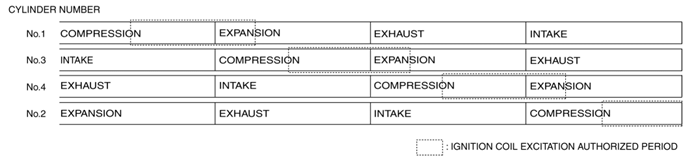
The ECU energizes the ignition coils according to the ignition timing calculated from the engine operation conditions and the igniter energization time. The igniter energization time (ignition coil energization time) is determined according to battery voltage and engine speed.
Map List
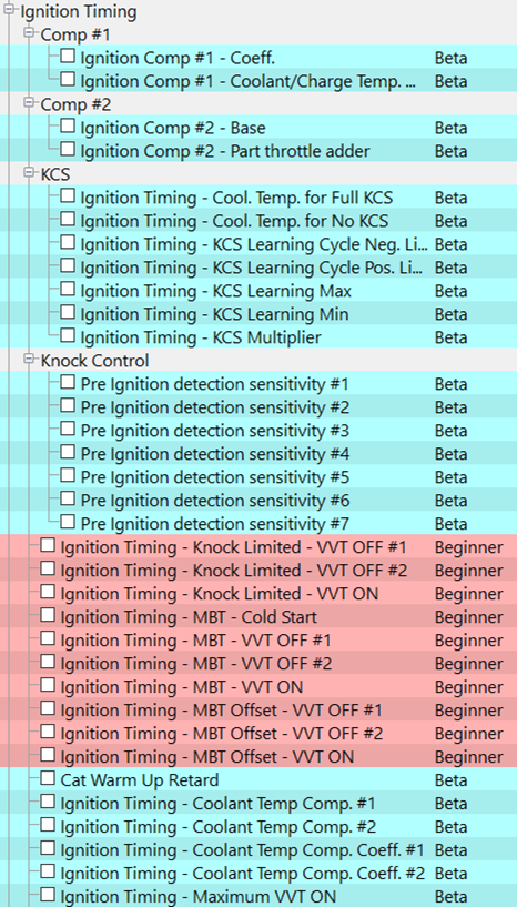
Live Data Parameters
• Ignition Timing (°) – Current actual ignition timing in degrees BTDC, negative means ATDC
• KCS Learning Value (°) – learnt ignition addition to knock limit maps based of knock sensor activity
• Knock Correction (°) – Offset due to knock, negative is retard.
Ignition Timing 0 MBT VVT ON/OFF#1/OFF#2
When the correct condition is active to use this map (VT ON / OFF or cold start) this is the MBT Ignition timing. Base ignition value will be lowest of either the (MBT Timing + MBT Offset) or the Knock Limited Timing.
Knock Limited Values will be subject to KCS correction. This map is used for torque calculations as well by comparing it to the current ignition timing and calculating the % less torque.
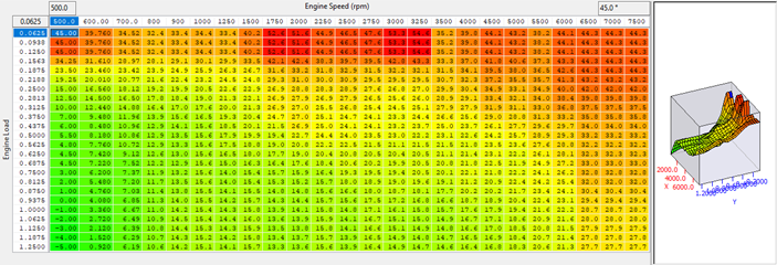
Ignition Timing - MBT Offset - VVT ON/VVT OFF #1, #2
Offset from MBT timing to alter the base desired timing value, used when MBT is not most desirable timing, typically at light load.

Cat Warm Up Retard
The ignition timing applied when in catalyst warm up mode. Set this to a reasonable value to stop the ignition retard being applied during start up and eliminating any rough running on catless race cars.
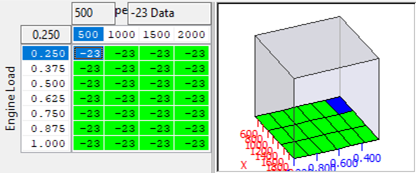
Ignition Timing - Max VVT ON
Maximum absolute timing value that can be achieved when the VVT is active, this value will need to be lifted for FI cars with high octane fuels. The load axis is conservative and expected loads will be roughly double this on most FI cars.
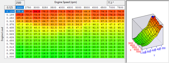
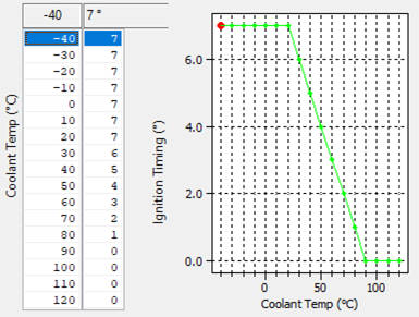
Ignition TIming Coolant Temp Comp #1
This map is the base amount of timing added to other compensation values and then added to the final timing value from the MBT + Offset maps, limits are applied after this addition and the final value is compared to the Knock limited calculation output and the lowest value chosen. This map is multiplied by the Ignition Timing - Coolant Temp Comp. Coeff #1 map.
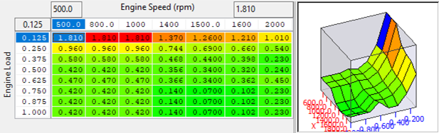
Ignition TIming - Coolant Temp Comp Coeff #1
This map multiplies the output of Ignition timing – Coolant Temp Comp #1 depending on the current load and RPM. The value is then added to the MBT maps for final selection.
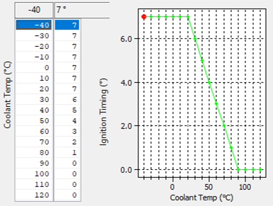
Ignition Timing - Coolant Temp Comp #2
This map is the base amount of timing added to other compensation values and then added to the final timing value from the MBT + Offset maps, limits are applied after this addition and the final value is compared to the Knock limited calculation output and the lowest value chosen. This map is multiplied by the Ignition Timing - Coolant Temp Comp. Coeff #2 map.
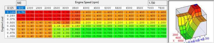
Ignition Timing - Coolant Temp Comp Coeff #2
This map multiplies the output of Ignition timing – Coolant Temp Comp #2 depending on the current load and RPM. The value is then added to the MBT maps for final selection.

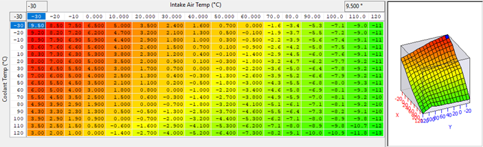
Ignition Comp #1 - Coeff.
This map multiplies the output of the Ignition Comp #1 – Coolant / Charge Temp Map giving an adjustment to the knock limited map output based on charge and coolant temperature. This map can be adjusted to increase the effect of charge temperature ignition timing reductions for different loads.
Ignition Comp #1 - Coolant / Charge Temp Map
This map gives a value to the Ignition Comp #1 – Coeff. The values can be positive or negative and form the basis of the load / RPM correction.
Ignition Comp #2 - Base
This map outputs a base value that is multiplied by Ignition Comp #2 – Part Throttle adder this can be adjust if you a seeing larger amounts of retard at part throttle when using the knock limited maps.
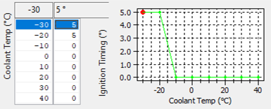
Ignition Comp #2 - Part Throttle Adder
This map multiplies the output of Ignition Comp #2 – Base depending on the load and RPM.
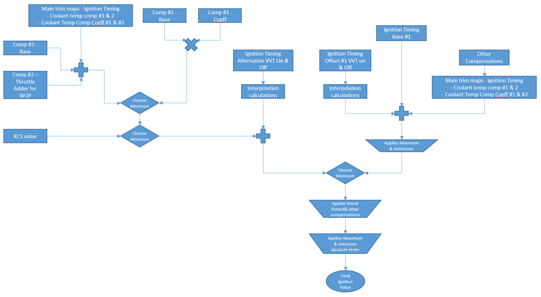
Our current understanding is that these maps are not used all of the time they are employed when the car is running on the alternate ignition maps full time and that the KCS retard value is not lower than the AIT CLT temperature retard amount so it uses this retard. You may also be able to get it to do this if you add a lot of AIT / CLT retard values so that when the temp gets up the total sum is less that the normal ignition map values, however, this may not work as there may be some unknowns limits or applied to the value before it chooses which ignition value to use.
Knock Correction (KCS)
The knock control and ion sensing systems in the ECU are designed to detect engine knocking condition (pre-ignition) due to the high compression ratio and also to monitor the combustion condition in the cylinder during combustion. It does this by measuring the ion current generated during combustion as an electric current by applying voltage to the spark plug and amplifying it in the ion current detection circuit integrated in the ignition coil, the diagram below illustrates the process
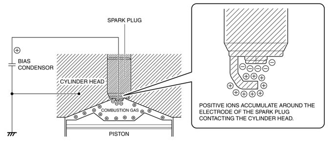
After the spark plug discharges, voltage is applied to the centre electrode and ion current generated inside the cylinder from the beginning to the completion of a combustion is detected. Because the ion current is a very small, it is amplified in the ion detection circuit and sent to the ECU for processing.
The generated ion current varies depending on the actual combustion process and varies similar to the combustion/pressure inside the cylinder. The ECU determines an abnormal condition if ion current is generated outside of the during a normal combustion window. The ECU can then make adjustments to timing and effective compression ratio to try eliminate the pre ignition or knock issue.
If the engine is running off the knock limited maps, but isn't experiencing knock, the ECU has the facility to increase the ignition advance. From our experience the OEM strategies are very good at picking up detonation, so don’t be put off by letting it have some authority to advance the ignition. In much the same way as the BRZ has "advance" maps that it can use to increase the base map timing (Subaru work on the basis that MBT timing is base timing + full advance timing).
What is currently not well defined (due to limited live data) is the difference between short and long term correction and how that gets applied or stored. If you monitor the KCS value I think you will see an idea of relative learned knock correction, and the knock retard is the final value including learnt and instant retard.
The final KCS retard value is compared to the other addition coefficients as per the previous ignition timing diagram and the lowest of either is then added to the knock limited timing amount.
Map List
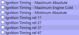
Ignition TIming - Coolant Temp for Full KCS
Initialisation temperature for full KCS addition

Ignition TIming Coolant Temp for No KCS
Minimum temperature for KCS Activation

Ignition TIming - KCS Learning Cycle Neg. Limit
Maximum allowed KCS retard limit in degrees

Ignition Timing - KCS Learning Cycle Pos. Limit
Maximum allowed advance limit of KCS value in degrees

Ignition Timing - KCS Learning Max
Maximum advance step value for KCS learning.

Ignition Timing - KCS Learning Min
Maximum retard step value for KCS learning

Ignition Timing - KCS Multiplier
Multiplier for the current KCS retard/advance amount depending on engine load and RPM. The output of this calculation and learning function is then compared to the other correction amount and if smaller, added to the knock limited map increasing the timing up to the MBT limit, otherwise the other correction coefficient maps are used.
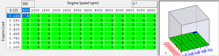
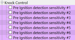
Pre-Ignition Detection Sensitivity
This may likely be an ion current amount however the actual values and logging are not available as yet.
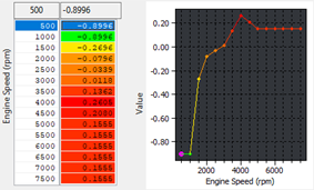
Limiters
Map List
Live Data Parameters
- Vehicle Speed
- Engine Speed
Rev Limit
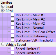
The rev limits on MX5 ND are complex and the exact purpose or function of each of the limiter are currently unknown all of the rev limit maps will need to be lifted. Raising the rev limit maps does not change the shift limits of the TCM so in automatic cars the rev limit may not be hit as the gear shift occurs before the rev limit is hit.

Speed Limiter 1 & 2
Raise the speed limits to allow a faster maximum vehicle speed, both maps should be raised by the same amount.

Load
Airflow
The ND ECU is multi-talented when it comes to measuring airflow, and the MAF sensor is just one tool at its disposal. It does have its own SD strategy, but you absolutely will not be able to tune the OEM strategy! The OEM SD uses a polynomial equation which takes in map, tps, atmo, vvti and rpm along with many 2d coefficient maps to calculate the airflow, we don’t lay this out because as a tuner you will have no frame of reference to know how to alter the coefficients.
Typically OEMs model their engines and generate the coefficients to begin with and then fine tune them after automated dyno testing to generate clouds of data points which get turned into more accurate coefficients. So our SD is much more simple, and no doubt falls short of the OEM version in some of the extremes of inputs or for very brief periods of time when the OEM maths will compensate for some unique behaviour. But push the boost up to 0.4 bar and all those carefully generated OEM coefficients generate are no longer useful!
We also believe that it uses other calculation functions like ION sensing and EGO content to measure actual AFR in cylinder and derives an air flow amount from this value (because it knows how much fuel it injected). Also valve angle and manifold pressure can be used to model the airflow, the list and function of all of these is not currently known. All of these calculated airflow values are then compared to each other and the MAF actual reading and weighting is applied to the plausibility of the MAF reading etc and a final airflow value is decided. These and the other reasons above are why a RaceROM strategy has been developed.
To combat this we have blended the MAF and MAP based airflow models (in a map) so it will use the method that we know is most reliable at the desired operating parameters it running and the set a map up to use the OEM SD polynomial or our SDVE map to deliver the correct airflow amount. Blending is used as opposed to a multiplier as the calculations are so complex and inclusive that simply overwriting one does not give adequate results. The blend sequence is represented below.
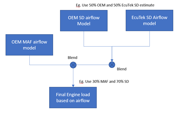
You would choose the blends based on what you think is running the care more accurately to give the correct fuelling.
It is possible to have speed density enabled and run using only the MAF sensor or a combination of MAF and OEM SD. it’s not necessarily needed for non-Forced Induction tunes but can be useful depending on the modifications.
SD Volumetric Efficiency
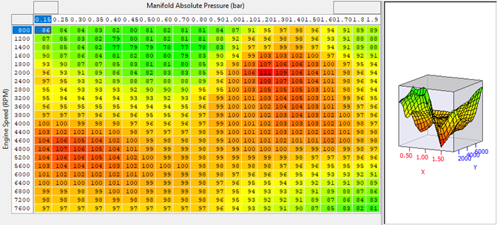
Everyone should be familiar with this type of map now, and it's use in ND RaceROM is as expected. However due to further corrections for cam angle they are subject to the overall multiplier that comes from the "Intake Cam VE Correction" and "Intake Cam Correction Multiplier".
Speed Density Enable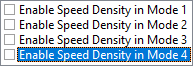
This is an overall enable for RaceROM speed density. However, as the SD strategy is used for overriding the OEM blending of airflow models, it is possible to have speed density enabled and run using only the MAF sensor or a combination of MAF and OEM SD. it’s not necessarily needed for non-Forced Induction tunes but can be useful depending on the modifications.
Speed Density SD Blend
This map returns a weighting factor that is used to blend RaceROM SD calculated load with that of the OEM SD strategy.
The final SD calculated load is composited in the following manner:
SDLoadFinal = (SDLoadRaceROM * Blend) + (SDLoadOEM * (1- Blend))
Experience has shown that the OEM SD strategy becomes extremely inaccurate once in positive boost (MAP over about 1.1) so the default values set it to use the RaceROM SD full time. In order to fully tune the RaceROM SD VE map this map will need to be set to 1.0 throughout.
This can be done in stages, but experience in development is that a well calibrated MAF will be easier to rely on, however it could be that the car runs well in all situations except positive boost, in which case it may be more straightforward to only worry about tuning the RaceROM SD VE map in positive boost.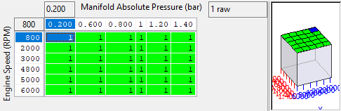
Speed Density SD/MAF Blend
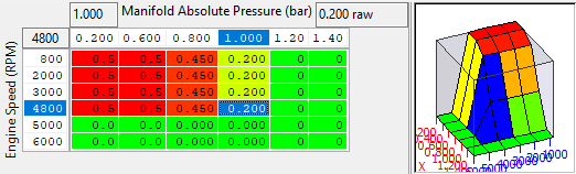
This map is a weighting factor for the MAF derived load vs SD derived load.
The final load is the composite of MAF/SD thus:
ChargeFinal = (ChargeMAF * Blend) + (ChargeSD * (1- Blend))
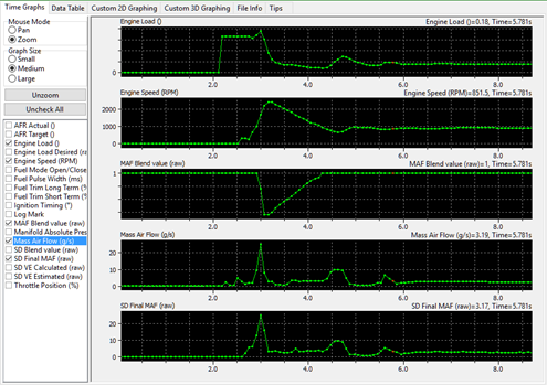
In simple terms the larger the output of this map the more MAF is used, values of 1 will result in only MAF being considered, values of 0 will result in only SD being considered.
When tuning SD one can start using a MAF blend map filled with 1 and check the MAF scaling, once properly scaled or if using OEM induction it's reasonable to decrease the MAF weighting and begin to tune the SD VE map (remember to set the SD blend map to 1.0 so you're running on RaceROM SD and not the OEM SD).
The MAF blend can be monitored in Live Data using the parameter "SD MAF Blend", the log image below shows the blend in action.
Desired Engine Load Limit
A new OEM value that is 1.2 by default. This should be raised to at least your anticipated max load. Typically this will be approximately the same as the MAP. However there are other things at play limiting the desired torque, and therefor load which we are still investigating.

Engine Load Limit
The limit of the actual developed load. This should be raised to above your anticipated load to allow the fueling and ignition timing to be set correctly.

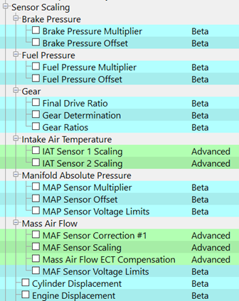
Sensor Scaling
Adjusting sensor scaling appears to behave similarly to other platforms in that you should scale the relevant voltage limits or scaling values in order to suit the new sensor.
Map List
Brake Pressure Multiplier & Offset
The brake pressure sensor scaling uses a multiplier and offset method of scaling. If the sensor has been changed you can calibrate the new sensor using these values.
Multiplier
 (MPa / V)
Offset
 (MPa)
(MPa)
Fuel Pressure Multiplier & Offset
The high pressure fuel rail contains a pressure sensor and can be rescaled using the common multiplier and offset method.
Multiplier
 (MPa / V)
Offset
 (MPa)
(MPa)
Gear
Gear ratios can be re scaled if changes have been made, this will correct wheel torque and acceleration values and also calculated vehicle speeds.
Final Drive Ratio
The final drive reduction ratio and is believed to include wheel size and diff ratio.

Gear Determination
Calculated current ratio used to determining the current gear.
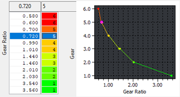
Gear Ratios
Adjust if ratio’s or gearboxes have been changed. The gears are in ascending order from the top with 1st at the top and 6th at the bottom.
Intake Air Temperature 1&2
There are two air temperature sensors in the SkyactivG MX5, one in the MAF housing (#1) and one in the manifold pressure sensor (#2) cars sensors. There is also an ambient air temperature sensor but it’s scaling is not available yet.
The data is volts per temperature and other IAT sensors, if installed will need to be calibrated correctly using a known device or the pull up resistor values measured on the ECU.
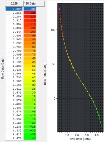
Manifold Absolute Pressure
MAP sensors scaling for SkyactivG cars is crucial you can set both the Multiplier and offset values (like most other platforms as well as the sensor voltage limits
Map Sensor Multiplier

Map Sensor Offset

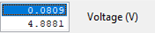
Map Sensor Voltage Limits
In this table the upper value is the minimum voltage for the MAP sensor, the bottom value is the maximum voltage.
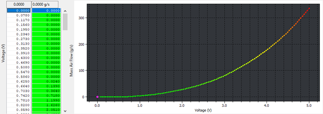
Mass Airflow
MAF sensors form the basis of the ND’s complex airmass estimation functions, correct MAF sensor scaling and physical placement is essential for good fueling and load estimation. The principles of MAF scaling are standard and care should be taken to keep the MAF scale realistic in the airflow amounts.
Maf Sensor Correction #1
This map should not need adjusting however may be useful with blow through SC cars to try correct certain voltages that give temperature dependent airflow variations.

MAF Sensor Scaling
Scale this map as you would any other vehicle, make sure that at the achieved voltage the airflow amount gives the desired AFR with no trims. MAF scaling analysers are available online from many open and closed sources.
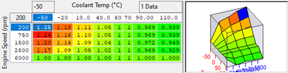
Mass Airflow ECT Compensation
Compensate for engine coolant temperature airflow deficiencies using this map, it should not need to be changed unless you are trying to correct an issue specific to airflow at set temperatures.
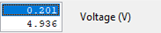
MAF Sensor Voltage Limits
These may need to be raised if you are exceeding MAF voltage saturation point (5.0V) or lowered with big MAFs an low air speeds. The top value is minimum voltage, and the bottom value is the maximum voltage.
Engine Displacements
If the engine displacements have changed, you should calibrate these values as they are used in engine load calculation and cylinder filling models.

Torque
The ND has a very complex torque control strategy and finding what works best for the vehicle and driver is necessary. It is believed that Mazda have adopted a strategy similar to Ford in that driver demands are converted to desired airmass and then compared to the actual airmass to find and actual torque and maintain that with timing, throttle and VVT angle. The driver demand is not measured in torque but a linear acceleration that is converted to a desired torque value and compensations for efficiency and losses applied.
The complexity of the system has induced us to implement an overwrite of the OEM system that forces it to use the neutral torque map instead of the normal driver demand maps. This map is based on accel pedal and RPM and is covered later in this section.
When forced induction is added to the NASP SkyactivG engine considerable adjustments are required the torque outputs of either the driver demand or other torque maps should be adapted to fit the expected torque.
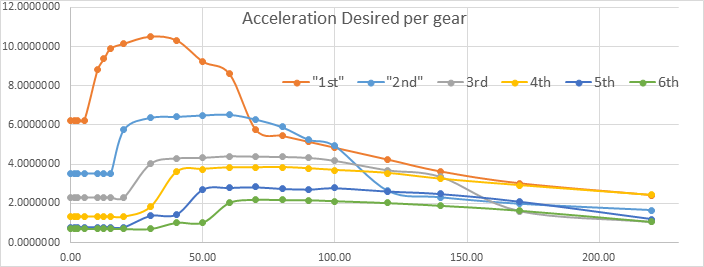
The Mazda strategy appears to use a linear acceleration value to set a driver torque set point we believe that Mazda did this as its allows very precise driver feel calibration, as this acceleration is the actual force felt when increasing the acceleration.
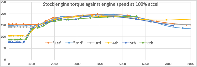
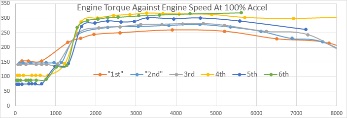
The linear acceleration maps use a vehicle speed and accel pedal position to set the desired acceleration in m/s2 this is then translated through the gear ratio, wheel size maps and with a list of corrections like aero drag into a desired engine torque. For a PSRXE0 ROM the calculated engine torque demand using the gear ratios etc and drag coefficients is about like below (as you can see it matches actual engine torque fairly well in Nm).
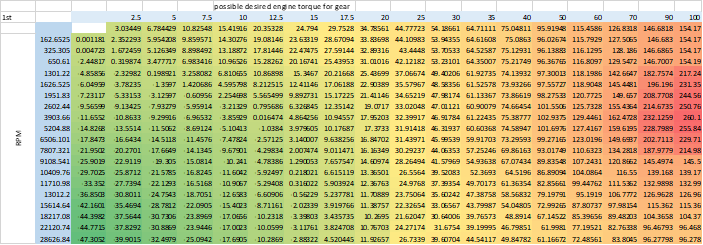
We have developed a spread sheet that can convert these linear acceleration values into torque and then back from a requested torque value into a linear acceleration value if you wish to retain the use of the stock torque demand method to try and improve drivability. If you want to use this sheet please contact Support@ecutek.com for a copy. To use the excel sheet to calculate the stock torque amount, then increase the stock torque amount to your desired amount and copy (CTRL + Alt + C & V) straight back into the driver demand maps.
You can short cut this though by simply increasing the driver demand maps by percentage to get the same result just a little rougher.
For a more thorough investigation of how torque requests and accelerator control are linked check out our article Skyactive G - Driver Demand Acceleration Request
Map List
Live Data Parameters
- Engine Load
- Engine Load Desired
- Accelerator Pedal Position
- Throttle Position
- Torque Actual
- Torque Desired
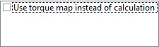
Torque Map Instead of Calculation
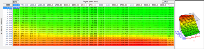
We have provided the ability to use the Torque Desired (Neutral) map instead of the driver demand to simplify the tuning, this may produce certain drivability issues however in certain modes (such as cruise control or overrun) however can be used to get good results.
Our torque demand hack uses the torque map employed in neutral, all of the time. If you want more airflow, demand more torque. DON'T remove the negative numbers at high RPM and low load as the throttle will hang open (overrun slows the car and has negative torque at the engine, i.e. engine braking). If you have issues with the throttle snapping open you will probably find a steep jump in the torque demand map.
Torque Desired Neutral
When the above map is selected (Torque Options) tune this map to set the desired engine torque in other calculated modes.
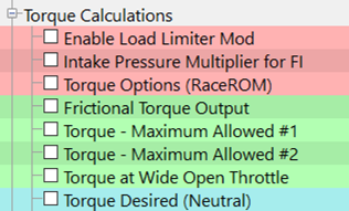
The Neutral Torque Demand map is still used (if enabled in RR) to drive the desired torque which will have an effect on VVT and ignition timing, as well as the base desired load values, you may need to balance the desired torque profile vs accel to get smooth throttle application. For supercharged cars with large amounts of parasitic losses at low RPM this may need to be changed significantly, looking at MAF and MAF desired logging parameters is the best way to tell if the torque demand requires changing.
Frictional Torque Output
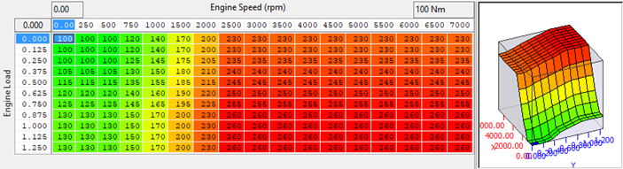
This map can also be used to increase the amount of assumed friction losses of the engine and could be used if you know the power usage of the type of supercharger used to get a better estimate of desired torque.

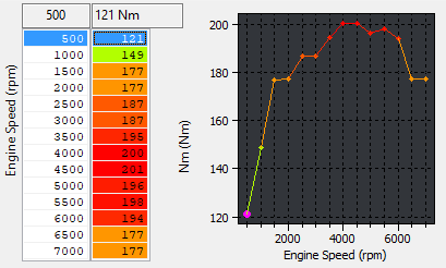
Torque - Maximum Allowed #1 & #2
These maps should be raised in order to allow the appropriate amount of desired and actual torque.
Torque at Wide Open Throttle
It provides a limit on the desired torque value found in the driver demands map. These maps should match the expected torque output of the engine.
Intake Pressure Multiplier for FI (Desired Load Multiplier)
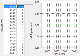
We have added the map shown below which can be found in the "Torque Calculations" category. It essentially scales the desired load at WOT, the short, easy explanation is you should probably aim to put values in this map a little (say about 0.2bar) above you anticipated boost at WOT to bring the desired load up in line with the desired torque (they are quite loosely linked it turns out).
With this in place changes to throttle calibration maps and thermal efficiency calculation tables are not needed to result in a fully open throttle at 100% accel.
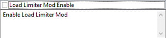
Enable Load Limiter Mod
In certain vehicles or ROMs at part throttle the desired engine load is not controlled effected by the desired load multiplier, If you experience some part load throttle oscillations or the desired load does not raise high enough and causes drivability issues try using the load limiter mod check box. If it doesn't effect the issue make sure to un-check it again and look at other options.
Misc.
Alternator Control
The MX5 ND has a smart alternator that in some case uses and i-Eloop system, Mazda i-ELOOP is a regenerative braking system. Using this, The vehicles transfer energy that is lost during braking to a specially designed alternator. This alternator takes these surges of energy and directs them to a capacitor. This capacitor charges in seconds and distributes the electricity to necessary systems and features of the vehicle. With these systems charged through the use of braking, this takes a lot of pressure off the alternator to leech power from the engine.
Therefore, the engine salvages a lot of fuel that would otherwise be used by the alternator, improving fuel economy generously in the process (Courtesy of Mazda https://www.marketplacemazda.com/blog/what-is-mazda-i-eloop-and-how-does-it-work/).
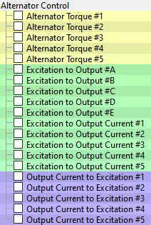
There are maps use to control and estimate the amount of torque used when charging the capacitor at different currents and these torques are included in torque demand and actual calculations. The complete function is not currently known however currents can be altered to achieve different torque at different speeds. These maps should not need to be altered.
To assure Idling stability, controls the generator output voltage to the optimum amount according to the engine operation and electrical load conditions.
The PCM determines the engine operation and electrical load conditions based on the input signals from each control part. It then uses this information to control the energization time of the generator field coils.
Determination method for target excitation current
- Calculates the target excitation current according to the generator target output amount and the generator rotation speed.
- The generator target output amount is calculated according to the target battery voltage and battery voltage.
- During deceleration fuel-cut, the ECU increases the generator output amount and stores electricity in the battery/capacitor. In conditions other than deceleration, only the required amount of electricity is charged according to the battery status to lower the load on the generator.
Determination method for field coil excitation time
- The ECU increases or decreases the field coil excitation current by sending a duty signal to the power transistor built into the generator.
- The field coil energization current changes according to changes in the power transistor excitation time. This is accomplished by changing the duty signal duty ratio. For example, when the battery positive voltage drops, the duty ratio of the duty signal sent to the power transistor is larger, increasing the field coil excitation current.
Map List
Live Data Parameters
- Alternator Duty
- Alternator Voltage Desired
- Alternator Voltage Output
- ECU Voltage
EcuTek ProECU tuning tools tools should only be used by experienced tuners who understand the product and engine calibration.
If you do not fully understand this product then you WILL damage your engine, ECU or your vehicle.
Please ensure you fully read all EcuTek manuals BEFORE attempting to use ProECU with your laptop or your vehicle.
Use with extreme caution and understanding at all times, if in doubt then do not proceed.
EcuTek accepts no responsibility for any damage to the engine, ECU or any part of the vehicle that results directly or indirectly from using the product.
** If you are in any doubt that you do NOT have the experienced required to use this product then you should NOT USE IT **
Retail customers
** If you have any doubt that you do NOT have the experienced required to use this product then you should NOT USE IT, you should simply contact your EcuTek Master Tuner shown clearly on the top of your Programming Kit or visit your preferred tuning shop to have a professional tuner to use it for you **