Nissan/Infiniti VR30DDTT Tuning Guide
- Brandyn Mowat
- Lucan Hetherington

Introduction
Nissan and Infiniti's latest venture into sports luxury vehicles has resulted in the release of the Nissan VR30DDTT powertrain, inspired by the VR38tt found in the R35. These vehicles sport some of the lastest features developed and come in two different configurations.
Already an award winning engine, the VR30 offers seamless power delivery, the latest in direct injection technology and a range of special equipment in order to easily monitor, maintain, and increase the power and torque delivery.
maps denoted with a RaceRom logo ![]() are tables from the RaceRom software and require the addition of that software.
are tables from the RaceRom software and require the addition of that software.
Engine Variants
Standard Output Engine
- 300 horsepower with 295 lb-ft of torque
- single cooling pumps
Shared Features
- Water to air intercoolers (With Aircon Cooling capacity)
- Twin Turbos boasting electronic wastegate actuators and an integrated manifold
- Aluminum block with arc sprayed mirror coating lining the cylinder bores
- Aluminum cylinder heads with integrated exhaust manifold
- Electronically controlled variable displacement oil pump
- Dual Variable Valve Timing VTC (Electronic inlet cam. Hydraulic Exhaust Cam)
- Direct Injection
High Output Engine
400 horsepower and 350 lb-ft of torque
- Turbo Speed Sensors
- dual cooling pumps
Summary of Software
The software to cover the VR30DDTT engine has been introduced to allow reprogramming of the factory ECU in order to tune the necessary components of the calibration in order to allow for modifications and increases in power. This is not a standalone repalcement ECU so you shouldn't run into the associated issues or disadvantages of setting up a purpose-built ECU and control system from scratch.
The software allows easy control over most factory parameters including:
- Boost Targets and wastegate control
- Target AFR
- Ignition Timing
- Fuel Delivery including fuel pump calibration (using the same style pump as OEM)
- Airflow Measurement and fuel compensation
It also allows the addition of extra features to improve the speed and quality of the tune. These are features such as
- Safeguards for temperatures and airflow that the factory calibration does not include
- Valet Modes
- EcuTek ECU Connect compatibility and adjustment
- Map switching for fuel and ignition timing
As the product progresses and development occurs, new features and improved definitions will be added.
Block Programming
Method of Operation
Block Programming (BP) will be enabled after a RaceRom patch is installed on an ECM. This means the first time you program with a BP/RaceRom equipped ROM the ECU needs to use the slow OEM programming sequence and therefore programming time will not change. On subsequent programming operations, BP will be used. The minimum programming time is approximately 20 seconds and BP will always reprogram the start and end block. More changes will require more blocks to be reprogrammed taking additional time. DTC clearing and power-off sequences still need to be followed after programming.
Failed Flash Recovery
Block Programming (BP) will be enabled after a RaceRom patch is installed on an ECM. This means the first time you program with a BP/RaceRom equipped ROM the ECU needs to use the slow OEM programming sequence and therefore programming time will not change. On subsequent programming operations, BP will be used. The minimum programming time is approximately 20 seconds and BP will always reprogram the start and end block. More changes will require more blocks to be reprogrammed taking additional time. DTC clearing and power-off sequences still need to be followed after programming.
- Close the ProECU Programming Window
- Disconnect the battery for at least 15 seconds to stop the programming code continuing to run in RAM
- Manually select the correct ECM programming window for the car. This is a critical step as ProECU will not be able to auto-detect a partially programmed ECM
- Select the correct ROM
- Program
Tuning Guide
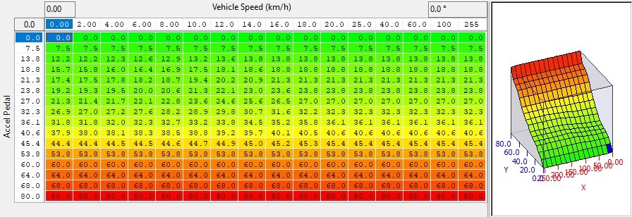
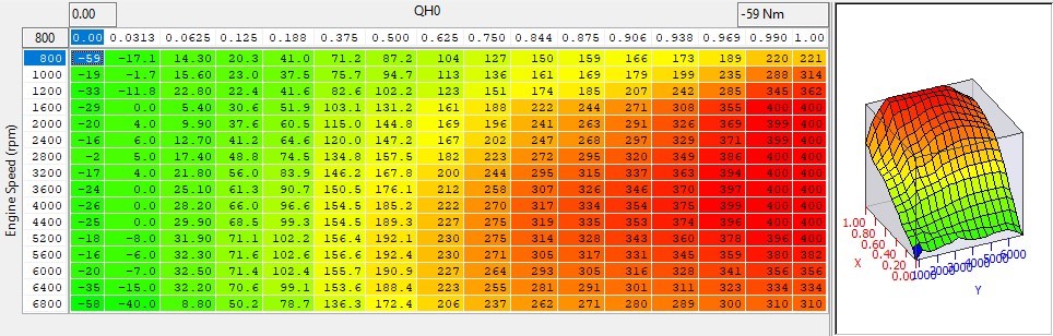
Accelerator Pedal
Although the VR30 has very complex learning and control strategies (and in some vehicles force feedback pedal control) the accelerator to throttle response is only basically defined. It does, however, give adequate recalibration of the OEM pedal characteristics.
Live Data Parameters
- Accelerator Sensor #1 - Default accelerator logging parameter for accelerator pedal voltage
- Accelerator Sensor #2 - Secondary accelerator pedal sensor logging parameter for pedal voltage
- QH0 - Percentage of throttle airflow requested. (While not specifically related to the accelerator pedal it is relevant)
Map List
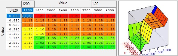
These maps can be changed in order to give a more linear pedal response. While it varies vehicle to vehicle, they are generally more linear at lower speeds but gradually loose sensitivity at higher speed.
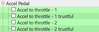
The trustful table must be set to the same values as the main table in order to avoid a DTC (P0605)
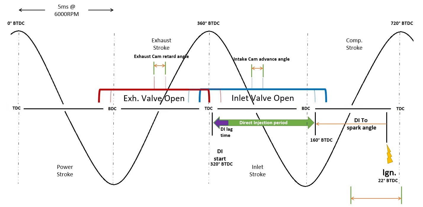
Camshaft Timing
Introduction
The VR30 has variable cam timing on both the inlet and exhaust cams allow for very precise valve opening and closing events and modulation for EGR etc. The Intake cam advance is driven electronically, and the exhaust cam timing is altered hydraulically by engine oil pressure. Cam timing can be adjusted in the calibration to get more power through the midrange and top end.
Map List
Live Data Parameters
- VTC Exhaust Duty B1 (%) – Bank 1 Exhaust VVT Oil control valve duty in %.
- VTC Exhaust Duty B2 (%) – Bank 2 Exhaust VVT Oil control valve duty in %.
- VVT Exhaust Angle B1 (°CA) – Exhaust cam angle for bank 1 in crank degrees
- VVT Exhaust Angle B2 (°CA) – Exhaust cam angle for bank 2 in crank degrees
- VVT Intake Angle B1 (°CA) – Bank 1 Intake Cam angle in crank degrees
- VVT Intake Angle B2 (°CA) – Bank 2 Intake Cam angle in crank degrees
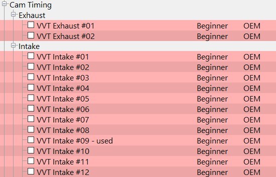
Exhaust Cam Timing
There are a series of maps which are utilized in different conditions. At the time of wiriting, we are unsure of the conditions under which each map is used, particularly since, as standard, there are few differences. As such we speculate that if changes are made on one, it may help to change the others.
These maps represent the target exhaust cam retard angle in crank degrees which we believe to be marked from the centre point of the cam.
Intake Cam Timing
There are a series of maps (0-12) which are used in different conditions. At the time of writing, we believe map 09 to be used primarily but are unsure of the conditions under which the other maps are used. As standard, there is little difference to the maps so if changes are made on one, it may help to change the others.
These maps represent the target intake cam advance angle in crank degrees from cam centre as the reference point.
Boost Control
For more in-depth information, check out VR30DDTT Boost Control
Starting with RaceROM Version 3, the OEM boost control has been rewritten and replaced with our own simplified boost control strategy using its own set of dedicated RaceROM maps. Upon adding a version 3 or later RRFF, this option is enabled by default, and comes pre-populated with a sensible stage 1 boost control setup. As the VR30 utilises electronic wastegates it is possible to set WG position at any RPM, the principles (proportional, integral and derivative) are the same as a pneumatic wastegate, however the control is performed in position rather than duty. There are also turbo speed sensors in the 400hp (high boost pressure) model which adds another dimension to the amount of control the ECU can exert. There are no blow off valves (BOV) as standard equipment on the VR30DDTT motors and as a result they are susceptible to pre-throttle over-boost during gearshifts or when entering overrun. We have added some functionality to the boost control system in order to reduce the over boost amount, fortunately the system additionally is able to control MAP is relatively well using the throttle, further reducing the risk to engine internals. 
Map List
Live Data Parameters
- Boost Bank1/Boost Bank2 – Absolute pressure in bar, measured by the two boost sensors
- RBC Maximum Desired Boost – Relative boost max target matches number format on the gauge
- Boost Target – Absolute pressure target in bar, measured by the intake manifold pressure sensor Boost Error – Difference between MAP and Boost Target, positive numbers are over boost
- Boost Target – RBC Maximum – The current RR boost controller setpoint.
- Boost Target Multiplier – The QH0 based multiplier used for boost target correction
- Manifold Gauge Pressure – “Boost” pressure measured in bar above the current atmospheric pressure
- Manifold Absolute Pressure – Absolute pressure in bar, measured by the intake manifold pressure sensor
- Manifold Pressure Sensor – MAP sensor voltage value
- Turbo Speed B1 & B2– Current turbo speed in rpm only available on the 400hp models
- Wastegate Actuator Position B1 & B2 – The mm distance the wastegate has extended (related to WG angle)
- WG Actuator Position Sensor B1 & B2 – the WG position sensors current voltage output
- WG Corr Base – The output from Wastegate Posn. Corr. Calculation, not used in RR boost control strategy
- WG Corr Integral – WG duty added by Integral correction of EcuTek boost control strategy
- WG Corr Proportional – WG duty added by Proportional correction of EcuTek boost control strategy
- WG Corr - Prop Int Sum – Correction resulting from proportional and integral added together
- WG Corr – Transient – Derivative component of boost error calculation
- WG Offset – During Gearshift – Offset applied in mm during upshift.
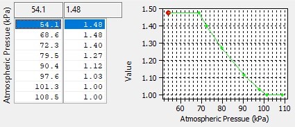
- WG Target – Air Temp Comp – Air temp correction value from target map (in Bar)
- WG Target – Atmospheric Pressure Correction amount applied from the Atmo Pressure Comp map
- WG target – Basemap Lookup - the value referenced in the WG target map (in mm)
- WG Target – Position – Final Position target after all corrections (in mm)
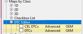
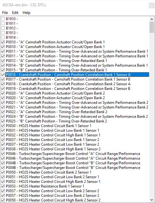
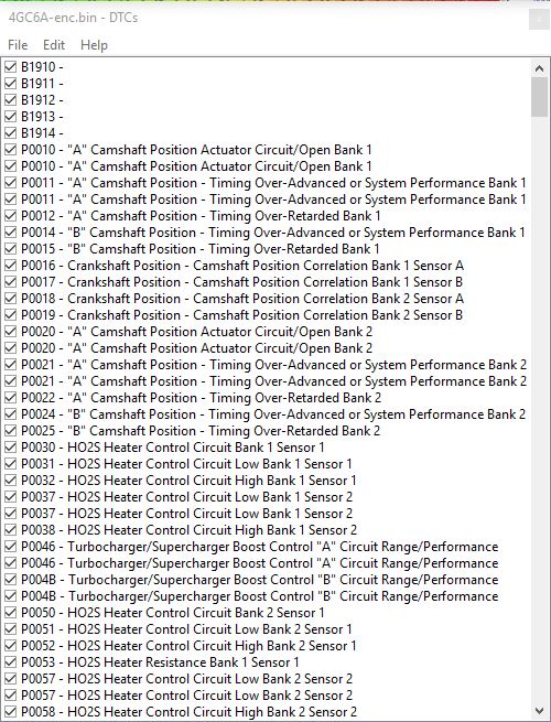
Diagnostic Trouble Codes
All OBD vehicles use forms of self-diagnosis and driver alerting. In the VR30DDTT vehicles, there are two separate DTC lists, one for the ECM Limp Codes and one for the Check Engine Light (CEL).
Map List
Live Data Parameters
- Dig: Safe Mode - Shows on or off depending on if the car has a DTC that causes a limp mode.
DTC’s will need to be scanned using ProECU or ECU Connect to know which DTC’s are causing a limp mode. If DTC’s occur do not assume that they should just be disabled, it is likely that an actual issue with the car has come up and needs to be fixed as opposed to ignored.
Operation
To Disable a DTC simply uncheck the DTC code. In the VR30DDTT there are separate maps for the check engine light DTC vs non Check Engine Light DTCs. As such you can disable the CEL DTC and still have a limp mode if that is the desired behavior.
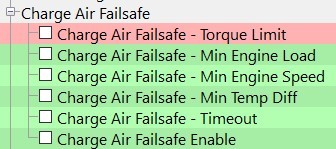
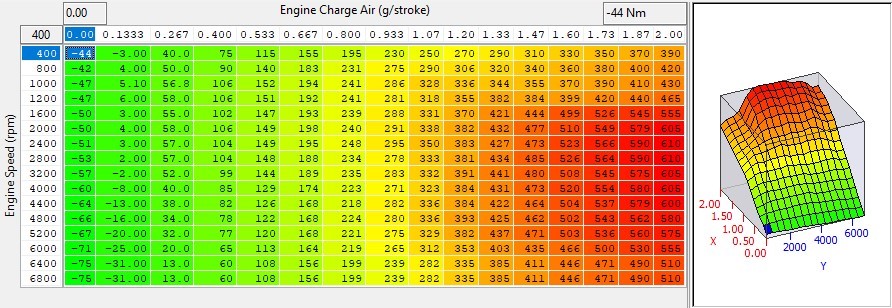
Charge Air Failsafe
The OEM intercoolers on a VR30DDTT engine are water to air, and prone to airlocks in their coolant system after removal and installation. These air bubbles can create high charge air temperatures, the OEM code offers no protection which means an engine can be quickly destroyed at higher boost levels. Adding an element of safety to tuning, a charge air to intake air temperature differential threshold has been created to limit the desired torque to reduce power until the dangerous running conditions subside.
Operation
When enabled the code then checks if the enable thresholds have been met as per the workflow below
- Dig: Charge Air Failsafe Limiter – An on/off parameter to show if the car is in charge air related failsafe modes.
- Charge Air Temp – The intake charge air temperature (post intercooler) in °C.
- Charge Air Coolant Temperature – The W2A intercooler water temperature in °C.
- Intake Air Temp – The intake charge air temperature (pre intercooler) in °C.
Map LIst
Live Data Parameters
- Dig: Charge Air Failsafe Limiter – An on/off parameter to show if the car is in charge air related failsafe modes.
- Charge Air Temp – The intake charge air temperature (post intercooler) in °C.
- Charge Air Coolant Temperature – The W2A intercooler water temperature in °C.
- Intake Air Temp – The intake charge air temperature (pre intercooler) in °C.
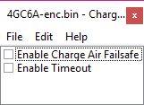
Charge Air Failsafe - Enable
Check these boxes in order to enable the charge air failsafe features.
Charge Air Failsafe - Torque Limit
This sets the maximum allowable torque when the failsafe mode is active. Normal throttle response is allowed until the torque limit is reached.

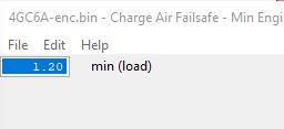
Charge Air Failsafe - Min Engine Load
Sets a minimum engine load the engine must achieve before the Charge Air Failsafe-Torque Limit is applied.
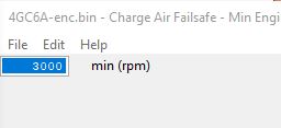
Charge Air Failsafe Min Engine Speed
Sets a minimum engine speed the engine must achieve before the Charge Air Failsafe Torque Limit is applied.
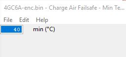
Charge Air Failsafe - Min Temp Diff
Sets a minimum temperature difference that must be reached before the Charge Air Failsafe - Torque Limit is applied
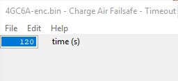
Charge Air Failsafe - Timeout
If the timeout is enabled, the Charge Air Failsafe - Torque Limit will be turned off automatically after the amount of time has passed. If the timeout is disabled the ignition will need to be key cycled in order to release the failsafe mode.
Ignition
For additional information on the topic, check out the VR30DDTT Ignition System Supplement
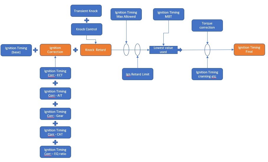
The VR30DDTT platform uses a maximum Best Torque (MBT) timing ma, a base map (knock limited) and an ignition timing maximum allowed map to determine the base timing. It will choose the lowest value of the Base MBT or Max map and then apply the engine condition corrections and the knock detection correction amounts.
There is a safe mode (low octane) map that can be switched to if the car enters limp mode (From DTC's) or high knock levels have been sustained for a set period. The safe mode can sometimes be enabled if the vehicle is refueled but that is yet to be confirmed. The diagram below illustrates the basic control functions and major inputs however there are additional maps and parameters that go in to the system.
Limiters
The VR30DDTT has many safety limiters. Raising the limiters without complete understanding may cause issues or damage to the vehicle's engine. When attempting to generate more power, some limiters may need to be increased or decreased.
Map List
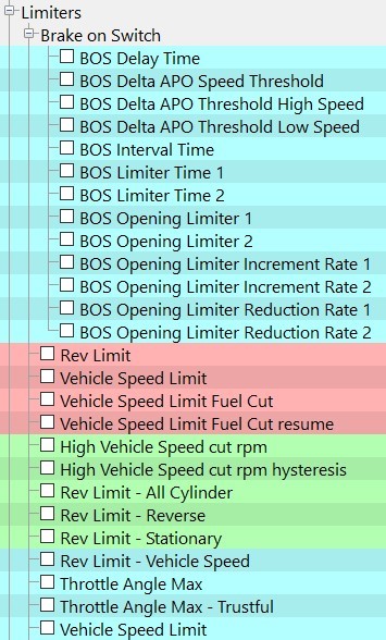
Rev Limit
This is the normal rev limit of the car. It will start with throttle closing and then a partial fuel cut, raise this if required.
Be aware that the TCM has it's own shift limit, so it will always shift at a set RPM

Rev Limit - All Cylinder
This is the full fuel cut "All Cylinder" RPM limit. This value should always be greater than the Rev Limit value.

Rev Limit - Reverse
Rev Limit when in reverse gear.

Rev Limit - Stationary
Rev limit when stationary

Rev Limit - Vehicle Speed
Secondary rev limit at individual vehicle speeds. The TCM will still limit RPM by shifting.
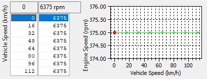
Vehicle Speed Limit
Primary Speed Limiter in Km/H.

Vehicle Speed Limit Fuel Cut & Resume
Fuel cut will enable above the speed set in this table. Fuel will come back on when it falls below the resume value.
Cut: 
Resume: 
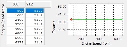
Throttle Angle Max & Trustful
Maximum allowed throttle angle by engine speed. The Trustful map must match this Exactly.
Brake On Switch (BOS) Limiters
As with most modern vehicles there is now a fail safe in order to cut out accelerator pedal input when the brake pedal is being applied at the same time. This is a safety feature to slow the car if the driver or driving signals are not being received correctly in order to prevent the car from accelerating without driver input. This feature can be adjusted or disabled to allow the brake to be applied when applying the accelerator pedal for use while brake boosting etc.
The diagram to the right shows which maps are responsible for which part of the BOS limit process.
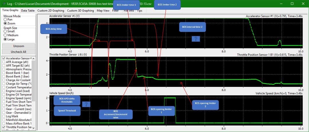
BOS Delay Time
The delay time before the BOS limiter adjusts accelerator pedal output.

BOS Delta APO Speed Threshold
The vehicle speed to differentiate between BOS Delta APO Speed Threshold High Speed & BOS Delta APO Speed Threshold Low Speed.

BOS Delta APO Speed Threshold High Speed
The function of this table as well as it's low speed counterpart are not completely understood, but they appear to be the activation thresholds based on accelerator pedal position. Changing these had little effect on our test vehicle.

BOS Delta APO Speed Threshold Low Speed
The function of this table as well as it's highspeed counterpart are not completely understood, but they appear to be the activation thresholds based on accelerator pedal position. Changing these had little effect on our test vehicle.

BOS Interval Time
The function of this value is currently unknown but may be related to the maximum time allowd before any BOS limits are applied or possibly the time before reactivation.

BOS LImiter Time 1
The time to wait before the BOS Opening Limit 1 accel pedal adjustment is applied.

BOS Limiter TIme 2
The time to wait before the BOS Opening Limit2 accel pedal adjustment is applied.

BOS Opening LImter 1
Limit applied to the accel pedal input for torque calculations while the vehicle is before the BOS Limiter TIme 1, This will need to be raised to allow for more accel pedal to be applied with the brake switch on.

BOS Opening LImter 2
Limit applied to the accel pedal input for torque calculations while the vehicle is before the BOS Limiter TIme 2, This will need to be raised to allow for more accel pedal to be applied with the brake switch on.

BOS Opening Limiter Increment Rate 1
Rate at which the accel pedal is raised from the BOS opening limiter 1 set point when the brake is released. This is likely to be used for the BOS limits applied above BOS Delta APO Speed Threshold. BOS Opening Limiter Increment 2.

BOS Opening Limiter Increment Rate 2
Rate at which the accel pedal is raised from the BOS Opening Limiter 2 set point when the brake pedal is released. This is likely to be used for the BOS limits applied below BOS Delta APO Speed threshold.

BOS Opening Limiter Reduction Rate 1
Rate at which the accel pedal is lowered to the BOS Opening Limiter 1 set point when the brake pedal is applied. This is likely to be used for the BOS limits applied above BOS Delta APO Speed Threshold.

BOS Opening Limiter Reduction Rate 2
Rate at which the accel pedal is lowered to the BOS Opening Limiter 2 set point when the brake pedal is applied. This is likely to be used for the BOS limits applied above BOS Delta APO Speed Threshold.

Sensor Scaling
Sensor scaling is the category that contains all the sensor based scaling factors relevant to tuning the VR30DDTT engine. If there are sensors you wish to replace with aftermarket types use the sensor scaling maps and enter the new values of the sensors (acquired from their manufacturer).
Map List
Live Data Parameters
- AF Sensor B1 (V) – Voltage output of the AFR sensor bank 1.
- AF Sensor B21 (V) – Voltage output of the AFR sensor bank 2.
- AFR Bank 1 (AFR) – Bank 1 Sensor output in AFR counts as seen by the ECU after corrections.
- AFR Bank 2 (AFR) – Bank 2 Sensor output in AFR counts as seen by the ECU after corrections.
- AFR Calibrated – AFR value according to polynomial calculation based on wideband measured AFR.
- Fuel Pressure (MPA) – Absolute measured fuel pressure output of High pressure fuel rail in Mpa.
- Fuel Pressure Sensor (mV) – Voltage output of High pressure fuel rail sensor in millivolts.
- Knock Index - Cylinder 1 to 6 – Knock count value as seen by the ECU for each individual cylinder.
- Knock Threshold – Cylinder 1 to 6 – The set knock threshold output of the knock threshold map.
- Boost Sensor 1 & 2 (bar) – Boost sensor output value in Bar.
- Manifold Pressure Sensor (V) – Voltage output of the Manifold pressure sensor.
- Manifold Absolute Pressure (bar) – Absolute pressure measure in the manifold.
- Mass Airflow (g/s) – Converted Mass airflow after MAF sensor output processing.
- Mass airflow Bank 1 (% load) – Bank 1 specific load converted output of MAF sensor (not corrected).
- Mass airflow Bank 2 (% load) – Bank 2 specific load converted output of MAF sensor (not corrected).
- Mass Airflow Sensor Freq B1 – Bank 1 MAF sensor output frequency.
- Mass Airflow Sensor Freq B1 – Bank 2 MAF sensor output frequency.
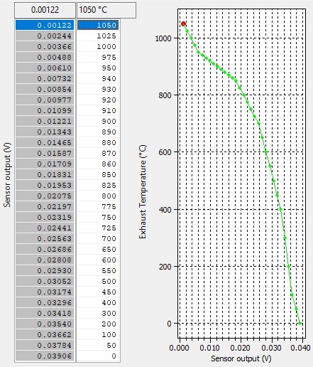
- Exhaust Temp 1 B1 (V) – Voltage output of EGT sensor for bank 1.
- Exhaust Temp 1 B2 (V) – Voltage output of EGT sensor for bank 2.
- Exhaust Temp B1 (°C) – Converted Exhaust gas temperature for Bank 1.
- Exhaust Temp B2 (°C) – Converted Exhaust gas temperature for Bank 2.
O2 Sensor to AFR
This is the map which converts Oxygen sensor voltage into AFR before any corrections are applied.
AF Sensor Correction - Exhaust Pressure Estimate
This map is the exhaust back pressure estimate used in the sensor correction function. If you have repositioned the O2 sensor post turbo or the sensor readings become inaccurate at high loads and speeds, this table may need to be adjusted. If you can measure ehaust pressure and put the measured values into this map it should give you close to an accurate pressure correction.
AF Sensor Correction for Exhaust Back Pressure
This is the amount of AFR correction applied for the estimated back pressure (The left axis is believed to be estimated exhaust pressure not atmospheric pressure. This is used to compensate for inaccuracies causd by measuring the exhaust gas aboove ambient pressure. It should not need to be adjusted unless the sensor has been changed or you need to make corrections because the sensor has moved.
FP Sensor Default
In the event of a wiring or sensor failure the system will default to this fuel pressure.
FP Sensor Max
Maximum output voltage for the sensor. Apply the sensor manufacturers recommended values.

FP Sensor Min
Minimum voltage for the fuel pressure sensor. Apply the sensor manufacturers recommended values.
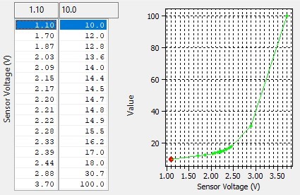
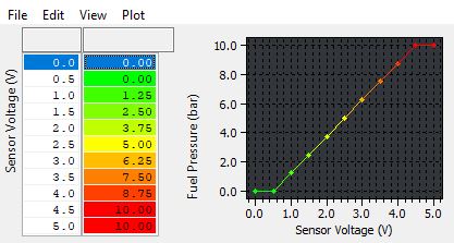
FP Sensor Scaling
The Scaling for the added fuel pressure sensor. Both voltage and pressure (in BAR) are editable. Apply the sensor manufacturers recommended values.
FP Sensor Smoothing
Smoothing value applied to the fuel pressure sensor output.

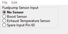
FP Sensor Source
Designates the sensor input hijacked for the addition of a fuel pressure sensor. You can use one of the tip sensors, EGT or the spare ECU pin 60.
Fuel Pressure Scaling - Pressure Offset
The offset for pressure scaling in MPa, scale this in the same method as MAP sensor scaling.

Fuel Pressure Scaling - Voltage Multiplier
The value in MP/a volt used to convert sensor voltage to pressure. Scaled similarly to a MAP sensor.

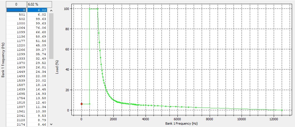
Knock Frequency Masking
The Nissan/Infiniti strategy for knock sensor signal analysis takes windowed knock signals and sums up the amplitudes based on separate frequency bands. If you have a forged engine that makes more noise due to the differences in clearances etc. You may want to use these masks to try to reduce or eliminate "False Knock"
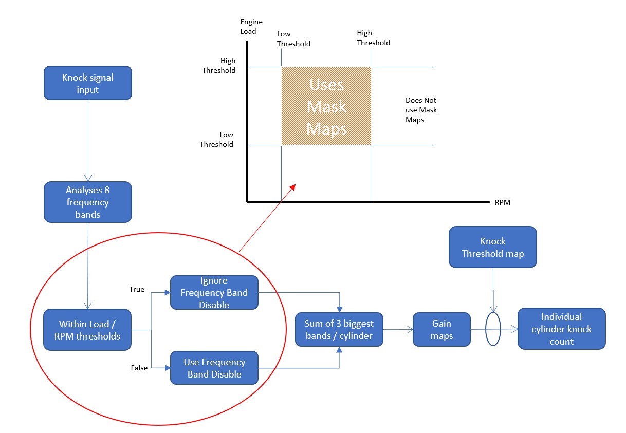
Frequency Mask - Enable (Disable) Switches
We believe that the frequencies that are disabled go from top to bottom.
- 6.1kHz
- 7.3kHz
- 8.5kHz
- 9.8kHz
- 11.0kHz
- 12.2kHz
- 13.4kHz
- 14.6kHz
Frequency Mask - Cylinder Charge Lower Limit
The load threshold the engine load must be above in order for the masking maps to be used.
Frequency Mask - Cylinder Charge Upper Limit
The load threshold that the engine must be below in order for the masking maps to be used.
Frequency Mask Cylinder Charge Hysteresis
Hysteresis value for the engine load thresholds.
![]()
Frequency Mask Engine Speed Lower Limit
Engine speed threshold for enabling the knock masking maps.
Frequency Mask - Engine Speed Hysteresis
Hysteresis value for engine speed thresholds.

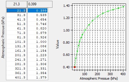
Map Sensor Scaling - Pressure Offset
This is the sensor located in the inlet manifold used for airflow estimation and pressure control. The standard sensor is 3.0bar absolute sensor. There is shared scaling for the MAP and pre-throttle boost sensors so all three sensors must be adjusted in order to keep the measurements correct. This is the pressure offset value to adjust the conversion output of the sensor to the calibrated 0 point.

Map Sensor Scaling - Voltage Multiplier
This is the sensor located in the inlet manifold used for airflow estimation and pressure control. The standard sensor is 3.0bar absolute sensor. There is shared scaling for the MAP and pre-throttle boost sensors so all three sensors must be adjusted in order to keep the measurements correct. This is the voltage multiplier to set the slope of the boost sensor output.

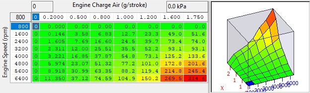
MAF sensor Q-HZ Conversion Bank 1 & 2
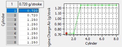
Mass airflow sensor frequency to air flow conversion table. The mass air flow sensor is placed in the intake air stream measuring a part of the entire intake flow and outputting a frequency back to the ECU. It measures the frequency from both MAFs and uses the load output of each one to calculate a respective airflow. To tune the fuel trims you should adjust the load output of these maps for given frequencies.
BFS Multiplier (K-Factor)
This is a conversion factor that is used to generate engine load and fuel volumes. It should not need to be adjusted.

MAF Sensor Scale (% to g/sec) for Load
When fitting larger MAF housings (or induction kits) then this value should be increased proportionally relative to the surface area increase of the larger MAF housing. This is a coarse adjustment for MAF scaling. It converts the MAF sensor % value into grams of air per second.
The factory default value is 138 for the factory 62mm MAF tube, this should be increased to 209 for 76mm MAF tubes. This is based on the surface area increment amount. The surface area calculation is as follows: Radius squared * PI = Surface area
Example Calculations
62mm MAF tubes:
31mm Radius, 31x31=961mm2, 961 * 3.14 (Pi) = 3017mm2
76mm MAF tubes:
38mm Radius, 38x38=1444mm2, 1444 * 3.14 (Pi) = 4534mm2
Now if we divide the new 76mm MAF housing surface area by the stock 66mm MAF housing surface area we get the percentage increment amount.
4534/3017 = 1.502 or if you prefer ‘the 76mm MAF tubes have a 50% greater surface area’.
So if we simply multiply the 1d map called ‘MAF Sensor Scaling (% to g/s) for Load’ by 50%
153 * 1.50 = 209.
If the MAF tubes are 69.5mm (2.75 inch) then enter 174

Enter a value of 206 for 76mm MAF tube or 174 for 69.5mm MAF tube
Exhaust Temperature Scaling
Sensor voltage output conversion to temperature. This will need to be changed if the sensors are changed or removed. There is common scaling for both banks.
Torque
The VR30DDTT uses torque targets in order to control requested throttle airflows and power demand. Torque reduction requests are also released through these strategies. Similar to other Nissan platforms there are powertrain torque demand maps, torque output maps, limits and torque corrections.
Map List
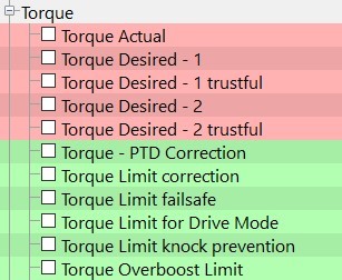
Live Data Parameters
- Torque Actual (Nm) – Estimates Actual Engine Torque Produced.
- Torque Demand 1 (Nm) – Demanded torque for powertrain
- Torque Demand 3 (Nm) – Demanded torque for other units
- Torque Limit (Nm) – Current safety limit for torque
- Torque Red Req – Time Since Gear (s) – Gear sift timer from torque reduction request release
- Torque Red Req 1 (Nm) – Torque reduction request from transmission
- Torque Red Req 2 (Nm) – Torque reduction request from other modules
Torque Actual
Estimates actual engine torque and is used by the TCM and other modules to decide on the amount and level of torque reduction.
Torque Desired - 1&2 (as well as Trustful)
The trustful equivalent map must match exactly or P0605 DTC's will occur
The demanded torque from the power train. There are two modes and the #1 maps appear to be used most of the time. The silver sport cars have a lower target from the factory. As such these tables must need to be raised to get boost to increase.
Torque - PTD Correction
The Powertrain Torque Desired correction based on current gear ratio. Adjusts torque demanded in different gears.
Torque Limit Correction
This is an adjustment to the torque limit based on temperature.
Torque Limit Failsafe
This is the maximum allowed torque in failsafe mode.
Torque Limit Drive Mode
The maximum torque allowed when in drive. Currently set to maximum.
Torque Limit Knock Prevention
This is the maximum allowed torque value for coolant temperature in order to prevent knock.
Torque Overboost Limit
This is the maximum allowed torque when overboost is detected.
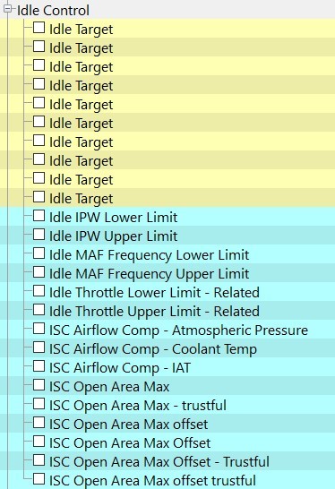
Idle Control
Idle control is done using the electronic throttle, the function uses a similar method to other Nissan products.
Map List
Live Data Related Parameters
- Engine Speed (RPM) – Current engine speed
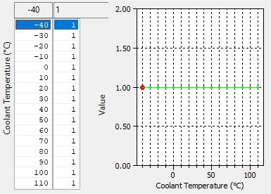
- Coolant Temperature (°C) – Current engine coolant temperature
- Mass Airflow Sensor Freq B1 – Bank 1 MAF sensor output frequency
- Mass Airflow Sensor Freq B1 – Bank 2 MAF sensor output frequency
- Intake Air Temperature (°C) – Current intake air temperature
- Atmospheric Pressure (Bar) – Current Barometric Pressure
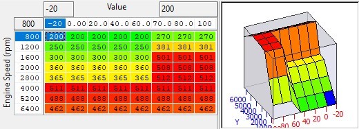
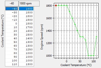
Idle Target
There are many idle target maps identified. Currently we are not aware of how the ecu selects which one to be used. As they all retain coolant temperature as the axis, it's likely one is used as a primary table and the others are used in modes such as immediately after start, limp modes, and as target limits.
Idle IPW Upper / Lower Limit
Upper and Lower limit of injector pulse width to allow idle flag to be set.

Idle MAF Frequency Upper / Lower Limit
These maps set the idle MAF frequency bounds for the idle flag. There are also thresholds based on RPM and time.

ISC Airflow Comp - Atmospheric Pressure
This is a compensation to Idle Speed Control (ISC) airflow target based on the atmospheric pressure. It should not need to be adjusted unless idle airflow requirements have changed significantly with different throttles or intake systems.
ISC Airflow Comp Coolant Temp
This is a compensation to idle airflow target based on the engine coolant temperature. It should not need to be adjusted unless idle airflow requirements have changed significantly with different throttles or intake systems.
ISC Airflow Comp - IAT
This is a compensation to idle airflow target based on the Intake Air Temperature. It should not need to be adjusted unless idle airflow requirements have changed significantly with different throttles or intake systems.
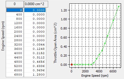
ISC Open Area Max & Trustful
This is the base value for Maximum idle open area referencing coolant temperature the other offsets are added to the output of this map. The final value is used to cap the allow idle open area. 2D RPM based Offset limiter & Trustful .
This will limit the open area adjustment based on engine speed, it will cap the adjustment to maximum allowed open area. The trustful map of the same name must match this map exactly otherwise DTC’s will occur. The intent of this map is to allow the base idle throttle open area to be increased with RPM.
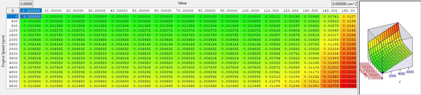
3D Torque Based Offset Limiter & Trustful
This will limit the open area adjustment based on available torque and engine speed. It will cap the adjustment to allowed open area. The trustful map of the same name must match this map exactly otherwise DTC's will occur. It is believed currently that these maps are only used in hybrid vehicles not the current VR30DDTT lineup.
Upper LImit
This is the theoretical injector open time for the misfire diagnosis system to be active when the idle flag is set.
Beta map! Use with caution!

Lower LImit
The maximum allowed engine speed for misfire diagnosis when idle flag is active.
Beta map! Use with caution!

Radiator Fan Control
Radiator fan speed for coolant temperature control is performed by the ECM. The fan speed and activation points can be adjusted in the calibration to cope with increased cooling demand and changed radiator airflow characteristics.
Map List
Live Data Related Parameters
- Radiator Coolant Temp (°C) - Current Radiator Temperature.
- Fan Duty (%) - Current requested duty for the radiator fan
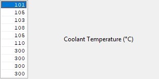
Radiator Fan Threshold
These values for the coolant temperature axis of the radiator fan speed control maps. The values are interleaved so the first 2 values are the first thresholds for each map.
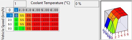
Engine Demand Fan Speed
The engine demand for radiator fan speed. X axis is coolant temp with values of 0, 101, 103, 105, 300, 300.
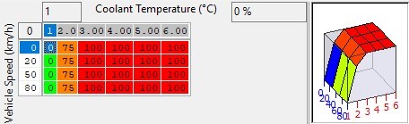
Engine Demand Fan Speed - High Temp
The engine demand for radiator fan speed when the coolant is at high temp. X axis is coolant temp with values of 0, 105, 108, 110, 300, 300.
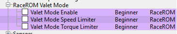
Valet Mode
Valet mode allows the driver to lock the car into a lower performance mode when lending it to a less experienced driver, or as a theft deterrent that kicks in when the car is at a safe distance. Valet mode has been simplified in line with the strategy used on the 370z, as the previous version was frequently commented on as being too complicated to activate and deactivate.
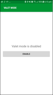
EcuTek ECU Connect Valet Mode
- Link with your vehicle by plugging in the EcuTek Bluetooth Dongle
- Select the "My Car" option
- Enter the "Valet Mode" option
- Press enable to activate valet mode, or disable to turn it off.
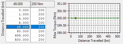
Valet Mode Torque Limiter
When Valet Mode is active the torque output can be limited to prevent a car being driven hard or recklessly. For use as an anti-theft measure it would be reasonable to reduce these values from the default 200Nm after a short distance.
Valet Mode Speed Limiter
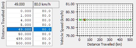
When Valet Mode is active the maximum speed can be limited to prevent the car from being driven at anything beyond a sedate pace. For use as an anti-theft measure it would be normal to significantly reduce these default values to as low as zero after a shorter distance.
Glossary of Terms
- AFM - Air Flow Meter.
- AFR - Air Fuel Ratio.
- Calculated Air Flow - The ai flow sensor voltage is not linearly related to the amount of air flow. The ECU uses a scaling map to translate the air flow sensor voltage into an air flow rate value called calculated air flow.
- ECM - Engine Control Module.
- Engine Load - The ECU calculates engine load based on calculated air flow divided by engine RPM. It is effectively how much air enters the engine on each revolution.
- FTST - Fuel Trim Short Term.
- FTLT - Fuel Trim Long Term.
- FMIC - Front Mounted Intercooler.
- MAF - Mass Air Flow (sensor).
- MAP - Manifold Absolute Pressure (Sensor) a measure of pressure where the zero point is a vacuum.
- MRP - Manifold Relative Pressure or boost pressure. A measure of pressure where the zero point is barometric pressure either at sea level or local.
- MBT - Maximum best torque or minimum best timing.
- O2 Sensor - Lambda or Oxygen Sensor. Analyzes the parts of unburnt fuel vs. oxygen content found in the exhaust stream of the engine.
- RRLC - RaceRom Launch Control.
- RRBC - RaceRom Boost Control.
- RRFF - RaceRom Feature File.
- SD - Speed Density, the amount of air movement (mass airflow) in grams is calculated via the MAP sensor rather than the MAF sensor.
- TCM - Transmission Control Module or Gearbox ECU.