Mazda MX5 Tuning Guide
- Brandyn Mowat
ProECU Tuning Guide
Live Data Display
ProECUMazda MX-5 can offer real time exceptionally high speed data display and the ability to log this displayed data (note: there is no real time editing as the maps are stored in Read Only Memory). To start live map access, connect to the car and click on the ‘Map Access’ button.Ensure that the ROM you are viewing is the same one as that within the ECU.Note: It is also possible to change the columns by right-clicking on a column and then selecting or deselecting a column name. We have enabled the Minimum and Maximum, as shown.
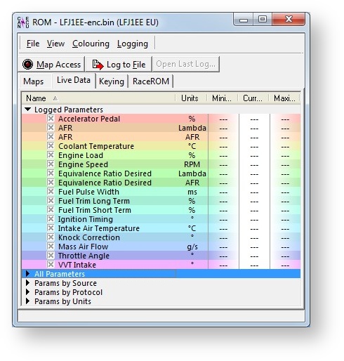
Table of Contents
Supplemental Content
Platform Specific
General
Accelerator
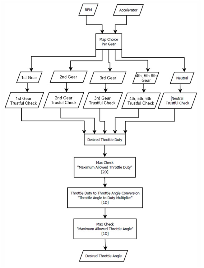
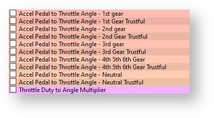
These maps set the base throttle duty requested by the accelerator pedal and RPM, allowing detailed profiling of the throttle maps to suit the driving requirements. The limiters will only need to be adjusted if your profile exceeds their set limits. The “Maximum Allowed Throttle Opening” map is usually set to the maximum angle of the throttle butterfly, and should not need to be adjusted. There are five trustful maps which must be profiled to exactly the same as their corresponding per gear map otherwise you will get a checksum DTC error. The throttle duty to angle multiplier converts the throttle duty value to an angle for use in the feedback and diagnostics systems this should not be changed unless you have changed the throttle body.
Map List
Live Data Parameters
- Accelerator Pedal - Position of the accelerator pedal from 0 – 100%
- Accelerator Pedal Position #1
- Accelerator Pedal Position #2
- Accelerator Pedal Position Sensor #1
- Accelerator Pedal Position Sensor #2
- Throttle Angle - Angle of the Throttle measured from 0-100%
- Throttle Angle Desired
- Throttle Position #1
- Throttle Position #2
- Throttle Position Actual
- Throttle Position Desired
- Throttle Position Sensor #1
- Throttle Position Sensor #2
Camshaft Timing
This map controls the angle of the intake cam (note that 1 degree at the camshaft is 2 degrees at the crankshaft). This number is in camshaft degrees before Top Dead Centre. Modifying the cam timing map can increase power and torque, but too much advance can significantly change cylinder pressures. This map should be tuned if any item is added to the engine that may change the VE.
Map List
Live Data Parameters
- VVT Intake - This shows the inlet vairiable valve timing angle in degrees.
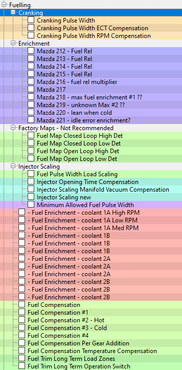
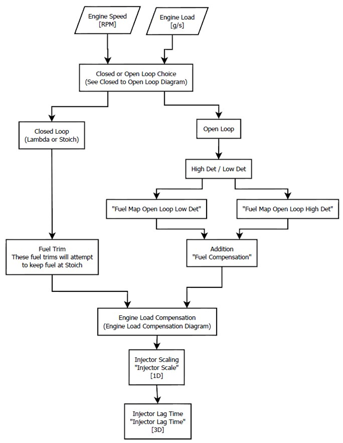
Fuelling
There are four 3D maps which control the base fuel calculation. “Fuel Map Closed Loop High / Low Det” and “Fuel Map Open Loop High / Low Det”. This sets the base AFR to which the car then adds the fuel adjustments. During Closed Loop operation (controlled by Open Closed Loop Thresholds which will be explained in further detail) the ECU will attempt to maintain 14.7:1 AFR or Lambda 1. This only changes when the vehicle switches into Open Loop, at which time it will disregard the feedback control and attempt to meet the Open Loop fuel map target. The 3D “Fuel Compensation” map is subtracted from the base map to provide a manual adjustment. This can be set to 0 under normal operation and the Open Loop Fuel Map used to control the required AFR.
Map List
Live Data Parameters
- AFR Monitors - Shows the actual AFR calculated from the AFR Sensor (V) from the factory AF Sensors before the Catalytic convertor. AFR readings should always be calibrated with your own trusted wideband sensor as normal. In our experience the factory wideband sensor reads a leaner AFR on full load than the actual AFR. There are separate data parameter for displaying Lambda or AFR.
- AFR (AFR)
- AFR (Lambda)
- AFR Actual
- Equivalence Ratio - The desired closed loop AFR the ECU is trying to meet. This only referenced in closed loop mode. Fuel Pulse Width (ms) The opening period for each injector.
- Equivalence Ratio Desired (AFR)
- Equivalence Ratio Desired (Lambda)
- Fuel Trims - This is the percentage of fuel trim that the ECU adds or subtracts from the injector open time to reach the Target AFR shown in the Fuel Map.
- Fuel Trim Short Term (%)
- Fuel Trim Long Term (%)
- Injector Pulse Width (ms)
- The amount of time the fuel injector is active in MS
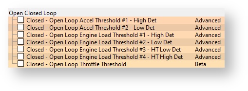
Open / Closed Loop
These thresholds set the points at which the ECU changes from closed loop to open loop operation. When any of these conditions are exceeded, the engine will switch; this switch is most obviously shown on the fuel map, as it will change from 14.7:1 to whatever is set in the “Fuel Map Open Loop High / Low Det” map.
How to Calibrate Larger Injectors
It’s very important that the ECU knows the true size of the fuel Injectors that are fitted so it can accurately calculate the correct time period to open the injectors to deliver a required volume of fuel.
After fitting larger port injectors the following maps will need rescaling.
- Injector Scaling (Generally the replacement larger Port Injectors will be supplied with an Injector calibration size and that should be entered.)
- Injector Opening Time Compensation
- Injector Scaling Manifold Vacuum Compensation
The standard injector size is 280cc, and is calibrated at 380kPa. The “Injector Scale” map is used to set the size for the injector to ensure correct calculation of fuel. The “Injector Open Time Compensation” sets the voltage and pressure compensation for the injectors and can be calculated using the data published by the manufacturer of injectors. This should not be changed unless the injectors are changed to a different size, type or manufacturer. Please refer to the tuning section for further information on how to calibrate the Injector Lag Time. Vehicles running very large injectors will need to have the Minimum Allowed Fuel Pulse Width Value lowered to allow the injectors to open for a very small period of time, this is either a 2D map against ECT or a 1D value.
Injector Scaling
Generally the replacement larger Port Injectors will be supplied with an Injector calibration size and that should be entered.
Injector Opening Time Compensation (Lag Time)
The different Injectors will have different characteristics to the stock injectors and will normally take longer to open. This time period is referred to as ‘dead time, lag time or latency’ and this time period is affected by the current battery voltage. Using the manufacturers technical data, enter the correct lag times for a given voltage in the maps called ‘Injector Opening Time Compensation’. If this data is not available then we suggest you just change the Injector size then leave the battery voltage comp map until you see how the engine is currently running.
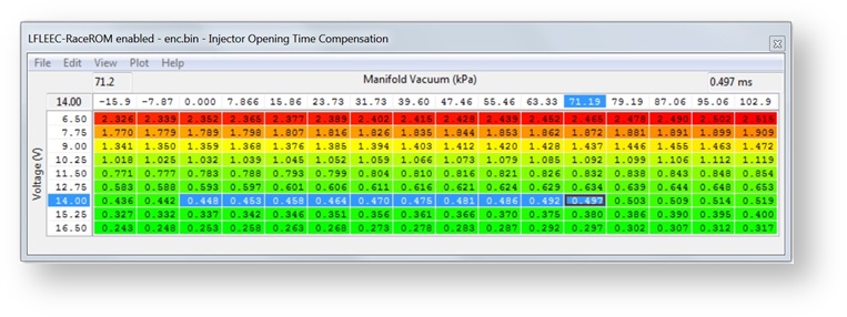
The X axis is for Battery Voltage and is common to most Injector Open Time Compensation calculations.
The Y axis is Manifold Vacuum and is more complex and difficult to visualise at first glance but if you consider the MX5 has a Naturally Aspirated engine and was not calibrated for positive pressure (Forced Induction) then this helps the understanding.
At sea level with the engine off, the X axis will be in the zero column. With the engine running at Idle it will be around 63 to 79 kPa column depending on your current inlet manifold depression.
For a turbo or supercharger vehicle then any positive boost pressure will move to the far left of the map and -15.9 kPa is actually 15.9 kPa of boost pressure, the X axis should be rescaled for high boost levels.
So,
- -102 kPa would be 1 bar boost
- 0 kPa is 1 bar absolute
- 102kPa is just under 0 bar absolute
A custom logging parameter Manifold Relative Pressure has been added to the RaceROM Custom Live data list to aid in identifying which cell you’re using.
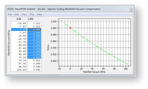
Injector Scaling Manifold Vacuum Compensation
This 2D map has again an input axis as Manifold Vacuum and the following conversions should be noted to make the map easier to visualise and understand.
- -102 kPa would be 1 bar boost
- 0 kPa is 1 bar absolute - sea level
- 102kPa is just under 0 bar absolute and full vacuum
When fitting larger injectors the following sequence should be followed.
- Set the Injector Scaling Size.
- Set the 3D Battery Voltage Compensation (Lag Time) map as per the manufacturer’s specification for the Injectors that you are fitting.
- Set the 2D Injector Scaling Manifold Pressure Compensation map, this should be used for the majority of Injector calibration. This map has a major effect on Injector open time (ms) and should be used to dial in your FT in closed loop and hit your Fuel map AFR targets in open loop.
Setting the 2D Injector Scaling Manifold Vacuum Compensation map should be done in a similar way the MAF rescaling section.
Fill the higher load section of the fuel map with a fixed value like 12:1 AFR and then adjust the 2D Manifold Pressure Comp map to achieve the 12:1 AFR fuel map target when in Open Loop.
Now repeat the sequence for Closed Loop (14.7:1 AFR), so adjust the 2D map until the Fuel Trims are within +/- 10%.
Note: the Injector Opening Time Compensation values will have much more of an effect at Idle and light load when the Injector open times are much smaller (2-5ms at Idle and light load VS 1018ms for full load) in addition the Injector Scaling Manifold Pressure Comp values will have the greatest affect overall.
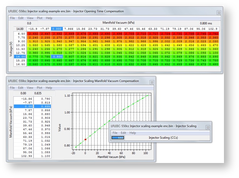
You can see below all 3 maps have been adjusted to calibrate these 550cc Injectors correctly. When the vehicle is forced induction then we need to rescale the critical 2D Injector Scaling Manifold Pressure Compensation map.
If you have very large injectors fitted you may also need to adjust the Minimum Allowed Fuel Pulse Width 1D value to allow the injectors to open for a very small period of time.
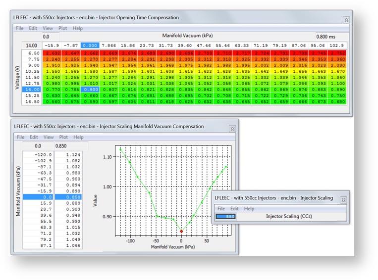
DW550cc Injector setting for NA and FI setups
You can see below the 2D map has been rescaled on the Input axis for the positive boost pressure (FI setup). The map has now changed to a V shape with the lowest compensation values around 1bar absolute (0 psi boost). The exact reason for this shape is currently unknown but the combination of correct Injector scaling size, Injector Opening Time Compensation (Lag Time) set as per the manufacturer calibration and an accurately scaled Manifold Pressure compensation map produced an accurately scaled Injector scaling where FT were within +/-10% and the AFR achieved matches the fuel map.
Idle
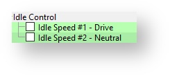
These are two distinct modes for the idle speed; when the car is in gear, clutch up, with no accel pedal, controlled by “Idle Speed #1 – Drive”, and out of gear, no accelerator pedal, controlled by “Idle Speed #2 – Neutral”.
In addition to those tables there are two idle ignition control maps which set the ignition timing at idle based on desired RPM and engine load.
Map List
Intake Manifold Runner Control
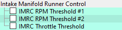
The Intake Manifold Runner Control adjusts the variable length runners in the inlet, altering the speed and quantity of air flowing into the cylinder, in turn adjusting the torque and power characteristics of the engine. At idle and low loads the intake manifold runners are “on” or in the long position. If the throttle exceeds the threshold in the “IMRC Throttle Threshold” map, they switch to “off” or shorter runners. If the RPM Exceeds “IMRC RPM Threshold #1” The runners will switch “on”, and when it exceeds “IMRC RPM Threshold #2” it will switch “off”. The RPM thresholds take precedence over the throttle threshold, so be mindful when setting the thresholds.
Map List
Live Data Parameters
- IMRC Control - Status of the intake manifold runners.
Ignition
Ignition Base Maps
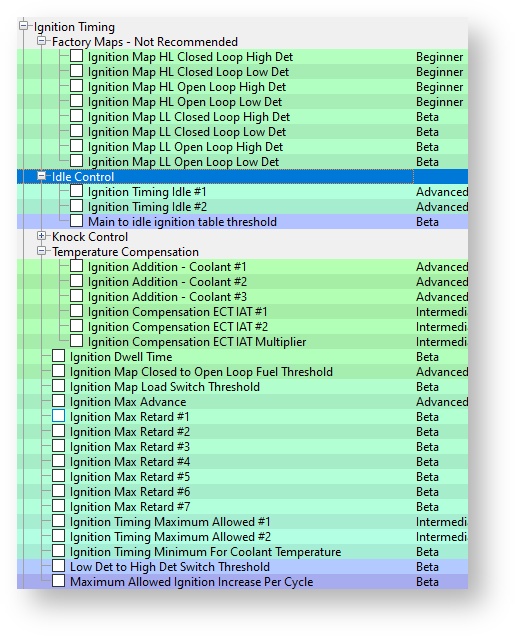
There are four ignition base maps that set the ignition timing. These are chosen by Closed Loop High / Low Det, or Open Loop High / Low Det. The threshold for the Closed to Open Loop switch is set by the 1D value “Ignition Closed to Open Loop Fuel Threshold”. This sets the AFR at which the ECU changes map. The threshold between High and Low Det maps are controlled by the 2D map “Low Det to High Det Threshold” and will be explained in the Knock Control section. The ignition temperature compensations are applied to the value of the base ignition timing.
Ignition Timing Compensation
There are two sets of temperature compensation for ignition timing. “Ignition Compensation ECT IAT #1 or #2” are multiplied by “Ignition Compensation ECT IAT Multiplier”, and then subtracted from the base ignition timing. The three 3D maps, “Ignition Addition – Coolant #1 - #3” are added to the ignition timing.
Map List
Live Data Parameters
- Ignition Timing (Deg) - The actual Ignition timing angle the ECU used after Knock Correction was applied.
Knock Control
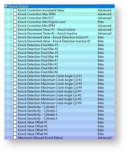
These maps control how knock retard is added and removed from the ignition timing on the detection of detonation. They can be found under the “Ignition Timing” category. The “Knock Correction Max / Min RPM / Min ECT” control when the ECU turns the knock correction on and off. It is disabled by default below 1000 RPM and above 5500 RPM to avoid phantom knock as the engine vibrates.
There is a sensor scaling map “Knock Sensor Scaling” which can be used to adjust the overall sensitivity of the knock sensor. This is covered in more detail in the “Sensor Scaling” category.
Map List
Live Data Parameters
- Knock correction - The amount of ignition retard in degrees removed due to engine knock.
Limiters
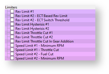
The rev limiters act by disabling the injectors when the RPM exceeds the threshold, and will reenable when the RPM drops below the hysteresis margin. There are two different engine speed limiters, one acts by cutting the fuel and the other reduces the throttle angle, both need to be raised if you want to raise the engine speed. Two different rev limits can be set based on engine coolant temperature, so a lower limit can be enabled when the vehicle is cold. There are two separate speed limiters throttle cut and fuel cut. They each have separate minimum RPM and hysteresis values.
Map List
Live Data Parameters
- Engine Speed - Number of revolutions per minute of the engine
- Vehicle Speed - Vehicle Speed
Load
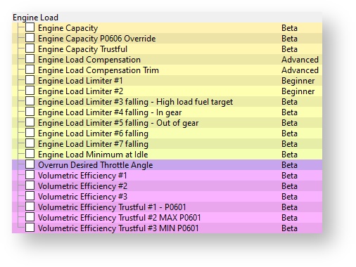
The engine load compensation maps are used to calibrate the conversion from MAF to actual cylinder fill in g/rev. For most tuning these maps do not need to be changed as they have been carefully calibrated by Mazda. If significant modifications have been made or a forced induction kit has been fitted these may need to be altered to make sure the Engine Load is correct. The Engine Load Limit maps control the maximum engine load for the ECU calculations. If the actual engine load exceeds these values then it will be capped. If a forced induction kit is fitted or significant modifications have been made such as camshafts then these values will have to be raised to accommodate the increased airflow
Map List
Live Data Parameters
- Engine Load - Engine load is one of the primary inputs used in the 2D and 3D map lookups. On many older ECUs and aftermarket ECUs this would be manifold pressure. However, the Mazda ECUs meters mass air flow to determine load (V.E.) by calculation against RPM. This method of metering load is very useful, since it is highly resilient to changes to other components in the system, such as exhausts, turbos and intercoolers, as well as changes in air density. However, its weakness shown when induction kits are fitted, if airflow through the sensor element is changed (for example: lead length of tubing before sensor or open filter element), then the MAF calibration is typically no longer accurate. This will cause the ECU to apply inappropriate fuel and timing changes that are based off a (now) incorrect airflow measurement. The uncalibrated sensor can either read high or low or both across the entire voltage range.
- Engine Load Absolute
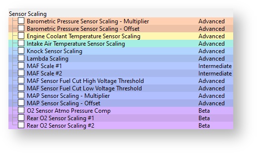
Sensor Scaling
The voltage scaling for several sensors can be changed to suit aftermarket components. E.g. larger capacity MAF sensor, or MAP sensor. The “MAF Scale #1 & #2” should always be set the same, as the ECU is hardcoded to use a particular map, but it is impossible to state which map is used so. The knock sensor scaling can be used to dampen / enhance the knock sensor if phantom knock is detected. Care should be taken when adjusting this map as it may cause damage to your engine if knock occurs and no knock correction is performed. Conversely, an overly sensitive map will cause knock correction to be removed from the ignition unnecessarily.
How to setup an Intake or Induction Kit
It’s very important that the ECU knows the true amount of mass airflow (grams per second) that is entering the engine so it can accurately calculate the correct volume of fuel to inject and therefore achieve the correct AFR that’s shown in the fuel map. The factory fuel map has been calibrated to a stock factory intake and the values are what the vehicle runs when the mass airflow entering the engine is accurate. When fitting most aftermarket intakes, induction kits or even replacement panel filters, the MAF sensor reading will be altered and the MAF sensor scaling will need adjusting. Generally the Inside Diameter (ID) of an aftermarket MAF tube will be larger than the stock MAF tube. Most Intakes will change the way the air flows through the MAF tube and thus across the MAF sensor itself, this results in a lower MAF sensor voltage output that is given to the engine ECU for the same mass airflow. This lower mass airflow reading will lead to a lower engine load, more advanced Ignition timing and a leaner AFR. It’s very important that the MAF scaling is adjusted (normally by increasing values) to counteract this problem.
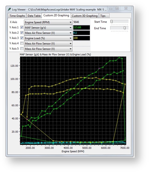
The preferred setup would be making a ‘before and after’ log file showing the MAF volts, mass airflow, engine load, AFR etc for the stock intake and then new intake. You can then cross reference the MAF Volts ‘before and after’ for each RPM and Manifold Pressure and increase the MAF Sensor scaling right hand column (grams) until the same mass airflow reading is achieved with the new intake compared to the old intake. This can be seen on the left where two log files (Before Intake and After Intake) are added together, when the new Intake with larger Internal Diameter (ID) was fitted the MAF Sensor reading dropped from 115grams to 98 grams and the Engine Load dropped from 100% to 85%. This reduced the Injector open time significantly making the AFR very lean and the Ignition Timing over advanced causing severe knocking.
Now this situation where we can fit the Intake and make a ‘back to back’ log like this doesn’t always happen, quite often the vehicle already has an Intake fitted. So in this case the existing Long Term Fuel Trims will be very important and can be used to make the MAF calibration.
Before starting a MAF calibration a simple formula for engine efficiency should be understood to ensure you are adjusting the map correctly.
By multiplying the peak Mass Airflow g/s value by 1.25 (or nearer 1.2 on some engines) you should get the BHP power output of the vehicle, it is also close to the wheel hp of the vehicle, this is a rough calculation but can save a lot of time especially if the vehicle has fundamental issues like air leaks, fuel pump issues or bad MAF sensors etc.
Examples:
- Stock Mazda MX5 pulls around 135 grams of Mass Airflow 135 * 1.25 = 168bhp
- Stock Mazda 3MPS pulls around 210 grams of Mass Airflow 210 * 1.25 = 262bhp
- Stock Mitsubishi EVO X pulls around 250 grams of Mass airflow 250 * 1.25 = 312bhp
- Stock Subaru BRZ pulls around 145 grams of Mass airflow 145 * 1.25 = 182bhp
Engines that have been produced more for torque and fuel consumption over ultimate peak power will have a reduced efficiency ratio factor more like 1.2
- Stock Nissan 370z pulls around 270 grams of Mass airflow 270 * 1.2 = 324bhp
Below you can see we added Power Estimate (BHP) and Injector Duty (%) into the log file
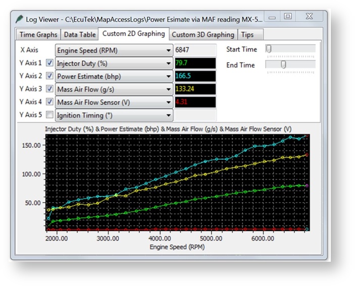
So if you supercharged your MX5 or BRZ/86 and it’s pulling 380g/s at 0.5bar boost but only making 260 - 270bhp (as expected) then something is really wrong (like Injector Scaling, MAF housing design Fuel Pump delivery). If your MAF sensor reading is massively over or under reading then it can be caused by air turbulence in the MAF pipe, if it’s too close to the compressor or re-circ valve or it located near a bend in the MAF intake, it can also be affected if it’s too close to a bolt on air filter.
Adjusting the MAF scaling in closed loop
At Idle and light load (Closed Loop condition) you should log Fuel Trim Short Term (FTST) and
Fuel Trim Long Term (FTLT), generally the MAF reading will be lower with a different intake so the
FT will be adding +% to maintain closed loop 14.7AFR. Any continuous STFT will be transferred to LTFT for improved closed loop control. You should be watching both STFT and LTFT or the EcuTek Combined FT log parameter.
Typically the FT’s will be adding +5% to +20% to maintain the closed loop target. So if we increase the whole MAF scaling by plus 5% this will make a coarse MAF scaling adjustment that will work quite well. Then continue to log and adjust the MAF scaling until the FT are within 10%, a good tuner will aim to have their Fuel Trims within plus or minus 5%.
Adjusting the MAF scaling in open loop
Short Term Fuel Trims do not work in Open Loop so MAF scaling in Open Loop needs a slightly different approach.
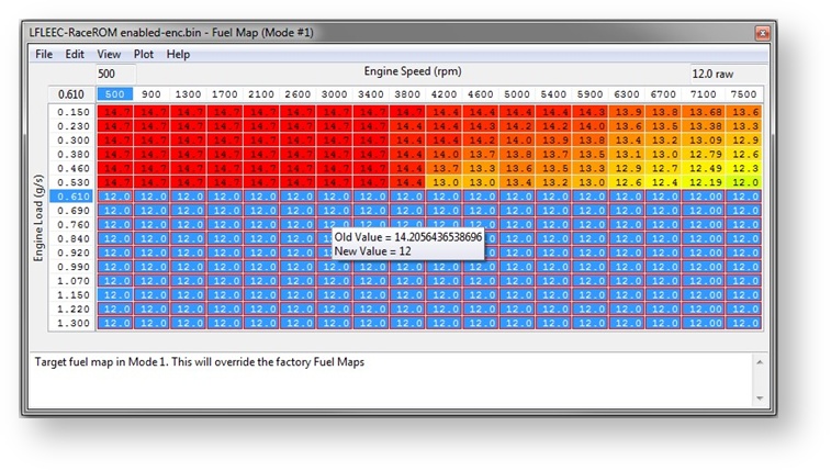
To make a good MAF scaling (and this applies to forced induction conversions as well) we should fill the right hand side of the fuel map with a safe and friendly AFR, we will choose 12:1 AFR as shown below. Now make a power test and once the Engine Load exceeds 0.70 (g/rev) then the AFR should be 12:1.
- If the AFR is 14:1 then increase both 2D MAF scaling (g/sec) at that particular MAF voltage.
- If the AFR is 10:1 then reduce both 2D MAF scaling (g/sec) at that particular MAF voltage.
With a 12:1 AFR Target you should aim to get the AFR within 11.5:1 and 12.5:1 AFR across the board, good tuners will aim for 11.8 to 12.2 AFR but it depends on the time you have available.
The first time you make a MAF scaling in this way it may take a while but once you master the process then in future you will be tweaking the MAF curve on every flash.
Once the MAF scaling is good and smooth and you have 12:1 across the power curve, then you can profile the fuel map to your preferred AFRs.
In Open Loop (high load), the fuel trim feedback does not work anymore (no Short Term Fuel
Trim) but Long Term Fuel Trim’s that had been learned from Closed Loop could be applied in Open loop, this is why it’s very important to get your Closed Loop Fuel Trims tight.
The longer the intake has been fitted the more accurate the FT Long Term will be, this will be a good indication on how far the MAF scale needs to be adjusted by.
Make sure that your Engine Load does not exceed the Y axis of the Fuel and Ignition maps, if it does then rescale the Engine Load axis so you do not reach the maximum engine load value in your log file.
Adjusting the MAF Scaling Using SD
Another option for creating a new MAF curve (MAF scaling) can be to enable SD mode, with SD enabled the mass airflow (g/sec) will come from the SD VE map and not the MAF sensor itself.
But the LIVE DATA custom logging parameter called ‘MAF Sensor’ can still LOG the output of the MAF sensor (even though the MAF sensor is NOT actually used for the load input at all).
Though this can be confusing to start with it is great for MAF scaling on relatively stock cars. Simply enable SD and the engine should run reasonably well then make a power run and be sure to include the logging parameter called MAF Sensor (g/s).
As seen below the ECU is running on SD, the Mass Airflow g/s is coming from the SD map not the MAF sensor and the engine is running well.
We can see and log the MAF Sensor output (the CYAN line) and it’s under reading compared to the more accurate SD Mass Airflow calculation.
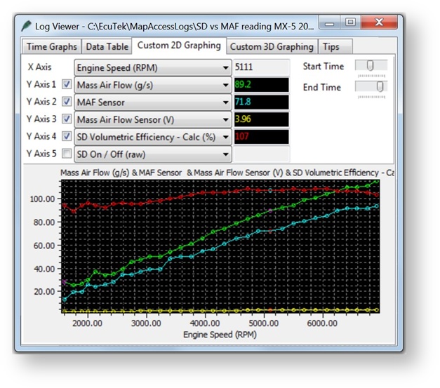
So by enabling SD we are able to LOG and SEE the affect the new Intake has had and we simply increase the 2D MAF scaling until the CYAN line meets the GREEN line, then turn OFF SD and we have a very close MAF scale!
NOTE: It’s very important that the MAP sensor scaling is accurate when using Speed Density.
Each sensor may be marginally different and you may find that a 3bar sensor is actually 3.15bar at 5volts so check with the manufacturer or compare it to the stock item by following this sequence:
- With the stock MAP sensor make a log file and check the Manifold Absolute Pressure with ignition ON (engine not running), and then at stable idle.
- Then fit new 3 or 4 bar MAP sensor and enter new scaling as above and repeat the test to ensure it’s the same manifold pressure with the Ignition ON (engine not running) and at Idle.
How to Rescale the MAP Sensor
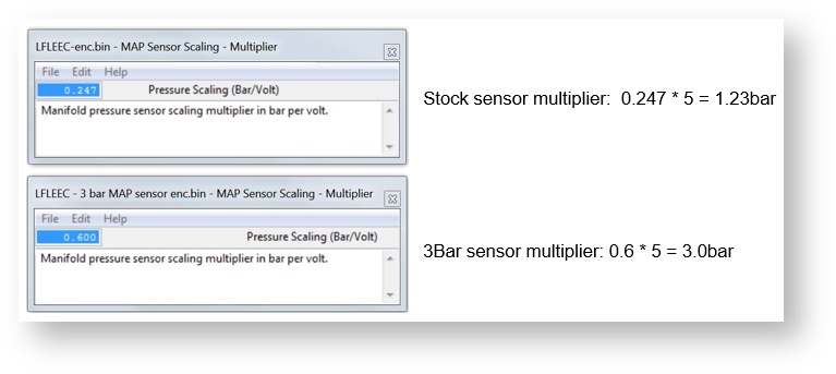
The factory MAP sensor can read to around 1.37bar absolute, we recommend that the MAP sensor is replaced on all Forced Induction models. A popular plug and play replacement is the VAG Bosch 3bar sensor.
The stock MAP Sensor Offset value is set to zero, the Multiplier value is 0.247, so 0.247 bar per volt with a 5 volt MAP sensor.
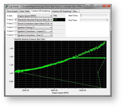
The screenshot below shows two log files that have been added together in excel.
The first log is with standard MAP sensor that flat lines at
1.37bar. The second log is a 3bar sensor that has been correctly rescaled.
The two lines are identical till 5400rpm where the stock sensor flat lines and but the 3bar continues to read the true manifold pressure until 7600rpm.
Map List
Live Data Parameters
- Barometric Pressure - Value of Barometric Pressure
- Barometric Pressure Sensor - Voltage output from Barometric Pressure Sensor
- Engine Coolant Temperature - Coolant temperature in degrees
- Engine Coolant Temperature Sensor - Voltage output from ECT Pressure Sensor
- Intake Air Temperature - Intake air temperature in degrees
- Intake Air Temperature Sensor - Voltage output from IAT Pressure Sensor
- Mass Air Flow - Measure of mass air flow in grams per second
- Mass Air Flow Sensor - Voltage output from Barometric Pressure Sensor
- Manifold Absolute Pressure - Manifold Pressure in Absolute PSI
- Manifold Absolute Pressure Sensor - Voltage output from MAP Sensor
Misc.
Exhaust Gas Recirculation
These maps change the desired Exhaust Gas Recirculation duty which affects the amount of clean air entering the engine. Altering the duty can significantly affect power and fuel efficiency by allowing more oxygen into the cylinders. It is also used for emissions regulations, and altering these maps can cause a vehicle to fail emissions testing.
Common Tuning Questions
I can’t find a RRFF for my ECU ROM ID
RaceROM Feature Files are only available for the latest ROM revision.
Denso are constantly developing, improving and bug fixing the ROMs so make the most of their hard work by using the latest revision.
Can my current map switch mode be remembered?
Yes the current map switch mode is remembered even if the battery is disconnected then the ECU will still remember the Map Switch Mode.
Can I have Launch Control or Speed Density in certain modes?
Yes, Launch Control, Flat Foot Shift and Autoblip are all configurable in any of the 4 modes, along with Speed Density.
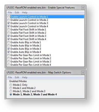
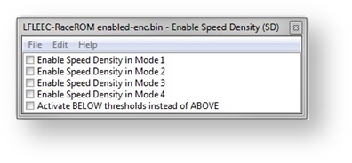
Can I switch between MAF and Speed Density on the fly?
Yes, you can enable or disable SD in any of the 4 modes. You can also use the Hybrid SD function in any or all of the 4 map switch modes.
Can I use launch control whilst driving?
No, you must be below a set vehicle speed for Launch Control to be enabled, the default setting is 8kph.
Can the dealer over flash my tuned ECU?
No, the dealer reflash tool (or other tuning tools) cannot over flash the ProECU tuned ROM. If you flash back a 100% stock ROM then any other tools can flash over the ECU.
What happens if I have a problem during programming?
If the vehicle interface become disconnected or the laptop powers off during programming then the ECU will be part programmed. ProECU can recover the ECU from this state by manually selecting the ECU from the TOOLS menu.
Can I log a vehicle if I haven’t programmed it yet?
Yes you can log any MX5 even if it has not been programmed with ProECU but any custom parameters (EcuTek ORIGIN) will not be displayed until the ECU is programmed with a RRFF applied.
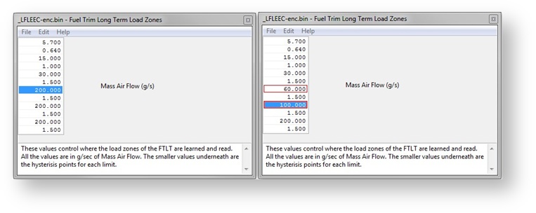
Can I stop full load Fuel Trims working in Open Loop?
Yes you there are two methods:
- Disable the map called Fuel Trim Long Term Operation Switch.
- Re-profile the FTLT load zones as shown below. This will ensure that learned FTLT in low load conditions are not applied at high load conditions.
EcuTek ProECU tuning tools tools should only be used by experienced tuners who understand the product and engine calibration.
If you do not fully understand this product then you WILL damage your engine, ECU or your vehicle.
Please ensure you fully read all EcuTek manuals BEFORE attempting to use ProECU with your laptop or your vehicle.
Use with extreme caution and understanding at all times, if in doubt then do not proceed.
EcuTek accepts no responsibility for any damage to the engine, ECU or any part of the vehicle that results directly or indirectly from using the product.
** If you are in any doubt that you do NOT have the experienced required to use this product then you should NOT USE IT **
Retail customers
** If you have any doubt that you do NOT have the experienced required to use this product then you should NOT USE IT, you should simply contact your EcuTek Master Tuner shown clearly on the top of your Programming Kit or visit your preferred tuning shop to have a professional tuner to use it for you **