GT-R RaceROM Tuning Guide
- Brandyn Mowat
- Michael Howard
- Lucan Hetherington
- Paul Blamire
Boost Gauge Rescaling
The boost gauge can be rescaled, and/or made to wraparound in order to display boost pressures in excess of the limitations of the standard gauge.
The Boost Gauge Rescale feature allows the tuner to rescale the boost gauge in order to accurately display the level of boost when it exceeds the normal factory scaling. Please note that it is not possible to change the numbers on the gauge at this time and this feature will NOT change Target or Actual boost values, only the boost gauge display will be rescaled.
Examples of boost gauge rescaling
Example 1
Boost Gauge Multiplier: 1
Boost Gauge Offset: -1.0
| Manifold Relative Pressure | Gauge Reading |
|---|---|
| 0.00 | -1.00 |
| 0.50 | -0.50 |
| 1.00 | 0.00 |
| 1.50 | 0.50 |
| 2.00 | 1.00 |
| 2.50 | 1.50 |
Example 2
Boost Gauge Wrap Threshold: 1.5
Boost Gauge Wrap Subtraction: 2.5
| Manifold Relative Pressure | Gauge Reading |
|---|---|
| -1.00 | -1.00 |
| -0.50 | -0.50 |
| 0.00 | 0.00 |
| 0.50 | 0.50 |
| 1.00 | 1.00 |
| 1.50 | 1.50 |
| 2.00 | -0.50 |
| 2.50 | 0.00 |
| 3.00 | 0.50 |
RaceROM Boost Controller (not to be confused with RaceROM Boost Control
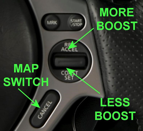
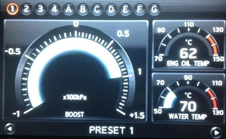
The RaceROM Boost Controller feature allows the driver to adjust the maximum desired boost using the cruise control buttons (when the cruise control is off). The boost level selected is displayed on the dashboard monitor.
- Ensure the cruise control is switched off.
- Press "RES/ACCEL" or "COAST/SET" to display the current desired boost.
- To increase desired boost by 0.1 bar, press "RES/ACCEL"
- To decrease desired boost by 0.1 bar, press "COAST/SET"
- To increase desired boost to maximum, hold "RES/ACCEL" for 2 seconds.
- To increase desired boost to minimum, hold "COAST/SET" for 2 seconds.
- After 2 seconds, the monitor display will revert to normal.
Configuration
The RBC feature operates as an upper limit on the desired boost. The feature will not increase the boost above the level set in the ECU desired boost map. For this reason, you must ensure that the ECU Desired Boost is set to the same or higher value than the RBC Max Boost. You should also set the Desired Boost Limit maps accordingly.
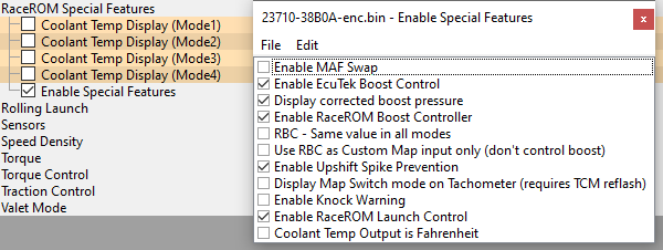
Enable Special Features
This map contains the checkbox to enable the RaceROM Boost Controller feature.

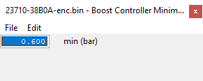
Boost Controller Minimum
This 1D map specifies the minimum boost level that the driver can specify.
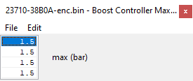
Boost Controller Maximum
This 1D map specifies the maximum boost that the driver can specify in each of the map switch modes.
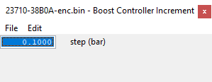
Boost Controller Increment
This 1D map specifies how much the boost is increased or decreased for each press of the button. By default this is set to 0.1 bar.
Per Gear Boost Control
The Per Gear Boost Control feature (Mode 1 to Mode 4) allows you to adjust the target boost based on Gear and RPM. This can be used to provide a higher boost level in lower gears for rapid acceleration while maintaining the standard boost level for cruising in the higher gears. The ECU will apply a multiplier to the Desired Boost based on RPM and Gear.
Integration with Map Switching Feature
Separate per Gear Boost maps are provided for each of the map switching modes.
Related Maps
Per Gear Boost Mode1,2,3,4
These maps define a percentage multiplier based on RPM and current Gear. The multiplier is applied to the ECU Desired Boost Table.
Clutch Slip Protection
To meet the increasing demands of higher and higher power levels being achieved on a reprogrammed factory ECU, we have added a strategy to adjust the power output to control and prevent clutch slip. This can be used to both impose a torque limit and/or retard the ignition to temporarily reduce power to halt clutch slip to acceptable levels.
This strategy will cater for instances where the TCM does not send a torque reduction request after a launch.
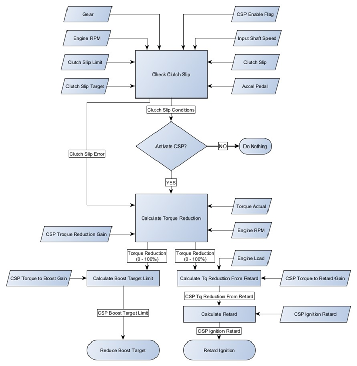
Operation
Once slip exceeds CSP Entry Slip for a time exceeding CSP Entry Delay then CSP becomes active and it reduces the power using ignition retard and reduced boost target. The strategy will try to bring the clutch slip down to CSP Slip Target and remains active until Clutch Slip drops below CSP Exit Slip for a time exceeding CSP Exit Delay.
The CSP Torque Reduction Gain map is used to change the overall torque reduction response to clutch slip, the CSP Torque to Boost Gain and CSP Torque to Retard Gain determine how that torque reduction is achieved, this is detailed below.
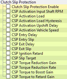
Map List
Live Data Parameters
- Clutch Slip (RPM) – Define as Engine Speed – Input Shaft speed in RPM. This can be negative as the engine speed increases to match shaft speed, typically on a downshift.
- Clutch Slip Error (RPM) – Difference between the current clutch slip and the target clutch slip, positive values mean more slip than desired.
- Clutch Slip Timer (Seconds) – Elapsed time that clutch slip has been over the limit while all other conditions for entering Clutch Slip Protection have been met. The timer stops once the timer reaches CSP Entry Delay.
- Clutch Slip Exit Timer (Seconds) – Elapsed time that clutch slip has been below CSP Exit Slip, the timer stops once timer reaches CSP Exit Delay.
- Clutch Upshift Timer(Seconds) – Elapsed time since an upshift was detected due to an increase of current gear.
- CSP Flags – Combination of flags used for diagnostic purposes by EcuTek
- CSP Ignition Retard (degrees) – Amount ignition timing has been retarded due to Clutch Slip Protection.
- CSP Boost Limit (Bar) – Boost Target Limit imposed due to Clutch Slip Protection.
- CSP Torque Reduction (%) - Current torque will be reduced by this percentage if CSP becomes active. Used as input on Y axis to Clutch Slip Retard
CSP Flags
1 = Outside upshift exclusion time
2 = Minimum slip condition met
4 = Minimum input shaft speed condition met
8 = Minimum load condition met
16 = Minimum Slip error condition met
32 = Minimum vehicle speed condition met
128 = Clutch slip control is active
Note: These values are displayed as a sum e.g. 3 = 1 +2 = Outside upshift exclusion time & Minimum slip condition met
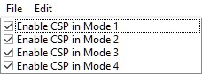
CSP Enable
Clutch Slip Protection measures can be enabled per Mapswitch mode and are enabled in all modes by default.
CSP Activation Load
Minimum engine load required to enable CSP intervention, raise this if CSP becomes intrusive at low load dealing with normal levels clutch slip encountered on some cars.

CSP Activation Load Hysteresis
Once CSP has been activated, the engine load must fall below (CSP Activation Load – CSP Activation Load Hysteresis). The default setting of this value results in CSP remaining active after some excessive clutch slip even if the load falls to a moderately low value. If CSP is generally too intrusive, better results may be obtained by dropping this to 20% load.

CSP Upshift Delay
Clutch slip will be ignored for this amount of time after an increase in current gear. This is used to ignore normal levels of slip during and shortly after a gearshift.
CSP Entry Slip
Clutch Slip needs to exceed this value for longer than CSP Entry Delay for clutch slip to be considered significant and CSP to be triggered, once triggered it will remain active until the slip drops below CSP Slip Target.

CSP Entry Delay
Clutch Slip needs to exceed this value for longer than CSP Entry Delay for clutch slip to be considered significant and CSP to be triggered, once triggered it will remain active until the slip drops below CSP Slip Target.
![]()
CSP Exit Delay
Clutch Slip needs to fall below CSP Exit Slip for this delay time for clutch slip to be ignored and CSP deactivated.
![]()
CSP Slip Target
Clutch Slip Error is defined as Clutch Slip – CSP Slip Target and once triggered, Clutch Slip Protection will remain active until Clutch Slip has dropped below CSP Exit Slip.

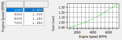
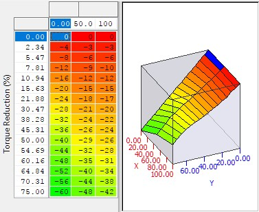
CSP Torque Reduction Gain
The level of torque reduction is dictated by the gain values in this map and the amount of unwanted clutch slip Clutch Slip Error which is defined as:
𝐶𝑙𝑢𝑡𝑐ℎ 𝑆𝑙𝑖𝑝 𝐸𝑟𝑟𝑜𝑟 (𝑟𝑝𝑚) = 𝐶𝑙𝑢𝑡𝑐ℎ 𝑆𝑙𝑖𝑝(𝑟𝑝𝑚) − 𝐶𝑙𝑢𝑡𝑐ℎ 𝑆𝑙𝑖𝑝 𝑇𝑎𝑟𝑔𝑒𝑡(𝑟𝑝𝑚)
The amount of torque reduction that results is calculated as:
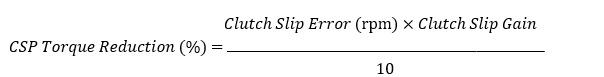
Therefore, a Clutch Slip Error of 200rpm, and a Clutch Slip Gain of 1.15 will result in a torque reduction of 23%
CSP Torque Reduction Rate
The top value is the limit to the rate at which torque can be reduced and the bottom value is the maximum rate at which torque can be raised. These values are used to prevent rapid oscillation of CSP Torque Reduction.
CSP Ignition Retard
A simple lookup table that returns an ignition offset (negative values retard the ignition) to reduce the torque based on the magnitude of CSP Torque Reduction This map should be adjusted to allow the retard to achieve the requested torque reduction. To alter the torque reduction overall changes should be made to CSP Torque Reduction Gain.
CSP Torque to Retard Gain
The torque reduction achieved using ignition retard is changed by altering this value, it multiplies the initial CSP
Torque Reduction value before it’s fed to the CSP Ignition Retard map. Using the default gain of 0.7 combined with a TQ Limit Gain value of 0.3 will result in 70% of the torque reduction coming from retard alone, while 30% of the torque reduction will be achieved by imposing a torque limit (which will close the throttle as required).
The Ignition Retard Gain and TQ Limit Gain values are intended to change the balance of torque reduction between
retard and a throttle base torque limit. If you are trying to tune the CSP and wish to change the overall torque reduction, then the CSP Torque Reduction Gain map should be adjusted.

CSP Torque to Boost Gain
The overall CSP torque reduction is used to reduce the boost to give a slower reacting but longer lasting torque reduction by lowering the boost target. The reduction in target Manifold Absolute Pressure is calculated as CSP Torque Reduction * CSP Torque to Boost Gain.
![]()
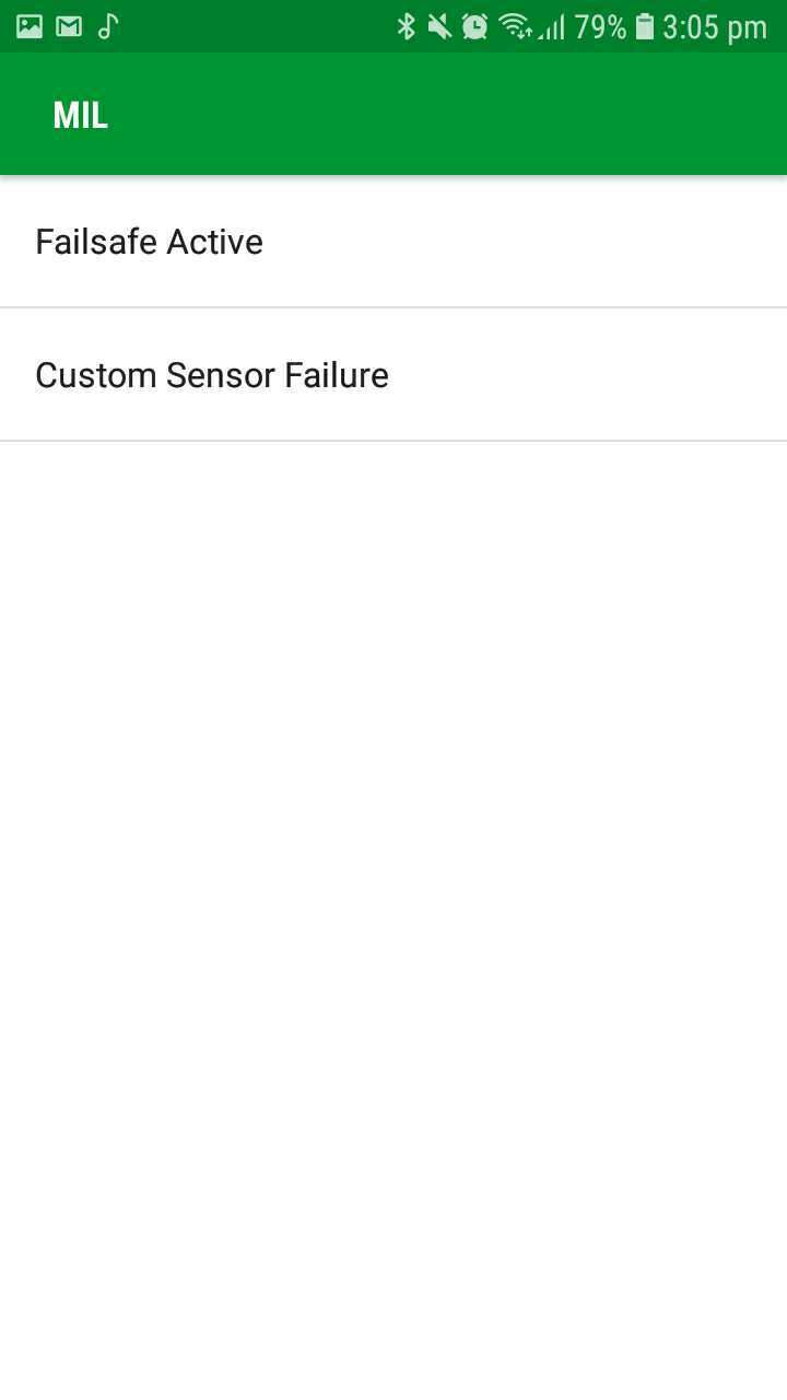
Check Engine Light (MIL) flashes and ECU Connect parameters
To improve diagnostics the MIL source parameter was added so that you know what the check engine light flashes are caused by. The following is a list of the numbers and outputs from the ProECU live data parameters.
| Value | Warning |
|---|---|
| 01 | Failsafe |
| 02 | Knock Warning |
| 04 | Clutch Slip |
| 08 | Custom Sensors (Voltage out of Range) Failure |
| 31 | All |
| 48 | Beta (reserved) |
| 64 | Live Tuning |
| 128 | Custom Maps Failsafe |
the ECU Connect page is Called MIL and displays the warning values as the text values above
12 Injector Support
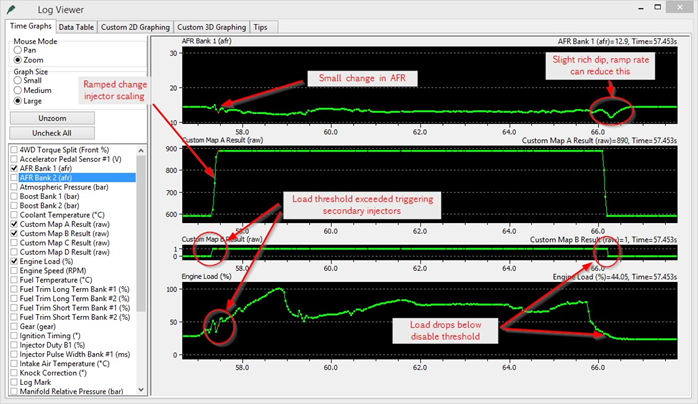
A simple but effective 12 injector strategy has been implemented that allows 12 injectors to be run on the GTR using additional hardware. Due to the limited spare outputs and the difficulty of fundamentally changing the low level scheduling of outputs, 12 injector support is achieved by switching a secondary bank of injectors on at low to moderate load while scaling the injector constant during a “ramp in” period. The secondary air solenoid is the only output currently available to use with this feature. Details on how to implement this are available on request.
Operation
The below screenshots shows the various stages of activating and deactivating the secondary Injectors
Map List
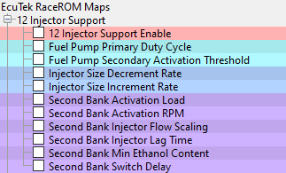
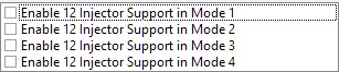
12 Injector Support Enable
12 injector support can be enabled in each map switch mode individually.
Fuel Pump Primary Duty Cycle
Direct fuel pump control is ONLY ENABLED WHEN 12 INJECTOR CONTROL IS ENABLED! So if you wish to use these maps, enable 12 injector control in all your map switch modes and set the enable RPM to 10000rpm so that it never comes on. Remember when 12 Injector Support is enabled the secondary air solenoid output will be hijacked.
Engine load is used rather than injector duty because when secondary injectors are active, the injector duty will change significantly. These fuel pump maps can be used to avoid such issues.
This map uses engine load vs final pump duty cycle and overrides the factory primary pump control strategy.
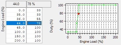
Fuel Pump Secondary Activation Threshold
The secondary pump control is still an on/off output but can be directly controlled with engine load.
![]()
Injector Size Increment Rate – Injector Size Decrement Rate
This controls how fast the injector scaling is changed. The units are cc/10ms so large changes in injector scale will need a larger number to make the change in the same time. 40cc/10ms proved a good compromise when testing with 300cc/min secondary injectors taking 75ms to ramp in and out. If using 1050cc/min secondary injectors, a ramp rate of 140cc/10ms will gave the same 75ms ramp time.

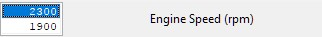
Second Bank Activation Load
The secondary injectors can be enabled above a specific RPM with hysteresis. Recommended activation is 20003500RPM depending on the turbo spool, and a 100-500RPM difference between activation and deactivation.
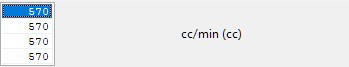
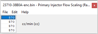
Second Bank Injector Flow Scaling
The secondary injectors are scaled in a similar way to the primary injectors in cc/min individually for each map switch mode and when enabled the primary and secondary injector scales are summed. When carrying out initial testing, it can be useful to use 3-4 different scales and map switch between them to test which setting gives the most consistent fuelling between 6 and 12 injectors.
Secondary Bank Min Ethanol Content
The ethanol content must exceed this value for the second bank of injectors to be activated. This function is designed to allow cars to run on the primary bank of injectors when running little or no ethanol and fuel requirements are significantly reduced.

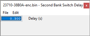
Second Bank Switch Delay
The delay value is used to prevent switching between 6-12 injectors with rapidly fluctuating load that is swinging beyond the thresholds. The thresholds need to be met for a time longer than the delay in order to actual switch between 6 and 12 injectors, when either activating or deactivating.
Large Injector Support
The standard ECU supports a maximum injector size of 800cc. RaceROM removes this limitation so you can fit larger injectors. RaceROM also offer different Injector size configurations for each of the 4 map switch modes enabling dual fuels to be used (example E85 the value could be decreased by around 25% therefore increasing each Injector open time period by 25%)
When using RaceROM Feature File Phase 3 or newer the factory Injector Flow Scaling map is not used anymore and should be ignored
Injector Flow Scaling (RACEROM)
This map is used instead of the normal Injector Flow Scaling map. Separate values can be specified for each map switch mode.
Ignition Timing (RaceROM Simplified)
timing strategy is very good when applied to a stock car but difficult and restrictive to tune for high power applications. RaceROM adds easy to use larger maps with high precision load input axis for improved control and range. Supporting maps are also added for further safety.
Some OEM maps are included here for convenience, but not all are covered in this guide yet.
Map List
Live Data Parameters
- Ignition Timing (°) – Current actual ignition timing in degrees BTDC, negative means ATDC
- Ignition Timing Calculated (°) – Ignition timing as calculated by the OEM strategy
- Knock Correction (°) – Offset due to knock, negative is retard, positive is dynamic advance on GEN 2
Ignition Timing Gear Comp
Ignition advance can be trimmed on a per gear basis, relative to RPM using this map. It would be normal to reduce advance in higher gears at high RPM or at an RPM sensitive to detonation.
Ignition Timing Comp Load Threshold
A load threshold under which the offsets in Ignition Timing Gear Comp and Ignition Timing IAT Comp are ignored.

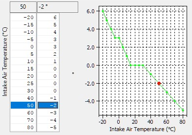
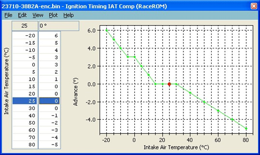
Ignition Timing AT Comp
An ignition timing offset based on Inlet Air Temperature which can be used to retard the ignition for high air temps. This is particularly useful on cars modified to put the IAT sensor in the low temperature boost pipe (after intercooler) as retard can be applied for charge temperature directly.
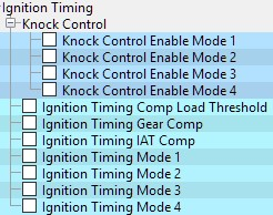
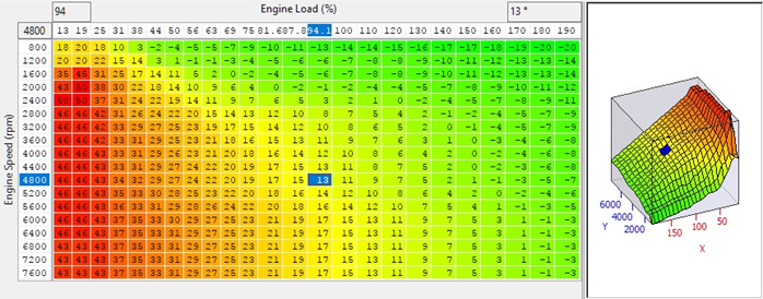
Ignition Timing Mode1(through 4)
Four maps, one for each mapswitch mode providing an easy to understand and tune base ignition value in degrees before top dead centre (BTDC). They provide increased precision and headroom for the load axis and increased RPM breakpoints. It’s possible to created multiple maps and use map switching to cycle between each map for testing. The numbers in these maps may not equal the final timing value as it will be subject to RaceROM corrections, knock control, dynamic advance, custom maps. These maps are not employed in overrun and idle conditions where the OEM ignition control is used.
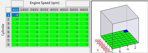
Ignition Retard Per Cylinder
A factory map which can be used to retard the ignition on cylinders especially prone to detonation. Through careful handling and using individual cylinder knock logging, this can gain small but useful amounts of power with no increase in engine risk.
Knock Warning
A simple driver warning for excessive knock control activity, flashing the CEL when triggered by knock retard. The ECU retards ignition timing when knock is detected. When the amount of retard exceeds the threshold, and increases further, the Check Engine Light will flash rapidly three times.
Map List
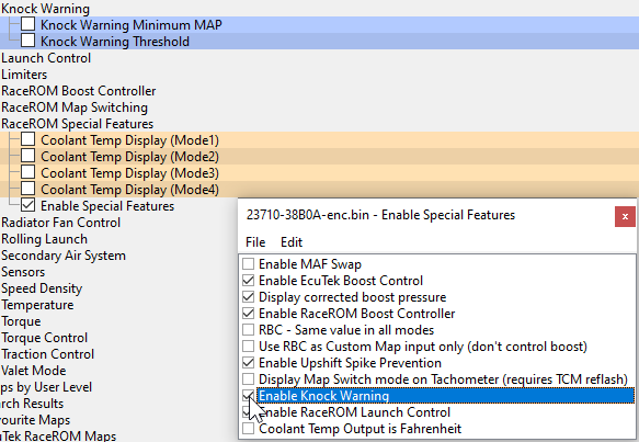
Enable Special Features
This Map contains the checkbox for the Enable Knock Warning feature.
Knock Warning Threshold
This 1D map holds the retard threshold in degrees that will trigger a warning.
Knock Warning Minimum MAP
The CEL will not be flashed while the Manifold Absolute Pressure is below this threshold. The default value of 1bar means the CEL will not flash while in in vacuum even if the knock retard is over the threshold.
![]()
Knock Warning Threshold
Knock retard which will trigger the knock warning.

Launch Control
The Nissan GTR has a built in factory Launch Control Mode, when conditions are correct this will deliver an extremely effective launch condition. When entering the special mode the throttle butterfly will react quickly providing a burst of Engine Torque which will load the transmission and drivetrain for a blistering launch condition.
This launch condition is often mistaken and confused for the typical ‘stall test’ launch that can be induced by on most Auto gearboxes models at the traffic lights (left foot on the Brake, Accel pedal to the floor and wait for the lights to change). This low torque/low RPM slipping convertor/clutch launch is not the same or nearly as aggressive as the special Launch Control Mode, though this type of launch is still very effective on the GTR when used.
From 2008 to 2013 each new version of the GTR had a revised launch behaviour, and these have been broadly categorised as LC1 to LC5 by EcuTek and its competitors. The LCx nomenclature is not official Nissan terminology, although some Nissan dealers will understand the term. There appear to be five different LC strategies, however there are not 5 distinct versions of TCM rom with different LC strategies, some ROMs use the same strategy with different map an data values resulting in different behaviour for the drive, some LC versions the result of different ECM maps.
For more information check out
MAF Bank Switching
The MAF Bank Switching feature allows you to correct the airflow measurement after fitting an aftermarket intercooler that swaps the airflow between the left and right banks of the engine. Some aftermarket intercoolers swap the airflow between the left and right banks of the engine having the air flow across the intercooler core, as opposed to the factory style where it loops back around to the same side throttle. This feature compensates for the mechanical alteration by swapping the MAF sensor readings between left and right banks.
Only check this box if the new Intercooler swaps the Intake flow between banks otherwise the ECU will be looking at the wrong throttle butterfly and wrong MAF sensor (for Mass Airflow reading) when controlling Idle and during Idle balance.
Enable Special Features
This Map contains the checkbox for the Enable MAF Swap feature.

Stock-Style AMS Intercooler
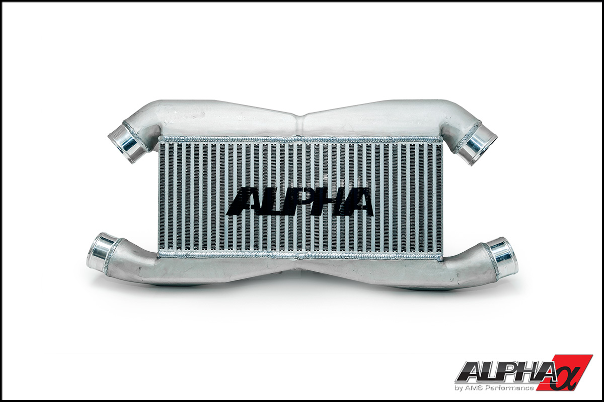
Greddy Cross-flow style intercooler

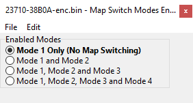
Map Switching
The Map Switching feature allows you to up to define four different calibrations in the ECU ROM. The driver can switch between the calibrations at the press of a button. It is envisaged that this feature will be used to provide a comfortable calibration for everyday road use and a hard-core maximum performance calibration for use at the track. Alternatively you could use this feature to provide four calibrations optimised for different grades of fuel.
The Map Switching feature is enabled by the Map Switch Modes option list in the RaceROM Special Features section. When this feature is operational, the ECU can be programmed with up to four different calibrations and the driver can switch between them.
You can optionally display a number for each mode on the coolant temp display, perhaps to remind the driver the octane level of fuel that this mode has been optimized for.
Switching between modes
The driver can select the map switch mode by holding down the cruise control "Cancel" button for 1 second when the cruise control is switched off.
The tachometer will move to 1000,2000,3000 or 4000, to indicate mode 1,2,3 or 4.
The mode number may optionally be displayed on the coolant temp gauge.
The driver can adjust the mode by using the cruise control Set/Cst and Res/Acc buttons. After selecting the desired mode, press “Cancel” again to save it.
Integration with other RaceROM Features
- Per Gear Boost Control Feature - The Per Gear Boost Control feature has separate maps for each of the four modes.
- RaceROM Boost Controller (RBC) Feature - The driver can set different boost levels for each of the four modes. The tuner can set a different maximum limit for each mode.
- Per Gear Rev Limits Feature - The Per Gear Rev Limits feature has separate maps for each of the four modes. The TCM will need to be in R-Mode to exceed 7000rpm gear change point.
- Large Fuel Injectors Feature - The Large Fuel Injectors feature has separate maps for each of the four modes. This can be used for multi-fuel set-ups like 92 Octane, 97 Octane, RaceGas and E85 in each of the four modes.
Mapswitch Modes
This map specifies how many map switch modes to enable.
Fuel Map Mode 1 (to 4)
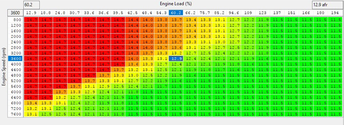
For each MapSwitch mode a RaceROM fuel map is used consisting of the base target AFR, and can be monitored by the live data parameter AFR Target Base. The target AFR from this map is subject to further changes by the stock Nissan ECU code and may not be the same as the final target used for the closed loop fuel control. For each bank the final target AFR can be monitored using AFR Target Final B1 and AFR Target Final B2.
The default values in this table give mostly stock AFR targets, thus this table if unaltered is conservatively rich if used on a heavily modified GT-R. If no changes to stock maps that adjust AFR targets are made, a target of 11.5 in this table will result in a AFR Target Final value of approximately 10.9:1.
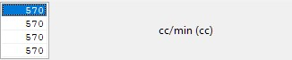
Injector Flow Scaling (RaceOM)
The injector flow rate can be calibrated per map switch mode. By default it assumes the stock injectors flow 570cc/min at the stock fuel pressure. You may been to make fine adjustments to these values different to the stated flow of aftermarket injectors due to assumptions used in the stock ECU code.
It is also possible to use 4 slightly different values in the process of tuning to quickly made adjustments without reflashing.
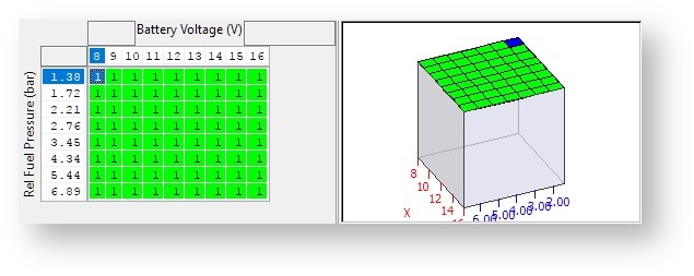
Injector Lag Time (RaceROM)
The OEM injector lag time (latency) is defined using a fixed voltage and a slope that gives accurate lag time over a narrow voltage range. It’s of limited accuracy, not very intuitive to set up and injector suppliers rarely give useable data for both lag time and slope. Instead, RaceROM now provides a 3D map using voltage and fuel pressure to allow complete control of the lag time. Best results will be obtained by using this in conjunction with a fuel pressure sensor so changes in flow and lag time can be properly corrected. It is only used when enabled in Injector Lag Time Enable for the current map switch mode.
If used without a fuel pressure sensor fitted to the car, this map can still be populated with values for the entire pressure range. Even without a fuel pressure sensor fitted (Custom sensor source set to "No Sensor") this map will use the default value defined in FP sensor default.
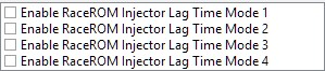
Injector Lag Time Enable
The use of RaceROM 3d lagtime table is entirely optional, and not enabled by default. If you wish to use the table, it can be enabled on a per MapSwitch mode basis.
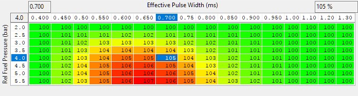
Injector Low PW Compensation
This table is used to make corrections to the INJECTOR FLOW RATE, so values above 100% will decrease the effective pulse width.
At the time of writing this is the opposite convention to many injector suppliers that give data for a percentage of correction to be made to the fuel pulsewidth.
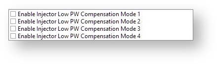
Injector Low PW Compensation Enable
The use of RaceROM Injector Low PW Compensation is entirely optional, and not enabled by default. If you wish to use the table, it can be enabled on a per MapSwitch mode basis.
Injector Low PW Compensation Max PW
When enabled the Injector Low PW Compensation is only active below this effective pulsewidth.

Injector Low PW Compensation Max RPM
When enabled the Injector Low PW Compensation is only active above this engine RPM.

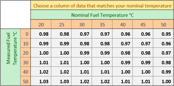
Fuel Temp Compensation
When tuning a car with a fuel temperature sensor, it is now possible to compensate for changes in the fuel temperature. Typically fuel pulsewidth is increased with increasing fuel temperature to compensate for the drop in fuel density, numbers greater than 1.0 will increase injector effective pulsewidth.
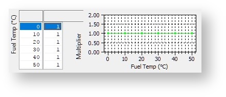
The table below outlines the approximate multiplier required to correct for a difference in fuel temperature.
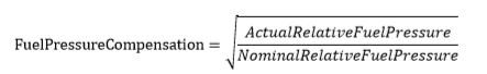
Changes in fuel pressure can be compensated for using this new map, in conjunction with an additional sensor configured using the new sensor options. For the purposes of this correction Relative Fuel Pressure is used and represents the pressure difference between the inlet (fuel rail) and nozzle (inlet port) pressures, defined as:

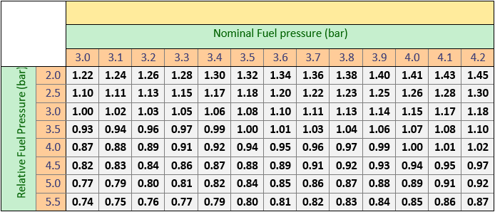
The below example is shown using a nominal fuel pressure of 3.5bar (50.75 psi)
This is demonstrated in the graph below showing that while the pressure in the fuel rises with manifold pressure the relative pressure remains consistent, only varying due to the limits of the regulator when the second pump activates.
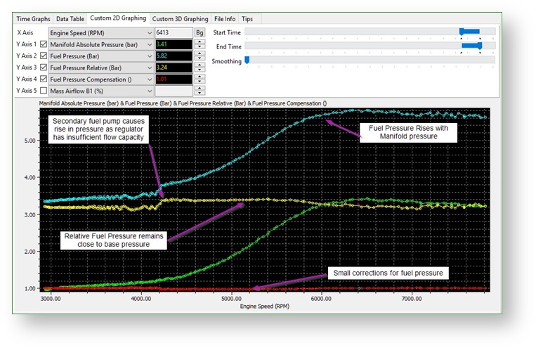
At close to sea level with an atmospheric pressure of 1.0 bar this would result in a relative fuel pressure of 3.6 bar if the Gauge Fuel Pressure was 4.9 bar at 2.3 bar MAP (1.3 bar relative boost).
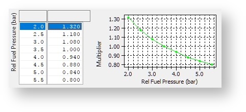
Within the normal range of fuel pressure the injector pulsewidth should be multiplied according the following approximation.
Below are examples of how to populate this table for common base fuel pressures in bar
Coolant Temp display during Map Switch
The four ignition maps can be calibrated for different fuel, in addition we can change the values shown on the Coolant Temp Gauge during Map Switch Mode to indicate the fuel currently in the fuel tank.
| Map Switch Mode | Coolant Temp Gauge Display | Sugesting Fuel Type |
|---|---|---|
| Ignition Timing Mode1 | 95 | 95 RON |
| Ignition Timing Mode2 | 98 | 98 RON |
| Ignition Timing Mode3 | 106 | 106 Octane Race Fuel |
| Ignition TIming Mode4 | 85 | Ethanol Based Fuel (E85) |
Default values shown on the Coolant Temp display when Map Switching
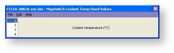
Example values that could be shown on the Coolant Temp display when Map Switching
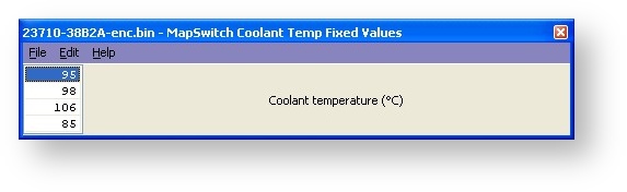
When MODE 1 is selected the Coolant Temp gauge will show 95 (203F)
When MODE 3 is selected the Coolant Temp gauge will show 106 (228F)
NOTE: The units are in Deg C (Celsius) but on US models the values will be displayed in
Fahrenheit . So you will need to reduce the Deg C values so the correct Fahrenheit value is shown on the display. Google offers a simple online conversion.
In addition by using the Rev Counter tacho indication for Map Switch Mode then we still have a visual indication of Modes 1 to 4 (requires TCM programming with the latest RRFF version for Tacho Indication).
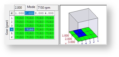
Per Gear Rev Limits
Easy to use rev limiter that employs a 100% fuel cut with hysteresis. Calibratable based on Map Switch Mode and Gear.
The Per Gear Rev Limits features allow you to define different rev limits for each gear. By setting a higher rev limit in lower gears you may be able to reduce the number of gearshifts required in attaining a given speed. E.g. 0-60mph or 0-100km/h tests.
To simplify the setting of the fuel cut based rev limits, they now all appear in one 3d map and use a single 1d value to introduce hysteresis. The fuel cut will be active over the RPM value in this map, and fuel will only be restored when the RPM has dropped below this level by Rev Limit Hysteresis.
Be aware that GEN2 cars typically have a 7300rpm fuel based rev limit so you may wish to raise the defaults in this map to match the stock limit.
Rev Limit Hysteresis
Hysteresis value used when Rev Limit Per Gear has been triggered.

Sensor Scaling & Custom Sensors
Custom sensor inputs have been added for fuel pressure and coolant pressure, and extra functionality has been added to the existing FlexFuel sensor input, which now falls under the Sensors category with all the OEM and RaceROM sensors.
- Coolant Pressure – Coolant pressure (gauge) in bar
- FlexFuel Ethanol Sensor Output – Ethanol content as reported by the sensor output, including filtering
- Fuel Pressure – Total Fuel Pressure in bar (gauge) at the point of measurement
- Fuel Pressure (relative) – Filtered pressure differential across the fuel injector used for compensations and safety trips, also available as an input for custom maps. Correct values rely on the use of a fuel pressure sensor that returns gauge pressure (almost all do).
Map List
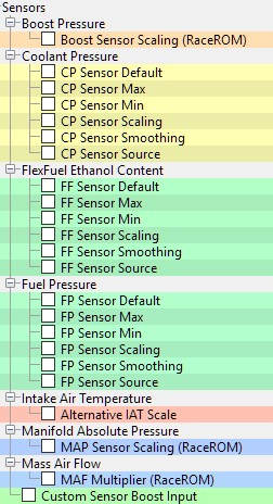
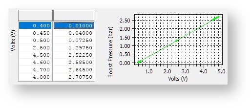
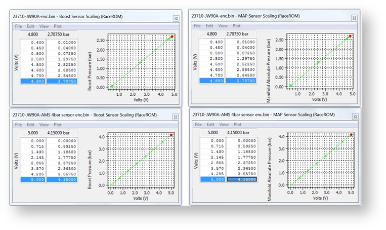
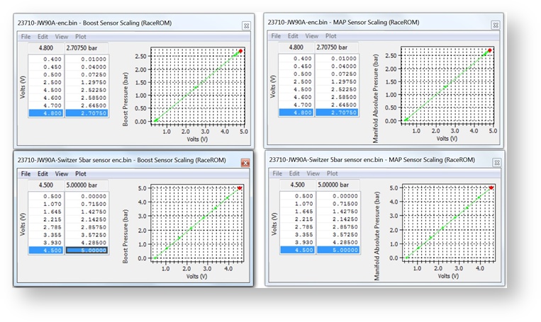
Boost Pressure Sensor Scaling
The stock scaling for the boost sensors can be replaced. However at the current time it’s use is depreciated as there are some OEM strategies that use the raw voltage, resulting in odd behaviour if a pair of 4 bar sensors are used.
Custom Sensor Inputs
Due to the identical nature of each of these sensors, the common maps are only described for the fuel pressure sensor, but the same functionality applies to all the custom sensors.
FP Sensor Default
If the sensor voltage is below FP Sensor Min or above FP Sensor Max, the sensor will be considered to have failed and the default value will be returned. Typically, sensors will give a useful output over a range a little less than their full-scale output so that faults can be diagnosed. For example, many pressure sensors will output between 0.5 and 4.5 volts, and voltages significantly outside this range would indicate an error. Aftermarket FlexFuel sensors that output 05v outputs however, normally use a full 0-5v range so the limits for a FlexFuel sensor should be set appropriately for example a minimum of -1v and a maximum of 5.1 volts.
In the case of the fuel pressure sensor the default value is employed by all maps that use Rel Fuel Pressure as an input. Adjust the default value to match your actual fuel pressure as required.

FP Sensor Max
Maximum nominal voltage expected from the sensor, over which a fault will be assumed and the FP Sensor Default value returned. This can be set to a high value such as 6 to never trigger a failure.

FP Sensor Min
Minimum nominal voltage expected from the sensor, below which a fault will be assumed and the FP Sensor Default value returned. This can be set to a negative value such as -1 to never trigger a failure.

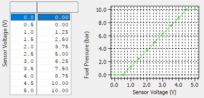
FP Sensor Scaling
Sensor output based on input voltage.
FP Sensor Smoothing
This is an exponential filter, as implemented the filtered value is returned as a weighted average of the new value and the value from the last cycle, thus:
𝑁𝑒𝑤𝐹𝑖𝑙𝑡𝑒𝑟𝑒𝑑𝑉𝑎𝑙𝑢𝑒 = (𝑁𝑒𝑤𝑅𝑎𝑤𝑉𝑎𝑙𝑢𝑒 ∗ 𝑆𝑚𝑜𝑜𝑡ℎ𝑖𝑛𝑔) + ((1 − 𝑆𝑚𝑜𝑜𝑡ℎ𝑖𝑛𝑔) ∗ 𝐿𝑎𝑠𝑡𝐹𝑖𝑙𝑡𝑒𝑟𝑒𝑑𝑉𝑎𝑙𝑢𝑒)
Lower filtering values give smoother sensor values, smoothing value of 1 gives no filtering, smoothing value of 0 will result in the sensor output always being 0.
You can select the source for custom sensors, however there are some caveats surrounding some of these choices and they should be considered with care. If you want to re-purpose an input

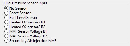
FP Sensor Source
- No Sensor - This will not use the custom input, and the default value will be returned. There is an exception to this when looking at fuel pressure inputs, in that the default value will be presented as the relative fuel pressure instead of the gauge pressure which is used in the sensor scaling.
- Boost Sensor - This is one of the preferred options for sensor input and can be the easiest for fuel pressure or FF due to ease of access. It needs to be used with the option specified in Custom Sensor Boost Input which selects which bank’s boost sensor input your custom sensor is physically connected to.
- Fuel Level Sensor - For a very few cars this may be applicable, for example in the case of an aftermarket race fuel tank being fitted and the OEM tank removed.
- Heated O2 sensor 2 B1/B2 - USE WITH CAUTION. These can be used but can introduce problems. Use of these may introduce problems with the front o2 sensor readings and require regular ECU resetting to clear the A/F Adjustment Bank #1 / #2 sensor learning that may build up.
- MAF Sensor Voltage B1 / B2 - This is another good option for sensor input on cars that have been converted to Speed Density. There are no real restrictions when using MAF inputs but be sure to disable appropriate DTCs and/or adjust min/max voltage levels.
- Secondary Air Injection MAF - This is one of the easiest and lowest risk options for sensor input and may require some DTCs disabling if your input is likely to reach 0v or 5v.
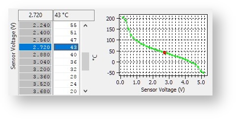
Alternative IAT Scale
In the stock implementation, the Intake Air Temperature sensor shares it’s scaling data with the engine coolant temperature. If replacing the IAT sensor, it’s possible to use the RaceROM scaling instead to cater for non-standard scaling without disrupting the ECT sensor scaling. Use of this scaling map is enabled in Speed Density»SD Enable.
MAF Multiplier (RaceROM)
In previous versions of RaceROM larger MAF housings could be catered for by changing the OEM conversion from MAF load to airflow. However, it was found that at some stages of the airflow calculation, the scaling of large MAF housings caused some internal low precision variables to max out, and irregularities to occur in the load and airflow.
MAF Multiplier (RaceROM) can be used to multiply the measured airflow in line with the relative change in the MAF cross sectional area. All calculations are carried out using high precision numbers and there is no loss of accuracy as a result. Typically, a 76mm MAF housing will work well with this set to 1.33. Do not adjust the stock value in MAF Sensor Scaling (% to g/s) for Load when using this, otherwise the load will be adjusted twice.

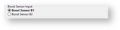
Custom Sensor Boost Input
If any of the custom sensor inputs are configured to use “Boost Sensor” as their source, the appropriate sensor must be selected here. If any sensor is configured to use “Boost Sensor” the voltage from the non-selected sensor is copied to redundant sensor input.
For example, if “Boost Sensor B1” is selected the follow should happen:
- The custom sensor will use the sensor input from B1 boost sensor.
- The B2 boost sensor input will be copied to the B1 Boost sensor.
- Both B1 and B2 boost values will get their value from the B2 sensor which is still connected.
By using the RaceROM Hi Boost map feature we can increase the boost to 3 bar+.
There are 3 MAP sensors fitted to the GTR and they are all 2.83 bar absolute sensors.
One MAP sensor is located in the plenum (Inlet manifold) and can show manifold vacuum, this MAP sensor is used for RaceROM Speed Density and the also the Boost Pressure display on the driver information display.
The other two MAP sensors are fitted pre throttle (one in each bank) and they are used for boost control and boost limit.
Any vehicle running more than 1.7bar boost will need 3 x new MAP sensors fitting pre and post throttle to be able to control boost pressures over 2.70bar absolute using the factory boost control system.
But if Custom Maps is used for boost control (where the plenum based MAP sensor can be used for the pressure reading) then the two pre throttle MAP sensors do not need to be replaced and the boost control can be based on the plenum based MAP sensor.
But please note that the boost limit is based on the pre throttle MAP sensors and if they are still stock items (2.83bar) then the boost limit will never trip with values greater than 2.7bar in the map. In this case you can create a custom map for fuel cut against the Inlet Manifold based MAP sensor.
Multiplier (bar/volt): 0.613
Offset (bar): -0.235
0.613bar x 5 volt = 3.065bar
3.065bar – 0.235bar Offset = 2.83bar (for the standard MAP Sensors)
Multiplier (bar/volt): 0.83
Offset (bar): 0
0.83bar x 5 volt = 4.15bar
With zero Offset value the AMS sensors are rated at 4.15bar Absolute.
As you can see its possible to calibrate the input voltage values as well as the output pressure values.
Intake Air Temp compensation
The Intake Air Temp (IAT) compensation map is used to add or retard ignition timing for a given IAT. This is very useful for Charge Air readings (if a Nissan Juke type boost sensor with integrated air temp sensor is used). In this situation then IAT reading is actually Charge Air (post intercooler).
We have fitted and tested a very nice ‘plug and play’ charge air conversion kit where the Intake air sensor is substituted by the new replacement boost sensor that incorporates Charge Air temp.
This is a great solution for Speed Density conversions, contact Got Boost Performance for more info.
TCM Tuning
The Nissan GT-R TCM is at the heart of the GT-R driving experience and delivers excellent control of the Ricardo 6 speed dual clutch transaxle. The TCM controls the pressure applied to both of the clutches in the gearbox, while accurately positioning the selector forks to select gears in two gear clusters. The TCM is tightly linked to the ECM and together they deliver much of what makes the GT-R driving experience what it is.
An in depth understanding of the GR6 transmission can be had by comprehensive reading of the Nissan technical service manual that describes the mechanical operation, and many diagnostic functions and information. For detailed service and diagnostic information please refer to section TM “Transaxle & Transmission” in the Nissan R35 GTR service manual.
Some aspects of operation are useful to know in the tuning and calibration of the TCM maps to improve the driveability and/or performance to compliment power upgrades and transmission hardware changes. Understanding the live data and how to interpret it is an important step in successfully tuning the TCM.
For additional information check out the GT-R TCM Tuning Guide
Torque
Introduction
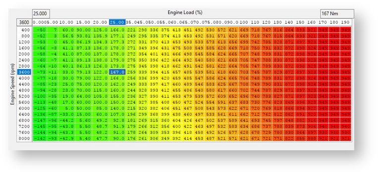
The GT-R uses torque extensively for interacting with the TCM and VDC systems, but the 16x16 OEM map used as the basis to calculate torque only accommodates with load values up to 100% which can be exceeded by a stock car running increased boost. To overcome this issue RaceROM adds a new 26x19 map that uses a high precision load input that allows any load value to be used. This gives more accurate torque values at low loads while catering for torque values that can increase with engine loads seen on 1500hp cars.
It is important to understand that torque is derived from load, which is an expression of estimated airflow, so proper operation of the torque model relies on accurate tuning of the MAF or SD and injectors. Errors in the resulting torque of just 10% can give poor shifting feel, so efforts need to be made to ensure that errors in injector scaling are not covered up by poorly calibrated MAF or SD VE maps, or vice-versa.
Torque Actual (RaceROM)
The default values are calibrated to give results that offer as close to stock behaviour as possible within the range of the stock map. The areas most likely to benefit from fine tuning are in the part throttle zones, and even on cars which have well calibrated fuelling and airflow, tuning this can be of benefit to iron out some odd TCM behaviours.
This map should not however be used as a band-aid to fix a general trend of slipping clutches. Specific tuning of the TCM should be used on cars that have issues holding the peak torque the engine can deliver.
Map List
Live Data Parameters
- Torque Actual – Final Torque actual value after compensations, usually different to values in map
Upshift Boost Spike Prevention
When the vehicle shifts into a higher gear, the sudden reduction in engine RPM can cause a momentary but substantial increase in boost pressure. The Upshift Boost Spike prevention feature can help to prevent this spike by reducing wastegate duty during the shift. (see screenshot below for a before and after comparison). This problem is exaggerated at higher boost pressures and also with larger turbo’s fitted.
Larger turbos will take long to respond than the stock turbos.
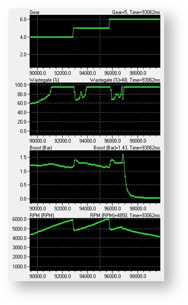
Without USP - Spike to 1.43bar
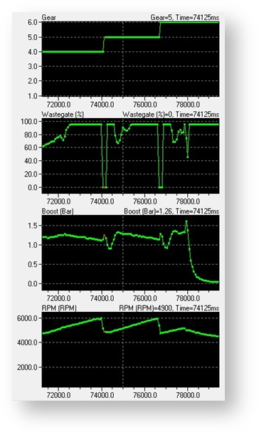
With USP - Spike reduced to 1.26bar
Enable Special Features
This map contains the Enable Upshift Spike Prevention checkbox to enable this feature.

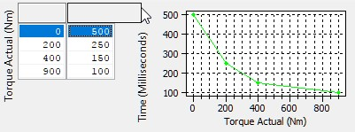
USP Wastegate Multiplier
This 3D map allows you to specify a multiplier for the wastegate duty based on the current boost pressure and the time period after the gear change in milliseconds (ms). The wastegate duty will be multiplied by this value during/after an upshift has been performed.
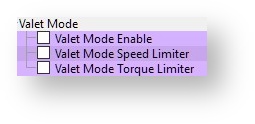
Valet Mode
Introduction
Valet Mode allows the driver to lock the car into a lower performance mode when lending it to a less experienced driver, or as a theft deterrent that kicks in when the car is at a safe distance. Valet mode has been simplified in line with the strategy used on the 370z, as the previous version was frequently commented on as being too complicated to activate and deactivate. Valet mode is operated using the cruise control switches in the same way as map switching. Instead of selecting map switch mode 1, 2, 3 or 4, select mode 8. The map switch mode does not change.
Map List
To turn on the Valet mode
- Ensure that the cruise control is OFF.
- Hold the CANCEL button for 1 second.
- The rev counter will move to indicate the current mode.
- Use the cruise up button until the tachometer shows 8000rpm (mode 8).
- Press CANCEL or wait 1 second to enable the valet mode, the rev counter will show current RPM
To turn off the Valet mode
- Ensure that the cruise control is OFF.
- Hold the CANCEL button for 1 second.
- The rev counter will move to indicate the current mode.
- Use the cruise up button until the tachometer shows 8000rpm (mode 8).
- Press CANCEL or wait 1 second to enable the valet mode, the rev counter will show current RPM
Please take note that Valet Mode activation is now a toggle and it’s relatively easy to activate. Car owners can in some cases activate it accidentally and it’s not been unknown for car owners to end up at a main dealer to have their “problem” fixed!
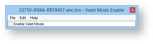
Valet Mode Enable
The "Enable Valet Mode" checkbox enables operation of the Valet Mode feature.
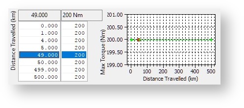
Valet Mode Torque Limiter
When Valet Mode is active the torque output can be limited to prevent a car being driven hard or recklessly. For use as an anti-theft measure it would be reasonable to reduce these values from the default 200Nm after a short distance.
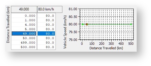
Valet Mode Speed Limiter
When Valet Mode is active the maximum speed can be limited to prevent the car from being driven at anything beyond a sedate pace. For use as an anti-theft measure it would be normal to significantly reduce these default values to as low as zero after a shorter distance.
FAQ
Which TCM ROM should I use ?
We recommend that the LC5 TCM called ‘32085-KJ10BDA-RRFF 12771 Rev Counter Map Switch Enabled LC5 enc.bin ‘ is used in all TCMs (even if the ECM has not or will not been programmed with ProECU).
When should I use Speed Density ?
You should only need to run SD if the MAF sensor are maxed out, this will be 600bhp on stock 66mm MAF tubes and 850bhp on 76mm MAF tubes. You can use SD to develop a MAF calibration for larger intakes.
When should I use Hybrid Speed Density ?
Hybrid SD is a great solution if your MAF volts are hitting 5volts at a higher RPM. In this situation you can run the superior MAF load input and only switch to SD when the MAF is nearing 5 volts. See the Hybrid SD section for more details
What Engine Load should I expect to see
Stage1 and 2 typically hit around 100% to 110% at 1.2bar boost, 1000bhp cars are hitting around 200% Engine Load at 2bar boost, You can rescale the X axis for over 180% Engine Load. This is running on MAF , but the Engine Load will be lower when running on the MAP based SD calculations.
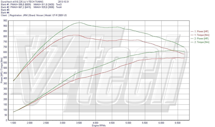
How much extra power can I get on E85 ?
On a typical stage1/2 setup we see about +60bhp, with further gains on a high power vehicle.
The example below shows a power increase from 600bhp to 670bhp along with a torque increase from 810NM to 930NM, running stock turbo’s.
Can I calculate the Engine Power Output ?
The maximum Mass Air Flow reading in grams can be used to calculate the theoretical engine power output (assuming a standard air Intake Tubes is still fitted). By multiply the Mass Airflow by 1.25 we can get a rough engine power output. So a peak Mass Air Flow reading of 200 grams at 7000rpm would be calculated as 250BHP. On Nissan GTR there are two MAF sensors and the output should be added together to calculate power output.
Standard GTR develops around 190 grams Mass Air Flow at peak power, so 190 x 2 = 380grams X 1.25 = 475 (BHP). This works on most engines but does depend on the engines design and efficiency, it can also works on naturally aspirated engines.
The car is not smooth on gear changes.
Ensure you have the LC5 TCM ROM installed and use the latest RRFF phase 3 (12738) or newer installed, the phase 3 provides incredible smoothness and driveability. Also ensure on Gen 1 cars that you are running the JW series ROM.
The clutches slip on full load
It’s critical that the Fuel Trims are within +/-10% so that the Engine Torque value sent to the TCM is accurate. If it’s too low the clutches will slip, watch the Clutch Slip logging parameter in the TCM ROM. Make a log of the TCM during a full load run, the maximum clutch pressure is normally 16.5 to 17.2bar, the clutch seals cannot hold more that this during our testing. See section 7 for advise on adjusting the Torque Actual map to avoid the clutches slipping.
Why doesn’t Race ROM Launch Control work?
Ensure coolant temp is over 70 deg C, ensure your TCM ROM has RRLC enabled in the mode you are using. Also see the Launch Control section for more help.
The car doesn’t launch well
If the car bogs on launch or just after launch then make a TCM Learning sequence then adjust the clutch capacity and touch points as per the Special Tools section later in the manual. Too much clearances on the touch points can cause this.
Why doesn’t Rolling Launch work?
Ensure the RRRL feature is enabled for the current selected mode , ensure the Cruise Control is enabled and set to a specific speed then press full throttle, see the RRRL section for full instructions.
Using Rolling Launch I sometimes get a P0605 DTC
If the RRRL feature is enabled we advised to disable all P0605 DTCs, these DTCs can occasionally occur on some models at random times, just turn the P0605 DTC off to avoid this potential problem.
I cannot get the Idle Learning or Gearbox Learning to work
Ensure the oil temps are hot, if bigger MAF tubes are fitted then try adding plus 5% to the MAF scale in the Idle region , there is a minimum airflow g/sec required for the learning sequence to commence.
The Idle is not smooth or stable after programming
Make sure you make an ECU Reset after programming either ECU and also carry out the Idle Airflow Learning sequence.
If you have fitted larger injectors ensure you reduce the Minimum Injector Open Time.
If you have fitted MAF Tubes then Enable SD to see if the Idle improves and the MAF tubes are causing the problem.
Check the Throttle voltage between Bank #1 and Bank #2
Check for Dump Valves sticking open at Idle
I get an error message trying to program the ECM or TCM
The engine should not be running and in PARK, also ensure headlights and interior fan blower are off, see the ECU programming section for further advise.
I get Torque error DTCs when pulling away or driving
Ensure you are running RRFF phase 3 or newer.
Ensure the K Factor values are stock (as K Factor will distort the engine torque values given to the TCM). See the previous Idle stability questions as well.
Some aftermarket BOV with strong springs can cause this.
Try enabling Speed Density as a test to help you understand the problem.
Typical Power Gains
Here are some example power gains that can be achieved with ECU tuning:
EcuTek ProECU tuning tools tools should only be used by experienced tuners who understand the product and engine calibration.
If you do not fully understand this product then you WILL damage your engine, ECU or your vehicle.
Please ensure you fully read all EcuTek manuals BEFORE attempting to use ProECU with your laptop or your vehicle.
Use with extreme caution and understanding at all times, if in doubt then do not proceed.
EcuTek accepts no responsibility for any damage to the engine, ECU or any part of the vehicle that results directly or indirectly from using the product.
** If you are in any doubt that you do NOT have the experienced required to use this product then you should NOT USE IT **
Retail customers
** If you have any doubt that you do NOT have the experienced required to use this product then you should NOT USE IT, you should simply contact your EcuTek Master Tuner shown clearly on the top of your Programming Kit or visit your preferred tuning shop to have a professional tuner to use it for you **