Mazda MX-5 RaceROM Supplement
- Brandyn Mowat
![]()
Mazda MX-5 RaceROM Tuning Guide Supplement
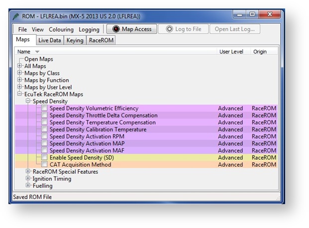
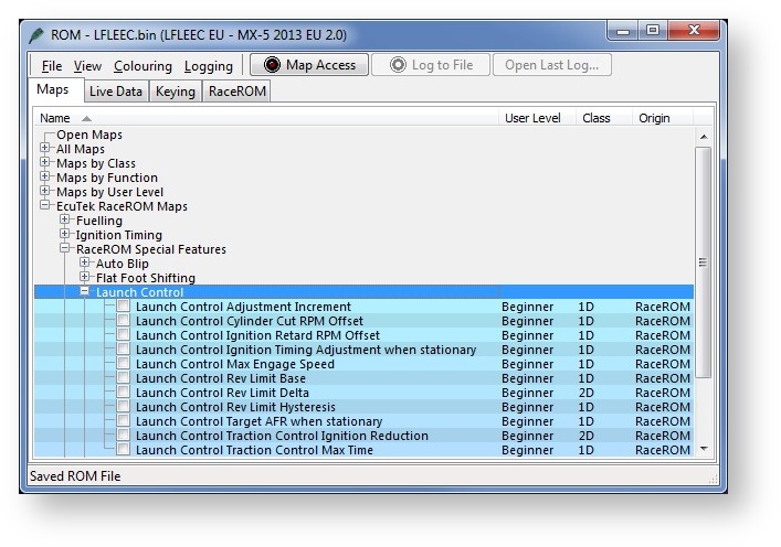
To see all of the RaceROM maps for your platform. Expand the "EcuTEK RaceROM Maps" folder.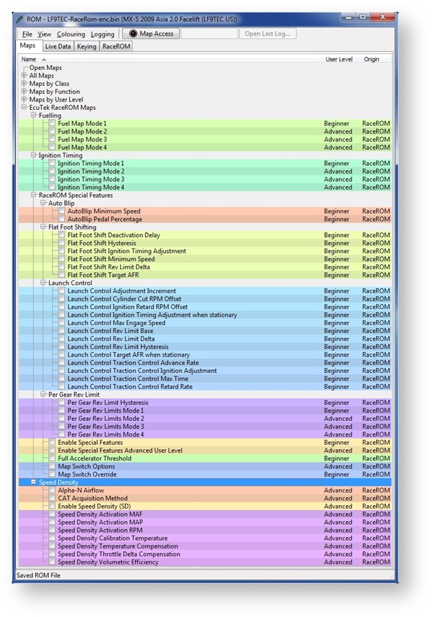
Map Switching
The Map Switching feature allows you to define four different calibrations in the ECU ROM. The driver can switch between the calibrations using the cruise control lever. The Map Switching feature can also be used as a trigger to activate other RaceROM features. For example: the Launch Control, Flat Foot Shift and Auto Blip features can each be configured to operate in any of the four modes. Map state can be logged under the live-data parameter "Mapswitch Mode"
The Map Switching feature is enabled by the option buttons in the ‘Map Switch Options' map. Four modes are allowed by default, but this can be reduced if desired. In “Mode 1”, the ECU will use the original ECU maps for Fuelling and Ignition Timing if the option is enabled. In the other three modes, the ECU will use the new Fuel, and Ignition Timing maps labelled Mode2, Mode3 and Mode4 as appropriate. 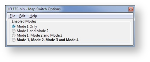
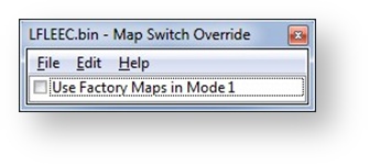
Map Switch Override
There is an option to disable the RaceROM Maps in Mode 1 to retain the factory fuel and ignition strategy.
Switching Mode Using the Cruise Control Instruments
- Ignition must be ON
- Ensure cruise control master switch is OFF
- Press the cruise control cancel button on the steering wheel.
- The tachometer will move to 1000, 2000, 3000 or 4000 rpm to indicate the currently active mode.
- Move the cruise lever up (res/acc position) to increase the mode.
- Move the cruise lever down (set/cst position) to decrease the mode.
- Save the selected mode by pressing the cancel button again or waiting 2 seconds.
The last selected Map Switch mode will be saved when the vehicle is turned off, so when you restart the engine it will default back to the last selected mode.
Speed Density
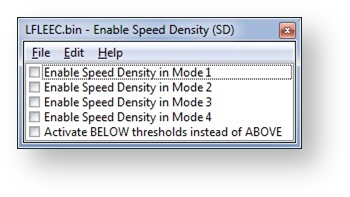
The Speed Density (SD) feature changes the way that mass airflow is calculated. When SD mode is activated, the ECU will disregard the MAF sensor reading and calculate mass airflow based on Engine Speed, Manifold Pressure and Air Temperature instead. This allows you to remove the MAF sensor and fit a larger intake if desired. The feature is enabled by selecting the checkbox in the Speed Density Enable map. The Speed Density Feature can be enabled in any of the four calibration modes by selecting the appropriate checkboxes in the “Enable Speed Density (SD)” map. It can also be toggled within the map switch modes, however there is only one set of speed density maps.
When this feature is active, the ECU will ignore the reading from the Mass Airflow sensor and will calculate mass airflow as follows:
- Estimated mass airflow is calculated from RPM, Manifold Pressure, Charge Air Temperature, and Volumetric Efficiency (VE), output from the Speed Density Volumetric Efficiency (Speed Density Volumetric Efficiency) map.
- This value is then multiplied by an adjustment factor selected from the 2D “Speed Density Temperature Compensation” map based on Intake Air Temperature.
- This is then multiplied by a value selected from the 2D "Speed Density Throttle Delta Compensation" map, resulting in a mass airflow value in grams/second.
The state of the SD system can be monitored in Live Data using the “SD Active” parameter. (0 for Off, 1 for On). The “SD VE Actual” parameter will display the output from the SD VE map, or 0 if the system is not active. The “SD VE Calculated” parameter provides a theoretical value for volumetric efficiency based on Mass Air Flow, Intake Air Temperature, Engine Speed and Manifold Relative Pressure, helpful when calibrating the SD VE Map.
This is a MAP sensor based load input into the ECU (compared to the more forgiving factory MAF sensor based load input).
In certain situations Speed Density is more suitable over a MAF based input, these are usually:
- The air speed through Large MAF tubes is too slow to accurately measure for a stable Idle
- Turbo compressor wheel causes reverberations up the intake pipe and upset the MAF sensor reading
- Turbo installs use Vent-To-Atmosphere Blow-Off Valves (BOV’s) instead of a preferred recirculating design.
- Supercharger re-circulation valves cause reverberations up the intake pipe and upset the MAF sensor reading
- The stock MAF is flat lined at 5 volts and cannot read any higher than the 5 volt limit (where ideally a slightly larger MAF tube should be fitted like 69 to 76mm)
In these situations the Speed Density or Hybrid Speed Density can be used.
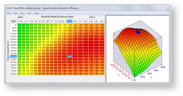
The SD VE map is against Engine Speed (RPM) and Manifold Pressure (Bar). The values in the map are volumetric efficiency (VE) %.
When the SD map is active, it simply replaces the current Mass Airflow (g/sec) reading that would normally come from the MAF sensor, therefore ALL load calculations are not affected by the MAF sensor at all.
When the SD map is correctly calibrated, there is little difference from running on MAF and the SD VE map works like this:
- INCREASING the SD values will increase Engine Load, therefore retarding the Ignition and increasing the Injection volume amount will make the AFR richer
- REDUCING the SD values will decrease Engine Load, therefore advancing the Ignition and reducing the Injection volume amount will make the AFR leaner
If SD is used, ensure that the MAP sensor can read to the pressure you are running!! (Any pressure over 1.37bar absolute will need a 3bar MAP sensor fitting etc)
The V.E. based calculation is seriously affected by any fundamental change in VE and the base SD VE calibration has been made against a stock naturally aspirated engine (NA) with stock cam timing.
If you have changed the cams or added Forced Induction then you need to recalibrate the SD VE map.
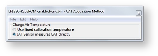
Charge Air Temp (CAT) also plays a critical part in the VE calculation. As a Charge Air Temp sensor is NOT fitted by the factory, we have to assume a fixed temperature and then make a calibrated compensation based against Intake Air Temp.
No Air Temp Sensor Fitted in the Charge Pipe
The Speed Density Temp Compensation map will adjust the SD VE calculation based on the current IAT, therefore attempting to calculate the true air density by calibration.
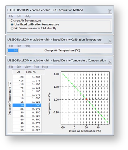
Intake Air temp sensor fitted in the charge pipe
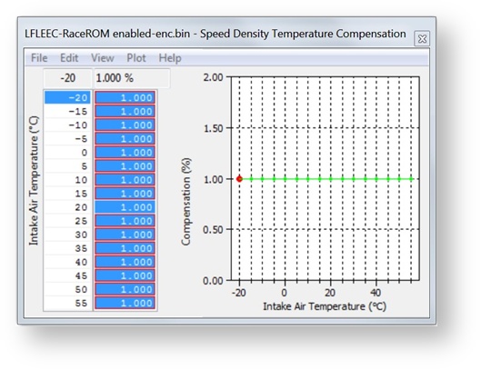
If the Air Intake Temp sensor (AIT) has been placed in the charge pipe and the IAT is measuring true CAT (after the turbo/supercharger and intercooler) then we do NOT need to use the ‘Speed Density Temp Compensation’ map (as VE calculation is including true CAT). In this situation, we need to select the CAT Acquisition Method of ‘IAT sensor measures the CAT directly’ option. We also need to set the values in the ‘Speed Density Temp Compensation’ to 100 as we are not ‘guessing’ the CAT anymore.
Hybrid SD mode options
Using Speed Density and MAF Sensor Together
The Speed Density feature can also be useful in applications where the MAF sensor is present, but the amount of airflow is higher than the MAF sensor can measure. In this scenario, the ECU can be programmed to use the MAF sensor at lower mass airflow values and switch to Speed Density for the higher values. You can specify threshold values of MAF, RPM and MAP that are required for Speed Density activation. The ECU will activate the Speed Density feature only when all three of these values are above their respective thresholds.
The threshold values are implemented using hysteresis. The 1st value should be higher than the 2nd value. The feature will activate when the parameter rises above the 1st value, and will deactivate when it falls below the 2nd value. You can also use the Speed Density feature in applications where the amount of airflow is lower than the MAF sensor can accurately measure. In this situation, enable the “Activate BELOW thresholds instead of ABOVE” checkbox. The ECU will activate the Speed Density feature when MAF, RPM and MAP are all below their respective thresholds. The default value for the thresholds is zero. If you use the “Activate BELOW thresholds instead of ABOVE” checkbox, then the feature will only be activated when all three parameters are below their respective thresholds. Therefore you need to set a high value into any thresholds that you are not using, otherwise the feature will not activate.
RaceROM implements a powerful Hybrid Speed Density mode which allows the Load Input to be switched between MAF and SD as required. This could be ‘MAF then SD’ or ‘SD then MAF’. The condition to switch between the two inputs can be one or several of the following:
- Engine Speed (RPM)
- MAP (Bar)
- Mass Airflow (g/sec)
If you wish to have the engine running on MAF at Idle and low load and then continue on MAF until 5000rpm then switch to SD past 5000rpm, set the RPM threshold like this.
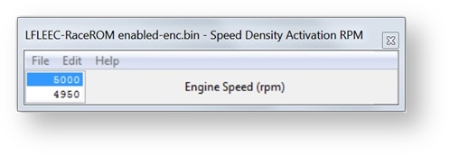
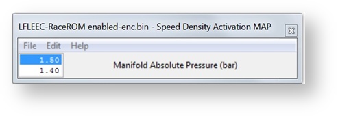
In addition you can specify that the boost pressure has to be over a certain pressure before the switch to SD as well (like over 5000rpm and over 1.5bar boost absolute or 7.5psi boost if you prefer), this is the Hybrid mode.
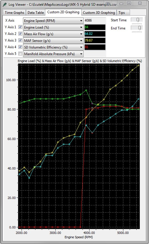
We need a smooth transition when swapping between ‘MAF and SD’ or ‘between SD and MAF’. For this to happen the MAF and SD have to read very similar airflows at the switch point. One major point to make is that ProECU can LOG the output of the MAF sensor (g/s) even if the MAF is not being used by the ECU (i.e. the ECU is running on SD not MAF). So to calibrate for a hybrid transition we need to Enable SD earlier than the switch point, if the switch point is to be 5500rpm then enable SD over 4000rpm. Even though the ECU is using SD past 4000rpm the MAF can still be logged, now we need to log the following three parameters.
- MAF Sensor (g/s) – The mass airflow reading from the MAF sensor
- Mass Air Flow (g/s)– The mass airflow used by the ECU in this case derived from the SD map
- SD Volumetric Efficiency (%) – The output of the SD map and we can see when SD starts working
As seen below the ECU is currently running on SD, we know this because the SD VE (RED line) starts working after 3800rpm and shows SD VE as 101% in the left hand screen shot. If the ECU was using MAF the SD VE reading would be 0%.
Good SD Translation
In this example the Mass Airflow readings for MAF and SD are very close between 3000 and 5000rpm so it would be a very smooth transition to swap from MAF to SD (or SD to MAF) at any RPM point shown below.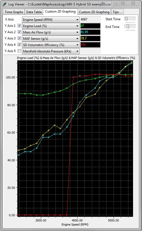
Bad SD Translation
In this example (Bad SD transition) you can see the SD map is poorly calibrated and the SD VE values are too low, so when the SD map is enabled at 3800rpm the Mass Airflow drops which will cause a Lean AFR and Advanced Ignition Timing, the engine may hesitate as the transition occurs.
Launch Control
The Launch Control feature limits maximum RPM during launch in an attempt to control wheel spin and allow the fastest possible take off.
Activate the launch control as follows
- Ensure the ‘Launch Control Enable’ checkbox is ON for the current Map Switch Mode
- Engine must be running and Vehicle must be stationary
- Press clutch pedal and move the gear stick to 1st position
- Quickly press the accelerator all the way to the floor
- Adjust launch RPM using the cruise control instruments
- Release the clutch to commence launch
When Launch Control is active, the rev limit will be set to the ‘Launch Control Rev Limit’. This limit defaults to the 'Launch Control Rev Limit Base" value and can be adjusted up and down using the cruise control instruments. Select "Res/Acc" to increase the launch RPM and "Set/Cst" to decrease it.
During the launch, the rev limit increases according to the 'Launch Control Rev Limit Delta, This 2D map, indexed by elapsed time, has multiple columns to allow you to set up a multistage system for best results.
Adjustments are provided that allow you to enrich the AFR and retard the timing when the vehicle is stationary in order to create pops and bangs. This adjustment is removed as soon as the vehicle starts to move.
The Launch Control feature is deactivated when one of the following conditions occurs:
- The vehicle speed exceeds the last column on the ‘Launch Control Rev Limit Delta Map’
- The driver lifts off the accelerator
- The driver performs a flatfoot shift
Integration with Map Switching
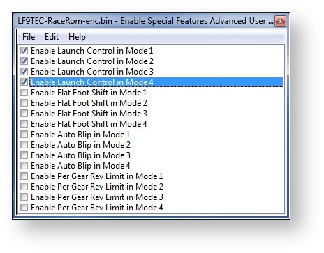
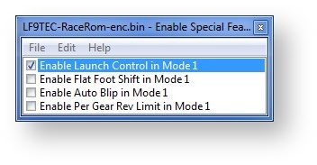
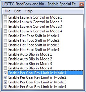
The Launch Control Feature can be enabled in any of the four calibration modes by selecting the appropriate checkboxes in the “Enable Special Features Advanced User Level” map. Retail Customers should use “Enable Special Features” map instead.
Flat Foot Shifting
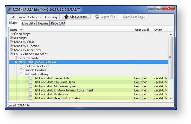
The Flat Foot Shifting feature allows the driver to up-shift without lifting his foot from the accelerator pedal. It is activated when all of the following conditions are met:
- ‘The Flat Foot Shift Enable’ checkbox is ON for the current Map Switch Mode
- The vehicle is travelling faster than the ‘Flat Foot Shift Minimum Speed’
- The accelerator amount is greater than the value in the ‘Full Accelerator Threshold Map’ The driver is pressing the Clutch pedal
At the moment when the Flat Foot Shifting feature activates, a temporary rev limit is set that is slightly higher than the current RPM. The ignition timing is retarded by a specified amount that reduces engine torque while preventing the RPM from rising too rapidly. When the driver completes the gear change, the temporary rev limit and timing adjustment are removed.
The Flat Foot Shifting Feature is cancelled when one of the following conditions occurs:
- The driver releases the Clutch pedal The driver lifts off the accelerator
- The vehicle speed falls below the value in the ‘Flat Foot Shift Minimum Speed Map’
Note: Flat Foot Shifting is not available on vehicles fitted with Automatic Transmissions.
An AFR adjustment is provided that allows you to enrich the AFR during the shift. The richer AFR cannot be measured from the exhaust gas due to the operation of the rev limiter.
Auto Blip
The Auto Blip feature applies a short burst of throttle when the driver is down-shifting under braking. This raises the RPM to keep the engine operating within its power band and provides a smooth entry into the lower gear by reducing engine braking.
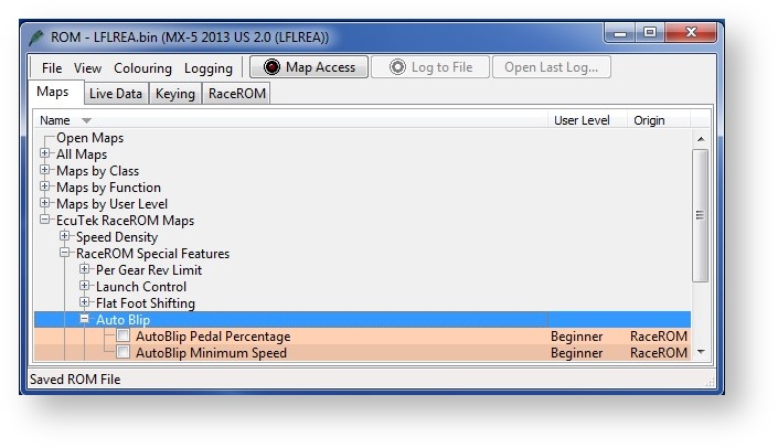
When the driver down-shifts while braking, the ECU will blip the accelerator. The amount of accelerator to apply is controlled by the ‘AutoBlip Pedal Percentage Map’ and is dependent on the engine RPM at the time of activation. The duration of the blip is controlled by the
‘AutoBlip Max Duration Map’.
The Auto Blip feature is activated when all of the following conditions are met:
- The ‘Auto Blip Enable checkbox’ is ON for the current Map Switch Mode
- The vehicle is travelling faster than the Auto Blip Minimum Speed
- The driver presses the clutch pedal while braking
- A minimum of 1 second has elapsed since the last auto blip
The accelerator blip is immediately cancelled when one of the following conditions occurs:
- The driver releases the Brake Pedal
- The driver releases the Clutch Pedal
- The driver presses the Accelerator Pedal
- The vehicle speed falls below the ‘Auto Blip Minimum Speed’
- The Auto Blip timer exceeds the value in the ‘Auto Blip Max Duration Map’
Note: Auto Blip is not available on vehicles fitted with Automatic Transmissions.
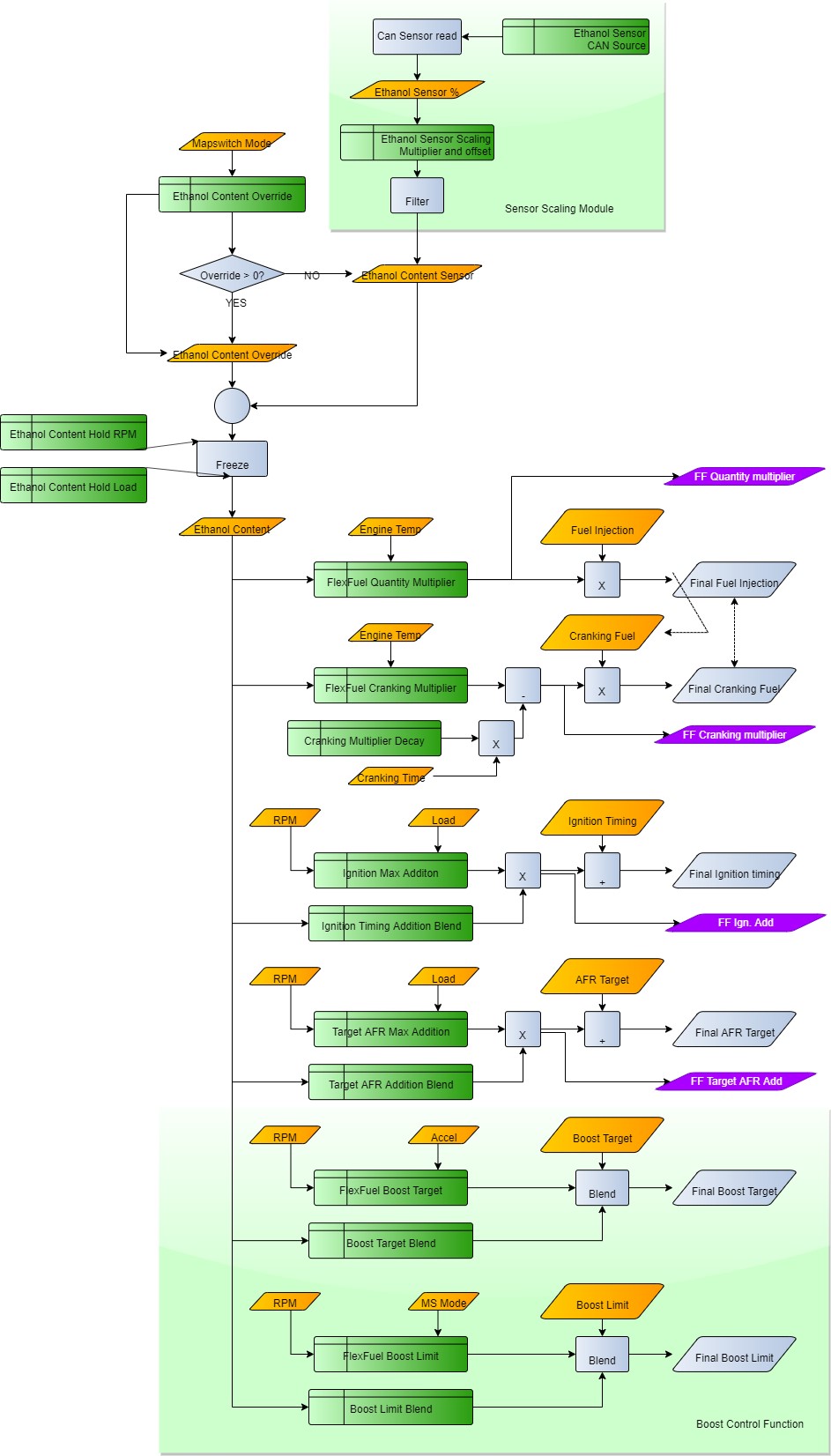
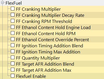
Flex Fuel
RaceROM for MX-5 now features our proven Flex Fuel system as utilised on GTR, BRZ, 370z and others. For a complete guide on how the system works check out our walk through here: RaceROM Flex Fuel
It uses a strategy of ignition and AFR target modifier maps for 100% E85 and 2d maps to determine how much of that modification is applied. The difference in base fuel requirement is taken care by the FlexFuel Quantity Multiplier map and a 2d blend map. Typically, 40% extra fuel will be required for 100% E85 to maintain the same Lambda (therefore the same reported petrol AFR), and the transition will be quite linear.
The change in ignition advance will probably more readily be applied with most, if not all the additional advance added by 50% E85. For 100% E85 there is a second boost target defined by Boost Target - Ethanol and a corresponding blend map to set how the boost target is determined from the two maps.
Currently the patch is supplied with typical values used in the FlexFuel Quantity Multiplier map so that any car with a FlexFuel sensor added should start and run reasonably well when E85 fuel is added. Remaining correction maps for ignition and AFR target are blank, the Boost Target and boost Limit - Ethanol map has default values identical to those found in the Target Boost map.
Notable differences between the two systems are as follows.
Table Map:
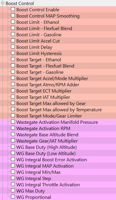
Additional tables allowing ethanol compensation for boost targets can be found in the Boost Control section of maps.
Closed Loop Boost Control 
We have introduced hard coded boost control using the CPC solenoid output from the ECU. This enables stable closed loop boost control without needing to make multiple custom maps. For a complete overview of the system check out our guide here: RaceROM Boost Control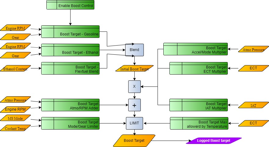
Table Map:
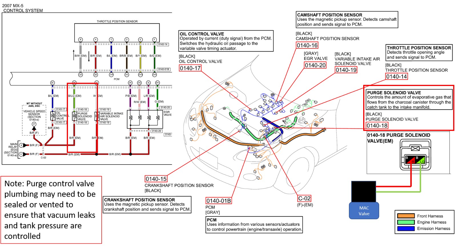
Boost Control Wiring
When using Boost control the OEM purge duty functionality is completely overwritten by the boost control strategy the wiring for the boost solenoid is something like below. The best option would be to use a CAN receiver with PWM output to translate the final WG duty and keep OEM hardware.
The factory CPC solenoid operates at 20hz, this is not adjustable due to ECU hardware limitations.
Per-Gear Rev Limits
The Per Gear Rev Limits feature allows you to define different rev limits for each gear. By setting a higher rev limit in lower gears you may be able to reduce the number of gearshifts required in attaining a given speed. E.g. 0-60mph (0-100km/h) tests. Separate sets of Per Gear Rev Limit maps are provided for each of the 4 modes. When Per Gear Rev Limits are not enabled, all modes will use the original ECU rev limit map.
This feature is only available on Manual Transmission vehicles.
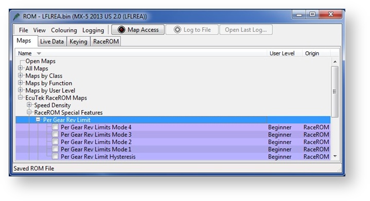
The Per Gear Rev Limits feature is enabled by the ‘Enable Per Gear Rev Limit’ checkboxes in the ‘Enable Special Features Advanced User. Level’ map or “Enable Special Features” for Retail Customers. When this feature is enabled, the ECU will use separate rev limits for each gear. The upper rev limit (fuel cut) is defined in the “Per Gear Rev Limits” map for each mode. The lower rev limit (fuel resume) is calculated by subtracting the value of “Per Gear Rev Limit Hysteresis” from the upper limit. For example, if the upper limit for the current gear is 7400 and the hysteresis is 100 then the lower limit will be 7300.
Improved Injector Scaling Multiplier
Simplifying injector scaling is a must for accurate and reliable fueling under all conditions. With the new Injector multiplier fitting larger injectors is now a simpler (more traditional method) of inputting the correct data into the size, latency and compensation maps.
Overrun Fuel Cut Disable
At popular demand, we've added the ability to disable the fuelcut during Overrun. It's a simple checkbox toggle that eitehr enables or disables the system allowing tuners to eliminate popping when fuel is cut on overrun.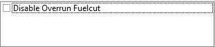
RaceROM Live Data
RaceROM provides additional diagnostics parameters to aid tuning and fault finding. Below is a list of the custom parameters:
- Accelerator Pedal – High resolution accelerator pedal position in %.
- Brake Pedal – An On / Off flag to display the state of the brake pedal.
- Clutch Pedal – An On / Off flag to display the state of the clutch pedal.
- Engine Load – High resolution engine load reading in g/rev. The same value used as the input to the fuel and ignition maps.
- Engine Speed – High resolution engine speed in RPM.
- Fuel Trim – Combined – An addition of Fuel Trim Long Term and Fuel Trim Short Term to display the total amount of fuel trim.
- Gear – The currently calculated gear from engine speed and vehicle speed.
- Intake Air Temperature – High resolution intake air temperature reading.
- Knock Sensor Input – The input value to the knock sensitivity map.
- MAF Sensor – The output from the mass air flow sensor before the speed density calculation. Will read zero if the MAF Sensor is unplugged.
- Manifold Absolute Pressure – The pressure in the manifold.
- Manifold Relative Pressure – The difference in pressure between atmospheric pressure and manifold pressure. This value is used as the input axis to the Injector Lag Time and Injector Flow Rate Compensation maps.
- Map Switch Mode – The currently selected map switch mode.
- Mass Air Flow – High resolution mass air flow reading. This is the value after the Speed Density calculation (if SD has been enabled) so may differ from the MAF Sensor value if SD is active.
- SD On / Off – An On / Off flag to display the operating state of the Speed Density system.Will only be enabled if all the conditions for Speed Density are met.
- SD Volumetric Efficiency – The output from the Speed Density Volumetric Efficiency map, before the intake air temperature and throttle delta compensations.
- SD Volumetric Efficiency – Calc – The approximate Speed Density Volumetric Efficiency. This value is calculated from Engine Speed, Intake Air Temperature, Manifold Pressure and Mass Air Flow.
- Throttle Delta – The rate of change of the throttle pedal in a specific time period.
- Wheel Speed – Front Left – The wheel speed of the front left wheel.
- Wheel Speed – Front Right – The wheel speed of the front right wheel.
- Wheel Speed – Rear Left – The wheel speed of the rear left wheel.
- Wheel Speed – Rear Right – The wheel speed of the rear right wheel.
EcuTek ProECU tuning tools tools should only be used by experienced tuners who understand the product and engine calibration.
If you do not fully understand this product then you WILL damage your engine, ECU or your vehicle.
Please ensure you fully read all EcuTek manuals BEFORE attempting to use ProECU with your laptop or your vehicle.
Use with extreme caution and understanding at all times, if in doubt then do not proceed.
EcuTek accepts no responsibility for any damage to the engine, ECU or any part of the vehicle that results directly or indirectly from using the product.
** If you are in any doubt that you do NOT have the experience required to use this product then you should NOT USE IT **
Retail customers
** If you have any doubt that you do NOT have the experience required to use this product then you should NOT USE IT, you should simply contact your EcuTek Master Tuner shown clearly on the top of your Programming Kit or visit your preferred tuning shop to have a professional tuner use it for you **