Lancer Evo 5-9 Tuning Guide
- Brandyn Mowat
Lancer Evo 5-9 ProECU Tuning Guide
Summary of Software
Data logging can be made on EVO7-8 models using laptop based generic OBD2 diagnostic software; this can provide Engine RPM, Engine Load% and Ignition Timing. EVO 5-6 models do not support OBD2 diagnostics. If you have a Subaru
Select Monitor (Hitachi HDM2000 diagnostic monitor) there is a Mitsubishi Diagnostic Cartridge available (that will plug into the Select Monitor Cartridge port) direct from Japan at http://www.himic.co.jp/test/shouhin/hdm/table.htm (Latest Cartridge version is V1.46)
this is NOT something EcuTeK can source or supply.
EcuTeK cannot support Mitsubishi EVO ECUs with DeltaDash Data logging software due to the EVO using the much slower OBD2 communication protocol. We use Laptop based generic OBD software called ScanMasterPro from http://www.onboarddiagnostics.co.uk/eobd/scanmasterpro.html
ProECU software has been introduced to allow reprogramming of the factory ECU in order to tune the necessary components of the calibration in order to allow for modifications and increases in power. This is not a standalone repalcement ECU so you shouldn't run into the associated issues or disadvantages of setting up a purpose-built ECU and control system from scratch.
The software allows easy control over most factory parameters including:
- Boost Targets and wastegate control
- Target AFR
- Ignition Timing
- Fuel Delivery including fuel pump calibration (using the same style pump as OEM)
- Airflow Measurement and fuel compensation
Supplemental Content
Platform Specific
General
Table of Contents
Boost Control
Boost Limit
This determines the boost limit against Engine Load. The Engine load is similar to Boost Pressure so 100% Engine Load equals roughly 0 psi (or atmospheric pressure). An engine load of 200% is approximately 1 Bar Boost (2 Bar Absolute). You MUST add the 1D Map value of ‘Boost Control - Desired Engine Load Offset’ to see the true boost limit threshold.
Turbo Dynamics
The Turbo Dynamics tables are used for ‘boost’ error compensation. These maps control the rate at which the wastegate duty cycle is altered (according to amount of error) in order to produce the desired level of boost. This map represents the actual change in duty cycle according to the amount of error.
Standard dynamics are set to take a large percentage of wastegate duty with only a small amount of boost error causing boost to drop very quickly. If you struggle with overboost and boost oscillations then we suggest you reduce the big values in the map. This will stop the boost pressure from ‘surging’ either side of the target value.
Wastegate Duty
The Maximum allowed wastegate solenoid duty at each RPM point, sometimes this is less around peak torque (3-4000rpm) to prevent over boost. The number of wastegate duty maps varies between different ROM files though there are usually 3 or 4 maps.
We suggest all maps are set the same as the ECU can swap between these in different conditions, which will affect boost control.
Boost Desired Engine Load
Boost control is managed by ‘Boost Desired Engine Load’ maps. Values in the table MUST be added to the ‘Boost Control - Desired Engine Load Offset’ (found under ‘Data values’) to see the true Desired Engine Load target. There are normally 3 or 4 of these maps. These tables are used differently between regions and models. It is best to set all the tables the same.
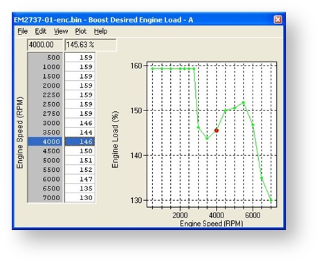
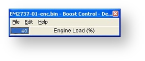
We can see below the ‘Desired Engine Load’ at 4000rpm is 146% (Engine Load can be seen in either the Fuel Table or Ignition Table). We can also see the Desired Engine Load Offset is 40%, so the total Desired Engine load at 4000 rpm would be 196%. This is equivalent to about 1.96 Bar Boost
(absolute), these are Engine Load and NOT PSI or Bar, though approximately 100% Engine Load equals Atmospheric Pressure, which is 0 psi, 0 Bar of boost. 200% equals around 14-15psi, 1 Bar boost. Engine Load of 100% roughly corresponds to an absolute manifold pressure of 1 bar, so 225% would be 2.25 Bar i.e. 1.25 Bar of boost
It is possible with a bit of time you may find that the ECU uses these for different desired boost in different gears or in Open/Closed Loop fuelling mode and it may even default to one of these in the event of a CEL condition.
Boost Control - Desired Engine Load OFFSET
The Desired Engine Load OFFSET value MUST be added to all the 2D Map “Boost Desired Engine Load” maps to see the correct Desired Engine Load for reference against the Fuel or Ignition tables. Increasing this value will raise all of the Boost curves together by the same amount.
Boost Limit Timer Delay
If the Engine Load exceeds the 2D Map ‘Boost Limit’ this timer must expire before the Boost cut will occur. The standard time is normally 1000milliseconds (1 second) and the maximum setting is 6375 milliseconds (just over 6 seconds). So in the standard ROM you can exceed the standard ‘Boost Limit’ 2D Map for 1 second before Boost/Fuel cut will occur. This explains quite often after a full performance exhaust system has been fitted that the vehicle will Boost/Fuel cut in 5th and 6th gear around 3000 rpm as this is when maximum boost is created. If the boost does not reduce below the Boost Limit within 1 second then Fuel Cut will cut the Injectors for a split second causing complete power loss on peak torque.
Wastegate Solenoid (Activation-Deactivation)
The ON and OFF engine RPM that the wastegate solenoid is active. If the vehicle Rev Limit is raised to 8000rpm then it would be necessary to raise the wastegate solenoid switch off RPM from 7500 rpm to say 7800 rpm. There is a low RPM limit to stop the solenoid working at low engine RPM which would be to noisy and unnecessary.
The parameters work as follows:
- Wastegate Solenoid Activation RPM – Active
- Low RPM solenoid ‘turn on’. This will be a higher value than above
- Low RPM solenoid ‘turn on’. This will be a higher value than above
- Wastegate Solenoid Activation RPM – De-Activate
- Low RPM solenoid ‘turn off’. This will be a lower value than above
- Low RPM solenoid ‘turn off’. This will be a lower value than above
- Wastegate Solenoid De-Activation RPM – De-Activate
- High RPM solenoid ‘turn off’. This will be a higher value than above
- High RPM solenoid ‘turn off’. This will be a higher value than above
- Wastegate Solenoid De-Activation RPM – De-Activate
- High RPM solenoid turn on. This will be a lower value than above
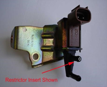
If Desired Engine Load and Wastegate Tables are set to maximum and the desired boost is not achieved then you may need to change the Wastegate Solenoid restrictors. The boost increase is dependent upon the size of the exhaust system. If you want 1.4 bar and only make 1.3 bar then there is a small restrictor you can remove pressed into the Wastegate Solenoid “IN” port. On Evo 5-6 it is a very small black plastic insert and Evo 7-8 it is a small steel insert (on some EVO 8 and 9, this restrictor has been made of plastic.) also, on USA spec Evo 8 there is a restrictor in the line leading from the boost control solenoid to the ‘T’ junction at the turbocharger. Removing the restrictor with a small self tapping screw will allow the wastegate solenoid to “vent” more boost pressure from the actuator giving a boost increase of about 1-2 psi. If this still does not increase the boost pressure to the desired level then you will need to make the other restrictor fitted in the wastegate solenoid supply pipe smaller. This restrictor is located down by the turbocharger compressor housing. It is located inside the small vacuum tube in-between the “T” piece (that goes to the wastegate actuator) and the Compressor housing pressed fitting that supplies the positive boost pressure for the wastegate solenoid. It is normally around 1.1mm I.D. (varies between models) and can by heated with Butane Gas torch and filled with solder. Then just redrill the restrictor to the new required size (normally 1.0mm or 0.95mm).
You will likely have to change the ‘Max Wastegate Duty’ maps to prevent ‘overboost’
Generally about 360-370 BHP is the maximum for the standard turbochargers, later Evo7 and Evo8 models seem to make more power than Evo 5 and Evo 6 versions.
We advise to limit positive manifold pressure to 1.6 bar with the standard turbo
Camshaft Timing
VVT (Variable Valve Timing) Map (MIVEC)
This map controls the advance of the intake cam (note that 1 degree at the camshaft is 2 degrees at the crankshaft). This number is in camshaft degrees before Top Dead Centre. Modifying the cam timing map can increase power and turbo response, but too much advance can significantly increase in cylinder pressures. This is dependent on Camshafts, Turbocharger and naturally any item which will change.
Fuelling
Fuel Maps
The fuel maps contain AFR data, based on RPM and calculated engine load. When altering fuel maps, bear in mind that the AFRs are only theoretical, they are calculated AFR, and that the ECU will operate in open loop fuelling mode when on full power.
For this reason, add and remove fuel in small increments, and watch for changes in actual AFR, based on wideband lambda readings. ALL tuning should be checked with a wideband Lambda sensor.
The A/F Ratio is only under closed loop control on part throttle.
Generally once the vehicle makes positive boost pressure the AFR is in open loop and reading from the Calculated Fuel Table. Changing something simple like Fuel pressure from say 3.0Bar to 4.0Bar would make this table inaccurate, bear this in mind.
High Octane
This fuel map is used when there is no detonation detected. If the ECU has been tuned properly, this is the only fuel map that will be accessed.
Low Octane
If continuous detonation occurs or a serious CEL occurs the ECU will default to this map. Make sure that the values in this map are ‘richer’ in positive pressure than the ‘high octane’ map.
Open Loop Load
This map determines when the ECU switches from ‘Closed Loop Lambda Control’ to ‘Open Loop’ based on ‘Engine Load’. When the Engine Load value is reached (at X RPM) the ECU will switch to ‘Open Loop’ fuelling.
Injector Battery Voltage Compensation
This table needs to be altered when the original Fuel Injectors have been replaced by an aftermarket brand. This is the delay time added to compensate for the ‘turn on (reaction)’ time of a fuel injector. This ‘lag time’ changes with battery voltage, the higher the voltage the quicker the injector is able to switch. Most injector manufactures offer ‘injector lag time’ sheets for their injectors.
Acceleration Enrichment
This map determines the percentage of fuel added at each Rpm based off of throttle pedal input.
Injector Scaling
Injector Scale size in CC, if the injectors have been replaced then change this calibration value. You may also need to alter the 2D Map ‘Injector Battery Voltage Compensation Map’.
This map is not always a direct correlation to actual fuel injector size.
Minimum Coolant Temperature for Closed Loop
This is the coolant temperature (degrees Celsius) that ‘closed loop’ fuelling is activated.
Lean Spool: Enable RPM
Before this RPM, the ECU will run AFRs close to 14:1. Can be helpful for ‘spooling’ larger turbochargers, but be mindful of higher EGTs and possible detonation.
AFR should always be checked with a wideband Lambda sensor and we would suggest a target AFR of around 11.5:1 at peak torque (3500-4000rpm) dropping to around 11:1 by 6000rpm
The standard Injectors are generally OK for around 380 BHP using a high flow fuel pump; don’t forget fuel pressure can also be raised to increase AFR.
Idle
High Intake Air Temp Idle
When Intake air temperature is too high the idle speed is increased to make the idle more stable, this is different for both A/C activated and deactivated.
The amount the idle speed actually increases will depend on the amount of Idle Stepper Motor ‘steps’ the ECU is allowed to use to increase the Idle Speed.
The requested ‘idle speed’ and ‘step’ parameter will need to be modified together to achieve positive results.
Ignition
Ignition Maps
These maps contain the ignition timing values, based on RPM and calculated engine load. Detonation should always be listened for, the ECU will remove Ignition timing if detonation occurs but it is safer to avoid detonation as the ECU takes crude action to deal with det.
The High and Low Octane maps operate under the same circumstances as the fuel maps.
Evo 5-6 tend to use NGK PGR6A these should always be replaced with the EVO7 PGR7A models or use the superior Iridium IGR7A-G. Other Spark Plugs are available including BPR7EIX (you can also search the Internet to find others). EVO 9 has different “longer reach” special spark plugs.
Detonation should be checked for using an Engine Knock listening device or a stethoscope, the High Octane Ignition map should be adjusted if detonation is heard at the correct Engine RPM and Engine Load (OBD2 software).
Limiters
Rev Limit
Hard cut rev limit
Speed Limiter (on-off)
Vehicle Speed Limiter, Japanese Domestic models are normally limited to 180 KPH / 118 MPH.
Stationary Rev Limit – Launch Control
Secondary RPM limiter that is engaged when the vehicle is stationary, very useful for ‘launch control’
Misc.
IC Relay (Intercooler water spray control)
Various parameters for activation and control of the intercooler water spray system.
- IC Relay Timer ON Mode Switch Time
- Time period for activation of intercooler water spray system from ‘switch on (auto)’
- Time period for activation of intercooler water spray system from ‘switch on (auto)’
- IC Relay Timer Control RPM
- Minimum RPM for system activation (in Auto mode)
- Minimum RPM for system activation (in Auto mode)
- IC Relay Control Vehicle Speed
- Minimum Vehicle Speed for system activation (in Auto mode).
- Minimum Vehicle Speed for system activation (in Auto mode).
- IC Relay Control EV
- Minimum Engine Load for system activation (in Auto mode).
- Minimum Engine Load for system activation (in Auto mode).
- IC Relay Timer On Time
- Amount of time that water will spray when all control parameters are met (RPM, Speed, Load and Temperature).
- Amount of time that water will spray when all control parameters are met (RPM, Speed, Load and Temperature).
- IC Relay Timer Off Time
- Minimum amount of time between water spray events.
- Minimum amount of time between water spray events.
- IC Relay Air Temp
- Temperature (in Celsius) above which the water spray system is active.
- Temperature (in Celsius) above which the water spray system is active.
EcuTek ProECU tuning tools tools should only be used by experienced tuners who understand the product and engine calibration.
If you do not fully understand this product then you WILL damage your engine, ECU or your vehicle.
Please ensure you fully read all EcuTek manuals BEFORE attempting to use ProECU with your laptop or your vehicle.
Use with extreme caution and understanding at all times, if in doubt then do not proceed.
EcuTek accepts no responsibility for any damage to the engine, ECU or any part of the vehicle that results directly or indirectly from using the product.
** If you are in any doubt that you do NOT have the experience required to use this product then you should NOT USE IT **
Retail customers
** If you have any doubt that you do NOT have the experience required to use this product then you should NOT USE IT, you should simply contact your EcuTek Master Tuner shown clearly on the top of your Programming Kit or visit your preferred tuning shop to have a professional tuner use it for you **