Mitsubishi Diesel General Information
- Brandyn Mowat
Common Rail
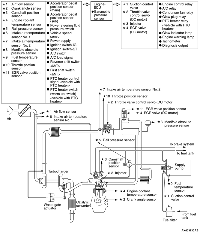
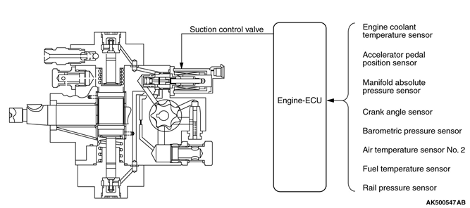
The common rail engine control system is adopted for the fuel injection system. The common rail engine control system consists of sensors that detect the conditions of the engine and the actuators that operate under the control of the engine-ECU, which calculates and determines the engine control contents based on the signals provided by the sensors. The engine-ECU effects the fuel injection control, boost pressure control and exhaust gas recirculation (EGR) control. In addition, the engine-ECU contains a self-diagnosis system to facilitate the diagnosis of malfunctions in the major sensors and actuators.
Mitsubishi use the DENSO Common Rail System:
The DENSO common rail system employs five injections. That is five distinct injections during each combustion stroke, each with a predetermined and metered fuel quantity.
The multiple injections are designated as the pilot, pre, main, after and post injections.
The Pilot injection, occurring well before ignition, provides tim e for fuel and air to m ix. The “pre” injection, shortens the ignition delay during the m ain injection and, as a result, reduces the generation of nitrogen oxide, noise and engine vibration.
The Main injection is, well, the m in injection, providing the fuel for combustion and power.
The After injection occurs a split -second after the main injection and re-burns any remaining PM.
The Post injection helps manage the temperature of the exhaust gases, which makes the exhaust processing in the engine’s after-treatment cycle more effective.
System Block Diagram
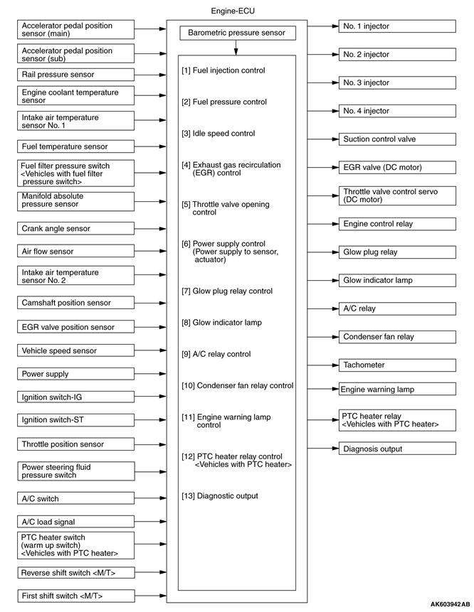
In the common rail type fuel injection system, the pressurized fuel is supplied by the supply pump, stored in the common rail, and injected through the solenoid type injectors.
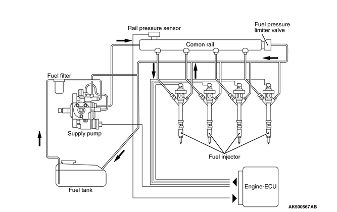
The engine-ECU transmits signals to the solenoid valves in the injectors in order to control the fuel injection timing and injection amount.In the common rail type fuel injection system, the pressurized fuel (approximately 180 MPa max.) supplied by the supply pump is stored in the common rail. Thus, the system ensures a stable injection pressure at all times, even at low speeds, without being affected by engine speed or load. The engine-ECU monitors the internal pressure of the common rail by way of the rail pressure sensor, and actuates the suction control valve to deliver fuel, thus enabling the fuel in the common rail to attain the target pressure. Furthermore, the system uses a limiter valve in the common rail to prevent the fuel pressure in the common rail from rising excessively. The engine-ECU sends signals to the solenoid type injectors, which use solenoid valves to open and close the fuel passages. Because these solenoid type injectors can precisely control the fuel injection amount and injection timing, they can suppress the generation of black smoke, which is unique to diesel engines.Furthermore, the system divides the injection of fuel in two stages, consisting of pilot injection followed by main injection. This allows the combustion to start gently during main injection, effectively reducing vibration and noise.
Supply Pump
The supply pump draws fuel from the fuel tank, pressurizes it (to approximately 180 MPa max.), and delivers it to the common rail.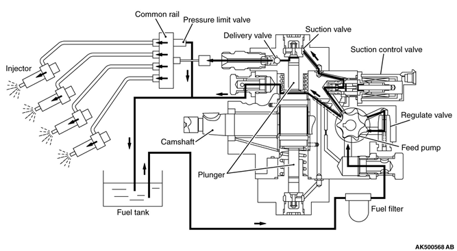
- Feed pump: Draws fuel from the fuel tank, into the supply pump.
- Regulator valve: Returns the fuel to the fuel tank when the fuel pressure between the feed pump and the suction control valve becomes higher than a predetermined value.
- Suction control valve: Regulates the amount of fuel that is delivered to the common rail. ·Plunger: Moves constantly at full stroke in order to pressurize the fuel in the high-pressure chamber.
- Delivery valve: Stops the fuel back flow from the delivery side when the fuel is suctioned into the high-pressure chamber.
- Suction valve: Prevents the fuel, which is pressurized in the high-pressure chamber, from flowing back.
Construction description
The supply pump camshaft rotation in correspondence with the crankshaft is converted into the two movements: One is the operation of the feed pump, which draws fuel from the fuel tank up into the supply pump, and another one is the reciprocal movements of two opposing plungers alternately by the cam on the shaft.
The electronically controlled suction control valve, which is located between the feed pump and the high-pressure chamber, regulates the amount of fuel that is supplied to the high-pressure chamber in accordance with the signals received from the engine-ECU.
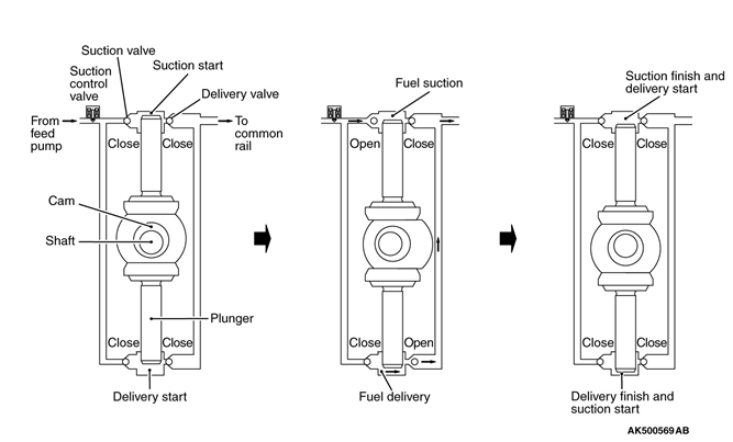
The two plungers move reciprocally to alternate the following functions: draws fuel past the suction control valve into the high-pressure chamber, and pressurizes the fuel and supplies it to the common rail. In other words, when one high-pressure chamber is performing a fuel suction stroke, the other is performing a fuel compression stroke. These movements enable the supply pump to perform two fuel pumping motions while the injectors injection fuel twice during each revolution of the engine, thus maintaining a constant fuel pressure in the common rail. Furthermore, the system enhances accuracy by using the signals, which are output by the rail pressure sensor located in the common rail, for feedback control.
Pump Learning
The engine-ECU checks the relationship between the amperage of the linear solenoid of the suction control valve and the pump delivery amount. Then, the engine-ECU corrects the pump delivery amount in relation to the amperage, based on the map values of the fuel pressure and amperage.
If the supply pump is replaced, it is necessary to use the M.U.T.-III tester to delete the previously learned value and acquire a new value. This learning process is performed for several seconds after the engine has been warmed up, and in a completely no-load state.
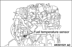
Fuel Temperature Sensor
The fuel temperature sensor which is mounted on the supply pump detects the temperature of the fuel through the changes through a thermistor style sensor.
Typically as fuel temperature goes up the output voltage goes down.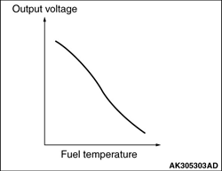
Suction Control Valve
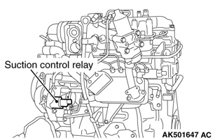
The suction control valve, which is a linear solenoid valve that operates under the duty-cycle rate, is mounted on the supply pump. In order to control the amount of fuel that flows from the feed pump to the high-pressure chamber, it reads actuation signals that are output by the engine-ECU. When the ON duty cycle ratio is lower, the valve opening increases. Then the amount of the fuel flowing into the common rail increases as well as the fuel pressure in the common rail. When the ON duty cycle ratio is higher, the valve opening decreases. Then the amount of the fuel flowing into the common rail decreases as well as the fuel pressure in the common rail.
Components and their Functions
| Type | Name | Function |
|---|---|---|
ECU | Engine-ECU | Effects control to actuate the actuators in accordance with the driving conditions, based on the signals input by the sensors. |
Sensors | Ignition switch-IG | Detects the ignition switch-IG ON/OFF signals. The engineECU turns the engine control relay ON/OFF in accordance with these signals. |
Ignition switch-ST | Detects that the engine is cranking. Based on this signal, the engine-ECU effects fuel injection amount and fuel injection | |
timing control that are suited for starting the engine. | ||
Accelerator pedal position sensors (main and sub) | Detects the position of the accelerator pedal and input it into the engine-ECU. Based on the voltage output by these sensors, the engine-ECU controls fuel injection amount in accordance with the accelerator pedal position. | |
Rail pressure sensor | Detects the fuel pressure in the common rail and input it into the engine-ECU. The engine-ECU uses the voltage that is output by this sensor to regulate the fuel pressure in the common rail. | |
Engine coolant temperature sensor | Contains a thermistor to detect the engine coolant temperature. The engine-ECU determines the warm-up condition of the engine based on the signals output by this sensor, and controls the pre-glow time and fuel injection amount. | |
Intake air temperature sensor No. 2 | Contains a thermistor to detect the boost air temperature. Based on the voltage that is output by this sensor, the engineECU corrects the amount of the exhaust gas recirculate rate. | |
Fuel temperature sensor | Contains a thermistor to detect the fuel temperature. Based on the voltage that is output by this sensor, the engine-ECU corrects the fuel injection amount to suit the fuel temperature. | |
Crank angle sensor | Detects the engine speed and crankshaft position. Based on this signal, the engine-ECU controls the fuel injection amount and fuel injection timing. | |
Air flow sensor | Measures the current air mass. The engine-ECU calculates the exhaust gas recirculation rate based on this output signal. | |
Intake air temperature sensor No. 1 | Contains a thermistor to detect the intake air temperature. Based on the voltage that is output by this sensor, the ECU corrects the amount of the exhaust gas recirculation rate. | |
| Throttle position sensor | Detects the position of the throttle valve and converts it into the output voltage. Based on the voltage output by this sensor, the engine-ECU effects feedback control for the throttle valve position. | |
Camshaft position sensor | Detects the No. 1 cylinder compression top dead center position by means of a magnetic resistance element. | |
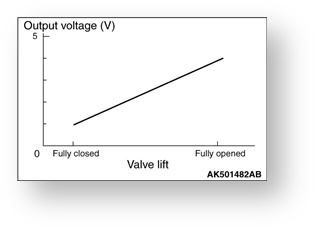
| EGR valve position Sensor | Detects the position of the EGR valve and converts it into the sensor output voltage. Based on the voltage output by this sensor, the engine-ECU effects feedback control for the EGR valve position. | |
Manifold absolute pressure sensor | Detects the absolute pressure in the inlet manifold. The engine-ECU uses the voltage that is output by this sensor to control the fuel injection amount. | |
Vehicle speed sensor | Detects the vehicle speed and converts it into the signal voltage. Based on the signal voltage output by this sensor, the engine-ECU controls the fuel injection amount. | |
Barometric pressure sensor | Detects the barometric pressure. The engine-ECU corrects the fuel injection amount and fuel injection timing to suit the barometric pressure. | |
A/C switch | Detects the ON/OFF condition of the air conditioner and inputs it to the engine-ECU. | |
A/C load signal | Air conditioner inputs the drive state of the compressor to the engine-ECU. The engine-ECU controls to air conditioner idleup engine speed using this signal. | |
Power steering fluid pressure switch | Detects the ON/OFF condition of the power steering load and inputs it to the engine-ECU. | |
First shift switch | Detects the first shift of the transmission. The engine-ECU confines the engine speed at the start by using this switch signal. | |
Reverse shift switch | Detects the reverse shift of the transmission. The engine-ECU confines the engine speed by using this switch signal. | |
Fuel filter pressure switch <Vehicles with fuel filter pressure switch> | A switch using contact switch for monitoring fuel pressure state between fuel filter and supply pump and for converting finding into voltage signal, which is output to engine-ECU. This allows engine-ECU to detect clogged fuel filter. | |
PTC heater switch (warm up switch) <Vehicles with PTC heater> | A switch using contact switch for detecting on/off state of PTC heater switch and for converting finding into voltage signal, which is output to engine-ECU. Engine-ECU controls PTC heater, based on this signal. | |
Actuators | Injectors | Inject fuel in accordance with the actuation signals provided by the engine-ECU. |
Suction control valve | Adjusts the fuel flow into the common rail in accordance with the signals provided by the engine-ECU. This allows controlling the fuel pressure in the common rail. | |
Engine control relay | In accordance with the signals provided by the engine-ECU, this relay controls the power supply for the engine-ECU, sensors and actuators. | |
Throttle valve control servo | Controls the actuator of the throttle valve in accordance with the signals provided by the engine-ECU. | |
EGR valve (stepper motor) | Controls the EGR flow rate in accordance with the signals received from the engine-ECU. | |
Glow indicator lamp | Informs the driver with illuminating lamp during the preparedness in the engine start. | |
Glow plug relay | Controls the actuation of the glow plugs in accordance with the signals provided by the engine-ECU. | |
Condenser fan relay | Controls the actuation of the condenser fan in accordance with the signals provided by the engine-ECU. | |
A/C relay | Controls the actuation of the A/C compressor in accordance with the signals provided by the engine-ECU. | |
Engine warning lamp | Informs the driver with illuminating lamp when the malfunction of the engine is detected by using various sensors. | |
PTC heater relay (warm up switch) <Vehicles with PTC heater> | A relay using signal from engine-ECU for turning on/off electrical supply switch for PTC heater. |
ECU
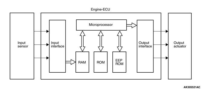
In accordance with the data input by the sensors, the engine-ECU determines (calculates) optimal control and actuates the output actuators to suit the constantly changing driving conditions. The engine-ECU consists of a 32-bit microprocessor, random access memory (RAM), read only memory (ROM), and input-output (I/O interface).
It has adopted a rewritable flash-memory ROM in which the control data can be changed or corrected through the use of a special tool. In addition, it has adopted an electrically erasable programmable read only memory (EEP ROM) so that the learned correction data will not be deleted even if the battery is disconnected.
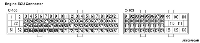
ECU Connector Input / Output Pin Arrangement
| ECU Pin | Function |
|---|---|
1 | No. 1, 4 injector battery |
2 | No. 2, 3 injector battery |
3 | No. 3 injector |
4 | No. 3 injector |
5 | No. 2 injector |
6 | No. 2 injector |
11 | Engine check lamp |
13 | A/C load signal |
14 | PTC heater switch (warm up switch) <vehicle with PTC heater> |
15 | A/C switch |
17 | Suction control valve (positive) |
19 | EGR motor (positive) |
20 | EGR motor (negative) |
22 | Ground |
23 | No. 1 injector |
24 | No. 1 injector |
25 | No. 4 injector |
26 | No. 4 injector |
28 | Glow lamp |
29 | Glow plug relay |
35 | PTC heater control signal <vehicles with PTC heater> |
37 | Suction control valve (negative) |
38 | PTC heater relay 2 <vehicles with PTC Heater |
39 | Condenser fan relay |
40 | A/C relay |
41 | PTC heater relay 1 <vehicles with PTC heater> |
49 | Intake air temperature sensor 1 |
50 | Air flow sensor |
51 | EGR position sensor |
52 | Manifold absolute pressure sensor |
53 | Engine coolant temperature sensor |
54 | Fuel temperature sensor |
55 | Rail pressure sensor backup |
56 | Rail pressure sensor |
57 | Camshaft position sensor |
58 | Crank angle sensor |
59 | Camshaft position sensor power supply |
60 | Crank angle sensor power supply |
61 | Ground |
65 | Intake air temperature sensor 2 |
70 | Intake air temperature sensor 1 ground |
71 | Air flow sensor ground |
72 | EGR position sensor ground |
73 | Manifold absolute pressure sensor ground |
74 | Engine coolant temperature sensor ground |
75 | Sensor ground |
76 | Rail pressure sensor ground |
78 | Camshaft position sensor ground |
79 | Crank angle sensor ground |
80 | Sensor source |
81 | Rail pressure sensor power supply |
91 | Tachometer |
92 | Ignition switch - IG |
96 | Power steering switch |
99 | Battery |
100 | Battery |
101 | Battery (backup with monitor) |
102 | Fuel filter pressure switch <vehicles with fuel filter pressure switch> |
103 | Ignition switch - ST |
104 | First shift switch |
105 | Reverse shift switch |
109 | Engine control relay |
111 | Throttle valve control servo (-) |
112 | Accelerator pedal position sensor (sub) power supply |
113 | Accelerator pedal position sensor (sub) |
114 | Accelerator pedal position sensor (sub) ground |
117 | CAN interface (high) |
119 | Vehicle speed sensor |
120 | Accelerator pedal position sensor (main) power supply |
121 | Accelerator pedal position sensor (main) |
122 | Accelerator pedal position sensor (main) ground |
124 | Throttle position sensor |
125 | CAN interface (low) |
128 | Ground |
130 | Throttle valve control servo (+) |
Fuel Injection Control
Fuel Injection Amount Control
Based on the signals provided by various sensors, the engine-ECU calculates the optimal fuel injection amount that suits the operating conditions. Then, it controls the fuel injection amount by actuating the solenoid valves of the injectors located at the cylinders.
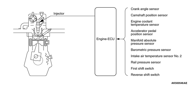
The engine-ECU compares the basic fuel injection amount against the maximum fuel injection amount. Then, it uses the lower injection amount to calculate the intended injection amount, which is achieved by controlling the actuation time of the solenoid valves in the injectors. The longer the actuation time of the solenoid valves, the greater will be the injection amount. Conversely, the shorter the actuation time of the solenoid valves, the lesser will be the injection amount.
Basic fuel injection amount:
Calculated based on the signals provided by the accelerator pedal position sensor and the crank angle sensor.
Maximum fuel injection amount:
Calculated by applying corrections based on various sensors to the basic fuel injection amount.
Drive Train System Protection Control
This control protects the drive train from extreme loads at the start by controlling the engine speed under the predetermined speed of 3,000 r/min. The engine-ECU controls the fuel injection amount at the following the conditions.
- The transmission shift: first or reverse
- The vehicle speed: 5 km/h or lower
Learning Pre-Injection Amount
The engine-ECU determines the variances in the fuel injection amount by monitoring the engine speed. Based on the changes in engine speed, the engine-ECU regulates the actual injection amount for each cylinder by correcting their fuel injection amount command values. The engineECU stores the correction values in its memory in the form of learning values. The engine-ECU keeps the learning values stored in its memory until it is updated with subsequent learning values. The system learns the injection amount with a higher injection pressure than normal. Although the sound of the engine changes while the system is learning the injection amount, this is normal. The system learns the injection amount automatically, or can be forced to learn through the use of an M.U.T.-III.
Fuel Injection Timing Control
Based on the signals provided by various sensors, the engine-ECU calculates the optimal fuel injection timing that suits the operating conditions. Then, it controls the fuel injection timing by actuating the injectors. In addition, the engine-ECU performs pilot injection, which injects fuel preceding the main injection, for the purpose of reducing the generation of combustion sound and NOx emissions. Based on the signals input by various sensors, the engine-ECU calculates the fuel injection timing by applying corrections to a predetermined basic target fuel injection timing. Thus, it controls the injection timing by controlling the actuation timing of the injectors.
Basic Target Fuel Injection Timing
Calculated based on the crank angle sensor signal and the fuel injection amount. The system advances the actuation timing of the injectors to advance the injection timing, and retards the actuation timing of the injectors to retard the injection timing.The ignition becomes retarded only during the main injection, thus increasing the amount of fuel that is injected from the start of injection until the fuel is ignited. For this reason, the combustion of the fuel occurs suddenly at a high temperature and pressure. This increases the combustion sound and the amount of NOx that is emitted. With the combination of pilot injection and main injection, the pilot injection that injects a small amount of fuel preceding the main injection makes the combustion constant, thus reducing the combustion sound and the amount of NOx that is emitted.
Fuel Pressure Control
Based on the signals provided by various sensors, the engine-ECU calculates the optimal fuel injection pressure that suits the operating conditions. Then, it actuates the suction control valve to control the fuel injection pressure.
Based on the signal input by the crank angle sensor and the fuel injection amount, the engineECU calculates the fuel injection pressure. Then, it actuates the suction control valve to control the fuel injection pressure. In order to appropriately control the fuel injection pressure, the engine-ECU effects feedback control of the fuel injection pressure by using the signals provided by the rail pressure sensor located on the common rail. Because this system can maintain a high fuel injection pressure without being affected by the engine speed, it can reduce the amount of PM (particulate matter) and NOx that are emitted at low engine speeds.
Exhaust Gas Recirculation (EGR) System
Based on the signals received from various sensors, the engine-ECU actuates the EGR valve to control the exhaust gas recirculation volume, in order to reduce the amount of NOx (nitric oxide) exhaust. The amount of NOx (nitric oxide) increases when the combustion gas temperature increases. To reduce the volume of NOx exhaust, the engine-ECU actuates the EGR valve in accordance with the operating conditions of the engine. Thus, the engine-ECU regulates the oxygen concentration level in the intake air in order to attain an optimal combustion temperature. To enhance accuracy, the engine-ECU utilizes the signals output by the EGR valve position sensor in order to effect feedback control on the EGR valve. When the EGR valve opens, the exhaust gas mixes with the intake air. This reduces the ratio of oxygen in the air that is drawn into the combustion chamber. As a result, the combustion speed decreases, which lowers the combustion temperature and reduces the amount of NOx exhaust. Furthermore, an EGR cooler, which significantly lowers the temperature of the exhaust gas that mixes with intake air, has been provided in order to increase the recirculation efficiency of the exhaust gas.
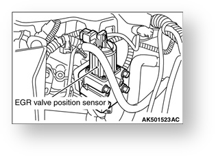
EGR Valve (DC Motor)
The EGR valve is located in the middle of the bypass that recirculates exhaust gasfrom the exhaust manifold into the intake manifold. It utilizes a DC motor in order to control the opening and closing of the valve in accordance with the changes in direction of the electrical current.
Freeze Frame Data
When the engine-ECU detects a problem and stores the resulting diagnosis code, the engine condition at that time is also memorized. The M.U.T.-III can then be used to analyze this data in order to increase the effectiveness of troubleshooting. The freeze-frame data display items are given below.
| Item No. | Data | Unit |
|---|---|---|
| 2 | Ignition Cycle | - |
| 4 | Accumulated Minute | min |
Data List FunctionDiagnostic System
The data list items are given in the table below
Item No. | Inspection item | Unit |
|---|---|---|
1 | Battery voltage | V |
2 | Engine revolution | r/min |
3 | Target idle speed | r/min |
4 | Vehicle speed sensor | km/h |
5 | Barometric pressure sensor | kPa |
6 | Manifold absolute pressure sensor | kPa |
7 | Engine coolant temperature sensor | °C |
8 | Intake air temperature sensor No. 2 | °C |
9 | Accelerator pedal position sensor (main) | mV |
10 | Accelerator pedal position sensor (sub) | mV |
11 | Accelerator pedal position sensor (main) | % |
12 | Accelerator pedal position sensor (sub) | % |
15 | Vehicle speed sensor | km/h |
16 | EGR valve position sensor | % |
17 | EGR valve target position | % |
21 | Fuel temperature sensor | °C |
25 | A/C switch | OFF/ON |
26 | A/C load signal | OFF/ON |
27 | A/C relay | OFF/ON |
28 | AT/MT switch | MT/AT |
29 | Condenser fan relay | OFF/ON |
30 | Control relay | OFF/ON |
33 | Engine check lamp | OFF/ON |
35 | Glow lamp | OFF/ON |
36 | Glow plug relay | OFF/ON |
37 | Idle switch | OFF/ON |
38 | Ignition switch | OFF/ON |
40 | Starter switch | OFF/ON |
43 | Intake air temperature sensor No. 1 | °C |
45 | Throttle position sensor | mV |
47 | Throttle position sensor | deg |
56 | Engine revolution | r/min |
63 | Rail pressure sensor | MPa |
64 | Rail pressure target | MPa |
66 | Supply pump learned value | mA |
72 | First shift switch <M/T> | OFF/ON |
73 | Reverse shift switch <M/T> | OFF/ON |
75 | Power steering fluid switch | OFF/ON |
76 | PTC heater 1 relay <vehicle with PTC heater> | OFF/ON |
77 | PTC heater 2 relay <vehicle with PTC heater> | OFF/ON |
114 | Air flow sensor | mg/cyl |
152 | Fuel filter pressure switch | OFF/ON |
Engine-ECU Monitor Items
- Items useful for grasping the engine control condition by the engine-ECU are provided in this monitor item section.
- Values of these monitor items vary greatly depending on marginal difference of measurement conditions, difference of the environment, aged deterioration of vehicles and so on, and it is difficult to show the precise specification values. Therefore, check conditions, display range and movement of values are described.
Item No. | Inspection item | Display range, numerical value |
|---|---|---|
13 | Accelerator pedal position sensor (main) learned closed position | mV |
46 | Throttle position sensor learned closed position | deg |
57 | Fuel quantity final | mm3/st |
58 | Fuel quantity pilot | mm3/st |
59 | Fuel quantity smoke limit | mm3/st |
60 | Fuel quantity start | mm3/st |
61 | Fuel injection interval pilot | us |
62 | Fuel injection timing main | CA |
65 | Supply pump learned status | * |
78 | Small injection quantity at pressure 1 - No. 1 cylinder | ms |
79 | Small injection quantity at pressure 1 - No. 2 cylinder | ms |
80 | Small injection quantity at pressure 1 - No. 3 cylinder | ms |
81 | Small injection quantity at pressure 1 - No. 4 cylinder | ms |
82 | Small injection quantity at pressure 2 - No. 1 cylinder | ms |
83 | Small injection quantity at pressure 2 - No. 2 cylinder | ms |
84 | Small injection quantity at pressure 2 - No. 3 cylinder | ms |
85 | Small injection quantity at pressure 2 - No. 4 cylinder | ms |
86 | Small injection quantity at pressure 3 - No. 1 cylinder | ms |
87 | Small injection quantity at pressure 3 - No. 2 cylinder | ms |
88 | Small injection quantity at pressure 3 - No. 3 cylinder | ms |
89 | Small injection quantity at pressure 3 - No. 4 cylinder | ms |
90 | Small injection quantity at pressure 4 - No. 1 cylinder | ms |
91 | Small injection quantity at pressure 4 - No. 2 cylinder | ms |
92 | Small injection quantity at pressure 4 - No. 3 cylinder | ms |
93 | Small injection quantity at pressure 4 - No. 4 cylinder | ms |
94 | Small injection quantity at pressure 5 - No. 1 cylinder | ms |
95 | Small injection quantity at pressure 5 - No. 2 cylinder | ms |
96 | Small injection quantity at pressure 5 - No. 3 cylinder | ms |
97 | Small injection quantity at pressure 5 - No. 4 cylinder | ms |
106 | Idle speed control torque | Nm |
Actuator Test Functions
Item | Inspection item | Value to be determined as normal |
|---|---|---|
1 | Engine check lamp | The engine check lamp turns ON |
2 | Glow lamp | The glow lamp turns ON |
3 | Glow relay | The glow plug relay ON |
4 | A/C relay | The A/C compressor clutch makes an audible sound |
5 | Condenser fan relay | Drive the fan motor |
15 | Injector No. 1 | Cut fuel to No. 1 injector |
16 | Injector No. 2 | Cut fuel to No. 2 injector |
17 | Injector No. 3 | Cut fuel to No. 3 injector |
18 | Injector No. 4 | Cut fuel to No. 4 injector |
19 | Suction control valve | Drive the suction control valve |
25 | EGR valve (0% open) | The EGR valve fully closes |
26 | EGR valve (50% open) | The EGR valve opens in half |
27 | EGR valve (100% open) | The EGR valve fully opens |
28 | Throttle valve (0 degree open) | The throttle valve fully closes |
29 | Throttle valve (45 degree open) | The throttle valve opens roughly in half |
30 | Throttle valve (90 degree open) | The throttle valve fully opens |
Table of Contents