Mitsubishi Diesel Auto Stop and Go Wiring/Programming (2012+)
- Brandyn Mowat
Mitsubishi Diesel How To: Auto Stop and Go Wiring/Programming (2012+)
Wiring Info
ASX
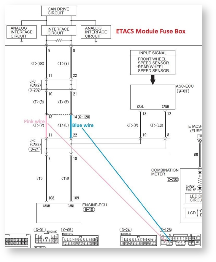
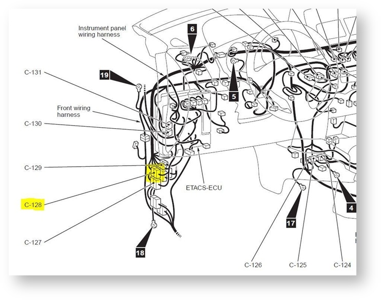
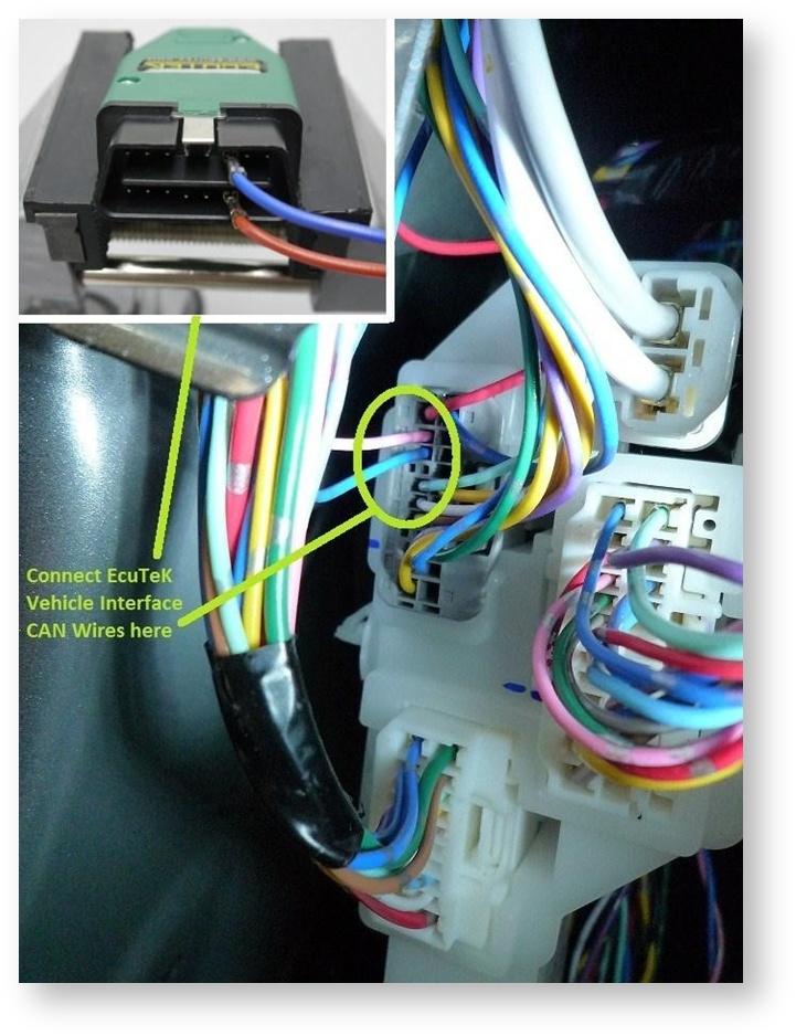
This image shows that we need to connect to pin 13 and pin 14 on the C-128 connector. The C-128 connector can be accessed in the side kick panel below the ETACS Fuse Board. This is Drivers side on Left Hand Drive (LHD) and passenger side on Right Hand Drive (RHD) models.
Pin 13 on the C-128 connector is CAN high.
Pin 14 on the C-128 connector is CAN low.
Knowing what the pins on the EcuTek vehicle interface are we can determine what items connect where.
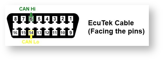
| EcuTek Vehicle Interface | C-128 Connector |
|---|---|
| Pin 6 | Pin 13 (CAN High) |
| Pin 14 | Pin 14 (CAN Low) |
The above picture shows the connector on a 2012 ASX model. Please note that the wire colours may be different on another model or year.
Mitsubishi Outlander 1.8 & 2.2 litre models
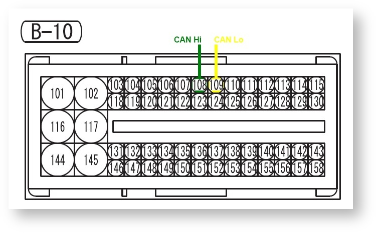
These models have different wiring to the ASX, so the CAN wires need to be connected directly to the ECU connector pins 108 and 109 on the B-10 connector.
To wire the Mitsubishi ECU on the bench you’ll need a 12V 5A power supply to provide power to the ECU. The only difference between this connector and the previous diagram is that you have to connect the ground wires to the EcuTek Interface Cable, and Pins 101, 103 and 104 to the 12V power supply. Power supplies lower than 5A may cause damage to the ECU or cause problems with programming.
The wires will have to connect directly to the ECU pins, so please make sure the crimp terminals are well insulated and do not short against other exposed pins. This may cause damage to your ECU. We suggest using a small length of heat shrink tube to insulate any bare metal of the terminal.
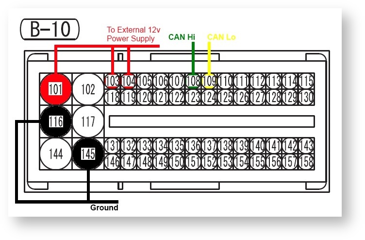
You'll need to connect to the ground on the EcuTek cable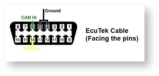
| EcuTek Vehicle Interface | B-10 Connector | Power Supply |
|---|---|---|
| Pin 101 Power | Power Supply Power | |
| Pin 103 Power | Power Supply Power | |
| Pin 104 Power | Power Supply Power | |
| Pin 4 Ground | Pin 116&145 Ground | Power Supply Ground |
| Pin 5 Ground | Pin 116&145 Ground | Power Supply Ground |
| Pin 6 Can Hi | Pin 108 Can Hi | |
| Pin 14 Can Low | Pin 109 Can Low |
Once this is completed you can use ProECU to detect the ECU as you would normally, this will circumvent the ETACS ECU completely.
Programming the ECU
Once the wiring connections are made direct to the CAN bus, the ECU can be programmed or restarted as desired. Data logging and Read/Clear DTC can be made from either the OBD2 socket or the temporary wiring connection onto the CAN bus.