Mazda DISI Tuning Guide
- Brandyn Mowat

Mazda DISI ProECU Tuning Guide
Accelerator
Primary Torque control is done using the Throttle Butterfly position.
The Mazda DISI uses the driver input (via the Accelerator pedal) to determine the required or desired Engine Torque for a current Throttle Angle and Engine Speed. The Throttle Butterfly is then driven open to the calibrated butterfly angle. Other factors can then limit the actual amount of butterfly opening angle. Maps which can effect or limit the Throttle Opening amount (therefore the airflow/torque restriction) are:
3D map: Maximum Allowed Torque
3D map: Desired Torque to Throttle Angle
3D map: Torque Reduction per Gear
3D map: Desired Engine Load
3D map: Engine Load to Throttle Angle
3D map: Engine Load Limit
2D map: Engine Load Limiter 1-6
Take care when changing the 3D maps for Engine Load to Throttle Angle and Desired Torque to Throttle Angle, as they are carefully calibrated and big changes can destroy the drivability of the standard vehicle (especially the Front Wheel Drive 3MPS that struggles with wheel spin as a standard).
We suggest that you start with our ‘Example ROM’ which already has modified Torque to Throttle control and Desired Engine Load maps. Our modified Example maps work well and offer Increased Torque Output for a said Accel pedal position (allowing the throttle to open further). Further modifications to the example maps should not really be needed and risk drivability issues.
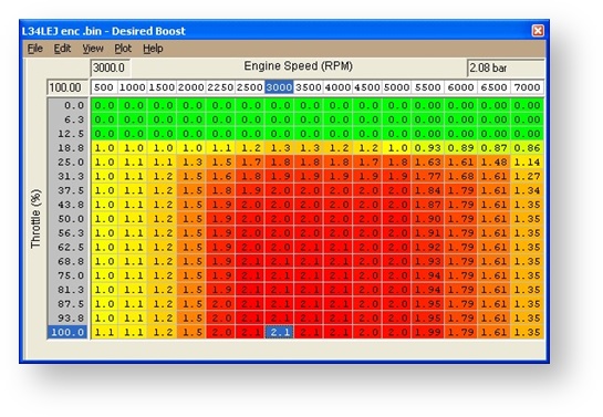
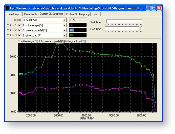
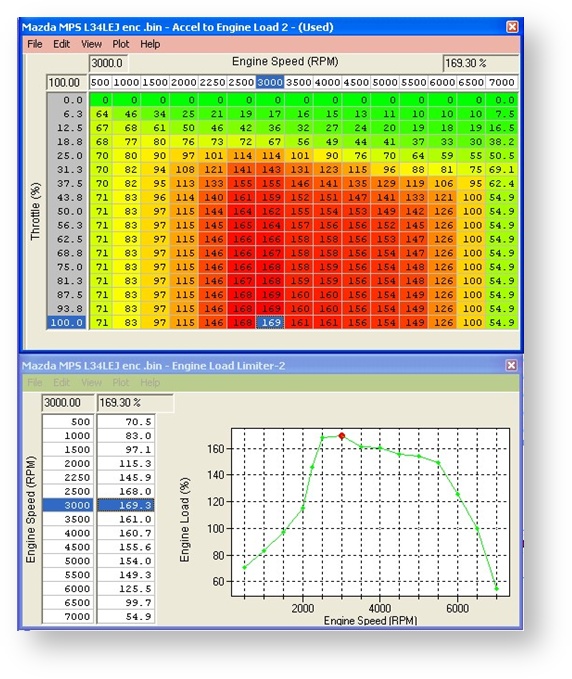
The standard 3MPS ROM does not fully open the throttle butterfly. If the Throttle control maps are modified to allow full Butterfly Opening no power increase will be seen or recorded. As below you can see the Maximum Desired Engine Load is 169% (around 2.08 bar boost absolute on the 3D Desired Boost map).
The 3 MPS has heavy Torque reduction in the first 4 gears due to wheel spin. Removing these limiters will produce lots of wheel spin, it’s suggested that they are raised slightly but not completely removed. Mazda 6 can be raised as 4wheel drive provides ample traction.
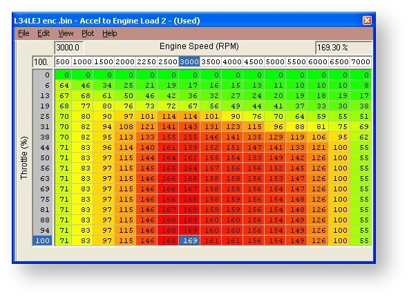
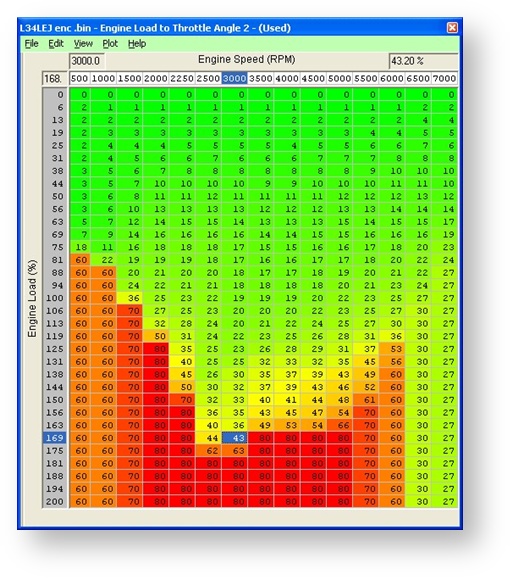
For a desired Engine Load of 169% the ECU will open the Throttle Butterfly to around 43%
(look up from the 3D Engine Load to Throttle Angle map). This is assuming that the
Maximum Allowed Torque value does not limit the throttle opening against the Desired Torque to Throttle Angle map)
Maps
Live Data Parameters
- Accelerator Pedal
- Accelerator Pedal Position #1
- Accelerator Pedal Position #2
- Accelerator Pedal Position Sensor #1
- Accelerator Pedal Position Sensor #2
- Throttle Angle
- Throttle Angle Actual
- Throttle Angle Desired
- Throttle Position #1
- Throttle Position #2
- Throttle Position Desired
- Throttle Position Sensor #1
- Throttle Position Sensor #2
- Throttle Voltage Lowest Closed
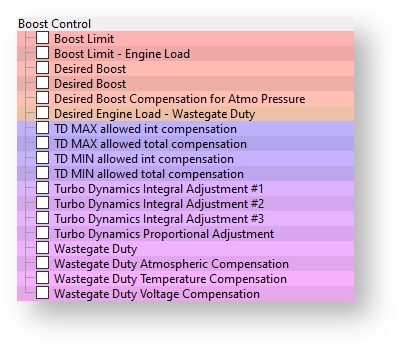
Boost Control
On Full Load the ECU uses a Full Throttle (W.O.T.) Target Boost map.
These values must be slightly higher than the 3D Desired Boost targets at 100% throttle or unstable boost will occur.
It is important to keep your wastegate duty values low, if your wastegate duty values are higher than the values the ECU actually needs to achieve a desired boost, then you will get unstable boost control. The unstable boost can easily be indentified in the log file as a zigzag wastegate duty action. In a simple form if you desired 2bar absolute and allow 80% wastegate duty but the ECU only uses 60% wastegate duty to make 2 bar absolute then you WILL get unstable boost. If you set the wastegate duty down to 40%, the ECU will increase the wastegate duty to around 60% using the Turbo Dynamics error compensation tables.
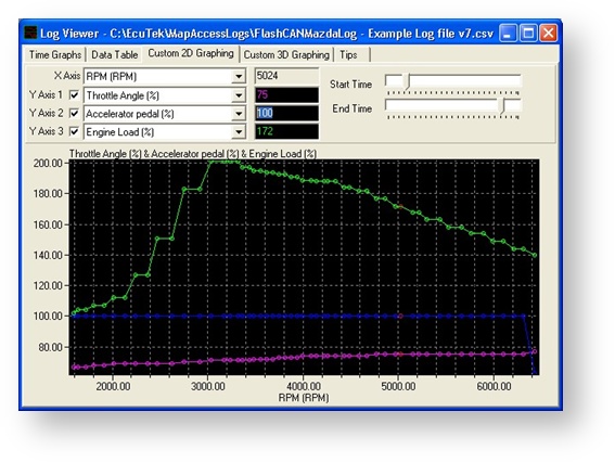
FACT: Just because the butterfly is only open 60% at 3000rpm does not mean the butterfly is
‘limiting’ engine torque output. By fully opening the throttle butterfly at peak torque (and low airspeed) on the standard vehicle produces no more torque than standard.
On a tuned ROM the restricted throttle opening WILL limit the engine torque output so our Example ROMs again have been carefully recalibrated through many hours of testing, so start with our Example Maps and modify further if needed.
NOTE: Maximum Throttle Opening is 77%, which is also shown by the Mazda diagnostic tool. We never achieve FULL Throttle Opening around peak torque , it is quite normal to see around 70-77% as other factors are always trying to reduce the throttle Angle (like Air Temp, Charge Air Temp, Barometric pressure, Coolant temp etc)
Maps
Live Data Parameters
- Atmospheric Pressure
- Boost
- Wastegate Duty Cycle
- Manifold Absolute Pressure
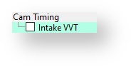
Camshaft Timing
This map controls the angle of the intake cam (note that 1 degree at the camshaft is 2 degrees at the crankshaft). This number is in camshaft degrees before Top Dead Centre. Modifying the cam timing map can increase power and turbo response, but too much advance can significantly increase in cylinder pressures. This is dependent on Camshafts, Turbocharger and naturally any item which will change.
Maps
Live Data Parameters
- VVT Intake Actual
- VVT Intake Desired
- VVT Intake Error
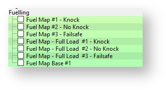
Fuelling
The fuel maps contain target AFR data, based on RPM and calculated engine load. When altering fuel maps, bear in mind that the AFRs are only theoretical, they are calculated AFR.
The ECU will generally strive to achieve a target AFR of 14.7 (or Lambda 1) during Closed
Loop conditions (normally up to about 1 or 1.2 bar absolute pressure). Once above this Low Load – Closed Loop status the ECU will be in High Load without holding 14.7 (or Lambda) closed Loop control. Different and more favourable AFR targets can then be specified but take care as quality of the feedback control from the stock AF sensor is still not trustworthy , always use your own wideband sensor to verify any AFR readings. Changing something simple like Fuel pressure from say 3.0Bar to 4.0Bar would make the fuel table inaccurate, bear this in mind.
Fuel Map – Full Load
This is the Full throttle desired AFR, changing the 3D Fuel maps will not affect the Full Throttle AFR target.
Injector Scaling
Not needed due to the fact the MPS uses High Pressure Direct Injection.
Maps
Live Data Parameters
- AFR
- AFR Desired
- Fuel Pressure
- Fuel Rail Pressure
- Fuel Trim Long Term
- Fuel Trim Short Term
- O2 Rear Sensor Fuel Trim
- O2 Sensor Current
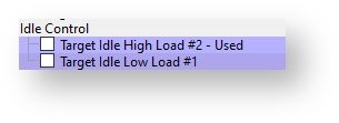
Idle
Idle Speed
These maps define the desired Idle Speed against coolant temp.
Maps
Live Data Parameters
- Engine Speed
- Engine Speed Desired
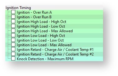
Ignition
These maps contain the ignition timing values, based on RPM and calculated engine load. Detonation should always be listened for, as the ECU will remove Ignition timing if detonation occurs. This is shown under Live Data in Ignition Degrees as the Knock Retard value.
The ECU has two defined Ignition zones, Low Load and High Load.
Low Load can generally be defined as light throttle up to around 1.2bar Absolute pressure, generally speaking in the Closed Loop AFR control with A/F Correction active.
High Load can generally be defined as over 40% throttle opening in Open Loop mode and over 1.2bar Absolute pressure (AF Correction not active).
Both Ignition maps should always be set the same. Map A is generally used but Map B can be used in other Engine Modes like Cold Start or Hot restart.
Maximum Allowed Ignition maps should not need to be altered.
It is advised to set both pairs of Ignition map the same if this is how the stock ROM is configured.
If Ignition maps ‘High Load - High Oct’ and ‘High Load - Low Oct’ are the same then keep them the same.
They may be different in some regions and Ignition maps labelled ‘Low Oct’ can actually be used as Base Ignition map climbing to the corresponding ‘High Oct’ map if no knocking occurs, so watch closely.
Always verify your Ignition timing shown in your log file against your Ignition Timing in your ROM as below:
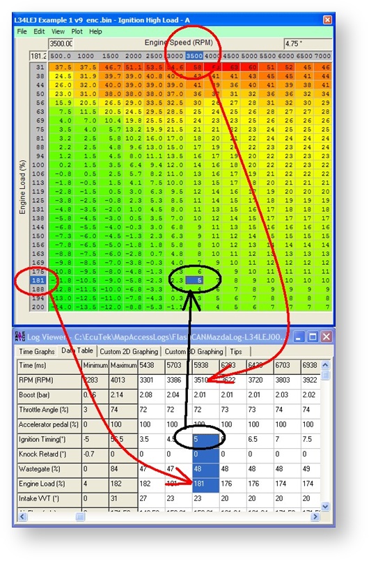
If you have more Ignition timing than the ECU will actually use then it may be capped by the Maximum Allowed Ignition map, so even if you fill the High Load or Low Load Ignition maps with 45deg (for example only) then you will only seen whatever is in the Maximum Allowed Ignition map.
Detonation should be checked for using an Engine Knock listening device or a stethoscope, as the standard Knock Sensor may not actually detect all different knock frequencies on an engine with modified parts. The standard Knock Control does seem to work quite well and a generous amount of AFR Enrichment is also applied to help ‘quench’ any knock activity when it occurs.
It is not unusual to see active knock correction on the dyno especially in warmer climates.
Maps
Live Data Parameters
- Ignition Timing
- Knock Correction
Limiters
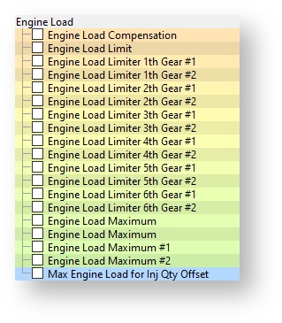
Engine Load Limiter 1- 6
This is the maximum Allowed Engine Load (%). If you increase boost, airflow or torque values then theses 2D maps will cap the Engine Load and close the throttle.
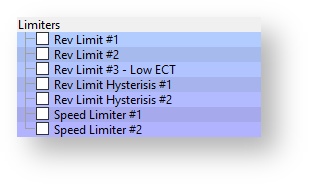
Rev Limit
The Engine Speed at which the ECU will cut the Fuel Injectors
Maps
Live Data Parameters
- Engine Speed
- Vehicle Speed
- Engine Load
Load
Desired Engine Load 1 - 3
Engine Torque (Airflow/Boost Pressure) is managed by the ‘Desired Engine Load’ maps. The desired Engine Load targets at light throttle are quite often much higher than can actually be achieved due to restricted Throttle Butterfly Angles calibrated in the Engine Load to Throttle Angle map.
You can roughly work out your current Engine BHP by your MAXIMUM Mass Air Flow reading (in grams per second). The standard mass Air Flow on a 3 MPS is 215 g/s, 210*1.25 = 262BHP, our example ROM makes around 236 g/s so this is around 295 BHP. This simple multiplication can be used on all vehicles that can show Mass Air Flow, try it, it works every time (assuming you have a standard or stock air Intake). This is also an easy way to spot a contaminated MAF sensor (by comparing the MAP and MAF logs from other similar vehicles.
Maps
Live Data Parameters
- Engine Load
- Accelerator Position
- Mass Air Flow
Sensors
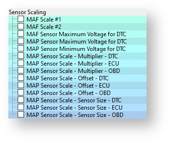
MAF Scaling
This map converts the Mass Air Flow sensor voltage into Airflow in grams per second.
It can be used to recalibrate the Engine Load after an Induction kit has been fitted.
Maps
Live Data Parameters
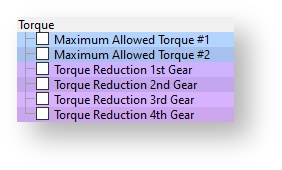
Torque
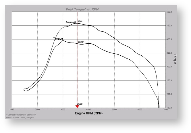
When performance testing the stock car remember there are Torque Reductions applied ‘Per Gear’.
As below there is a 10% reduction in 4th Gear and 20% in 3rd Gear.
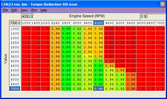
This can obviously make any Base test figures read lower than the factory quoted Power and Torque.
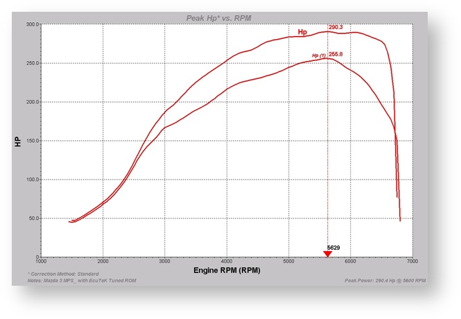
Mazda 3MPS is quoted at:
260PS (256bhp or 191Kw)
380NM Torque (280lbs.ft or 38.7kg)
Some tuners may choose to take advantage of this factory Torque Reduction in the lower gears when tuning a customer’s vehicle.
Providing ‘Before and After’ Power graph results where Dyno Testing is done in 3rd or 4th gear can show good gains once the ‘Per Gear’ Torque Reduction maps are raised Please note: That if you disable the DSC system (Traction Control) for your performance testing, then ‘Per Gear’ Torque Reduction is no longer applied.
Maps
Hints and Tips
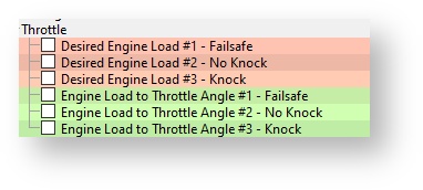
- Where multiple maps are shown (like 3D map called Desired Engine Load or Engine Load to Throttle Angle) you may find the ECU will swap between map 1 and 2. Map 3 normally has reduced values for a CEL condition. The ECU may swap between maps 1 and 2 for various reasons including Cold Start condition, EGR is active, TGV/Intake Runner Control is active, No VVT, High Altitude, Different Regions Calibrations etc. It is suggested that maps 1 and 2 are set the same and map 3 (CEL condition or Limp Mode) is left alone.
- Where multiple maps are available, ProECU shows which map is ‘normally’ used with a simple ‘-Used’ comment after the map description. It is still advised that all maps are set the same unless one map is clearly different and has been calibrated for a CEL condition.
- The standard 3MPS ROM files have been (kindly) scaled to around 200% Engine Load. So by just increasing the Desired Engine Load and Boost Pressure maps proportionally along with Boost Limits and Engine Load Limiters we can make pretty good tuning improvements.
- Make sure that your data logged Engine Load values do NOT exceed your 2D Torque Limit or 3D Maximum Allowed Engine Load. If Engine Load goes to high the ECU will start to close the throttle butterfly in an attempt to reduce the current engine torque.
- Mazda uses the Throttle Butterfly as an Engine Torque Limiter. Mazda does not rely on Wastegate Duty only to reduce the Engine Torque (Airflow/Power) around peak torque when you lift from the Accel pedal. The main reason for this is the throttle butterfly angle has very little effect on reducing the actual Engine Torque at low engine RPM (Low Air Speed). The Throttle Butterfly on the standard ROM is only open around 60% of a potential 70% to 78%. Allowing the Throttle Butterfly to open further (by adjusting the Engine Load to Throttle Angle AND Desired Torque to Throttle) to its full 75+% does not increase Airflow, Boost Pressure or BHP!
- In the ‘EcuTek Example ROMs’ Folder we have modified the Engine Load to Throttle Angle AND Desired Torque to Throttle maps as we now want to achieve a full throttle butterfly opening with a fully depressed Accel pedal for our higher Engine Load (raised from 160% to 205%) and higher Boost Pressure (2.0bar to 2.3bar)
- Watch for heat soak during dyno testing, the top mount Intercooler sits directly on top of the engine so gets very hot during ECU programming, we suggest you leave the Dyno Fans on during ECU programming. Once the engine has been restarted after programming drive the car at 2500rpm and around 30bhp and monitor the Charge Air Temp, wait until its around 10-15deg above Intake Air Temp before attempting a dyno run. The top mount intercooler sits directly on top of the engine and Charge Air suffers on Dyno runs, especially the 6MPS that does not have a Subaru Style air scoop !! This unrealistic rise in Charge Air Temp can cause knocking that will not occur on the road in real conditions so take care not to retard the Ignition too much or on road performance will suffer
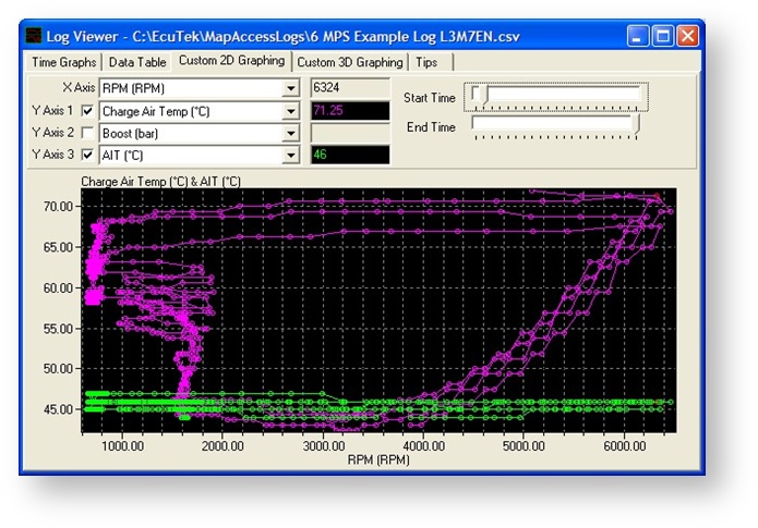
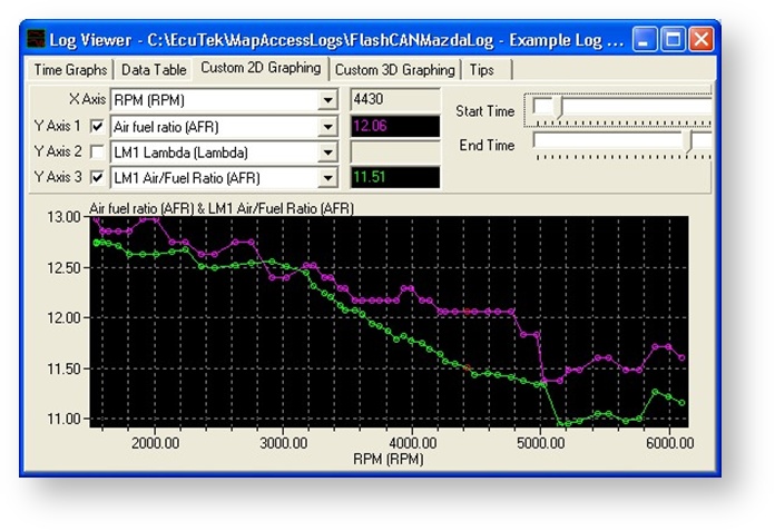
- AFR should always be checked with a wideband Lambda sensor. We suggest a target AFR of around 11.5:1 at peak torque (3500-4000rpm) dropping to around 11:1 by 6000rpm. The factory fitted wideband sensor should not be relied upon for open loop AFR tuning.
- You can see the difference in AFR readings (shown below). The LM1 shows a more accurate AFR reading and this was in a sample pipe in the exhaust tailpipe. You can also clearly see the Fuel Enrichment factor applied during knock at 5000RPM, this was basically due to high Charge Air Temp on the dyno. This did not occur on the road test afterwards.
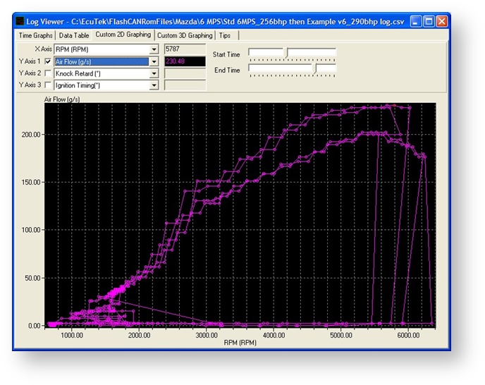
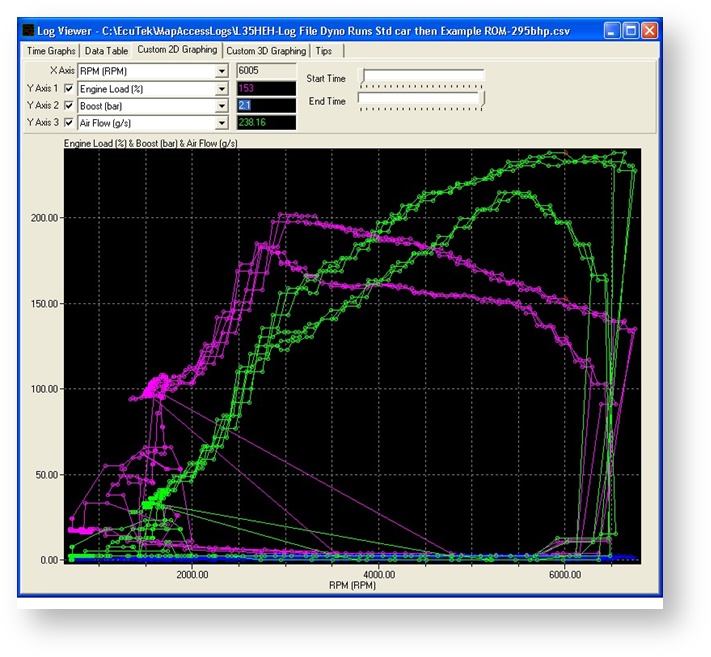
Typical Power Gains
The graph below shows Engine Load, Boost and Air Flow before and after tuning using EcuTek software:
EcuTek ProECU tuning tools tools should only be used by experienced tuners who understand the product and engine calibration.
If you do not fully understand this product then you WILL damage your engine, ECU or your vehicle.
Please ensure you fully read all EcuTek manuals BEFORE attempting to use ProECU with your laptop or your vehicle.
Use with extreme caution and understanding at all times, if in doubt then do not proceed.
EcuTek accepts no responsibility for any damage to the engine, ECU or any part of the vehicle that results directly or indirectly from using the product.
** If you are in any doubt that you do NOT have the experienced required to use this product then you should NOT USE IT **
Retail customers
** If you have any doubt that you do NOT have the experienced required to use this product then you should NOT USE IT, you should simply contact your EcuTek Master Tuner shown clearly on the top of your Programming Kit or visit your preferred tuning shop to have a professional tuner to use it for you **