GT-R ProECU Tuning Guide
- Brandyn Mowat
GT-R ProECU Tuning Guide
Accelerator
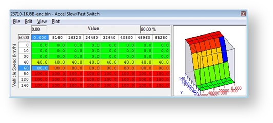
The Normal, Slow, Fast, Safe and Trustful Accel Maps define the ratio between the Accel Pedal % and throttle butterfly opening angle. The 3D map called Accel Slow/Fast Switch defines the vehicle speeds between the Accel Map, Normal Slow and Accel Map Normal Fast 2D maps. The below screenshot shows that the Accel Map Normal Slow map is used at lower vehicle speed (below 30kph)
Accel Map Normal Fast map is used at higher vehicle speeds (over 80kph), and 80% of the Accel Map Normal Fast map is used at 60 km/h (the other 20% is interpolated from the Accel Map Normal Slow map).
Alternate maps are used whilst in Safe Mode from the regular Normal Mode maps.
Always set the corresponding Trustful map the same as it's corresponding map
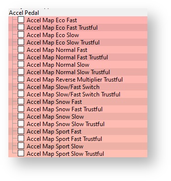
Map List
Live Data Parameters
- Accel Pedal
- Throttle Angle Bank #1 & #2
Throttle Body Tuning
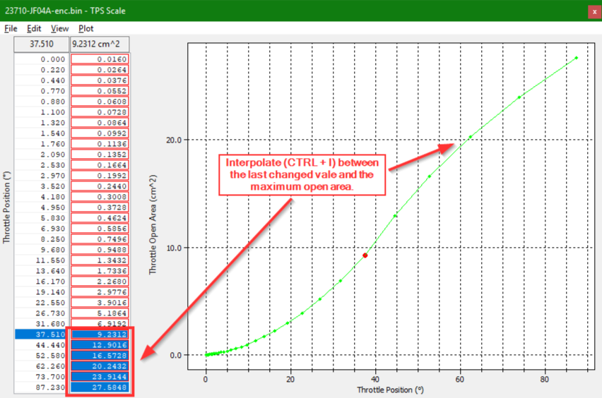
The Primary maps used to re-scale the throttle airflow requirements in Nissan vehicles are the Throttle Position Sensor (TPS) scale maps.
These maps relate throttle opening area to angle, and (in GTR) the scale goes from 0-27.585cm^2 column at angles from 0-87.23, by increasing the throttle area for the same angle, the ECU will know to open the throttle less for a given target airflow (throttle open area and pressure related).
Tuning a Bigger Throttle
Before you make any changes to the calibration its important to know the difference between the OEM and aftermarket throttles. The primary difference will be in diameter, the OEM throttle bodies are 60mm diameter and most of the aftermarket units are 68-73mm. What we need to know id the percentage change in open area between the OEM and After market throttles. this is done by calculating the difference in area (or diameter squared).
Percentage Difference in Area = (New Throttle Body Diameter)^2 / (Old Throttle Diameter)^2
e.g. 68^2 (Greddy)/ 60^2(stock) = 1.28
The first tuning step is to go to the TPS Scale Map and adjust the throttle open area by the increased percentage area difference, However, due to the 60cm^2 limit we cannot increase all of the values in the map we must go up to nearly below full open angle and blend appropriately. In the example we would modify as follows, First scale up the map by the desired amount
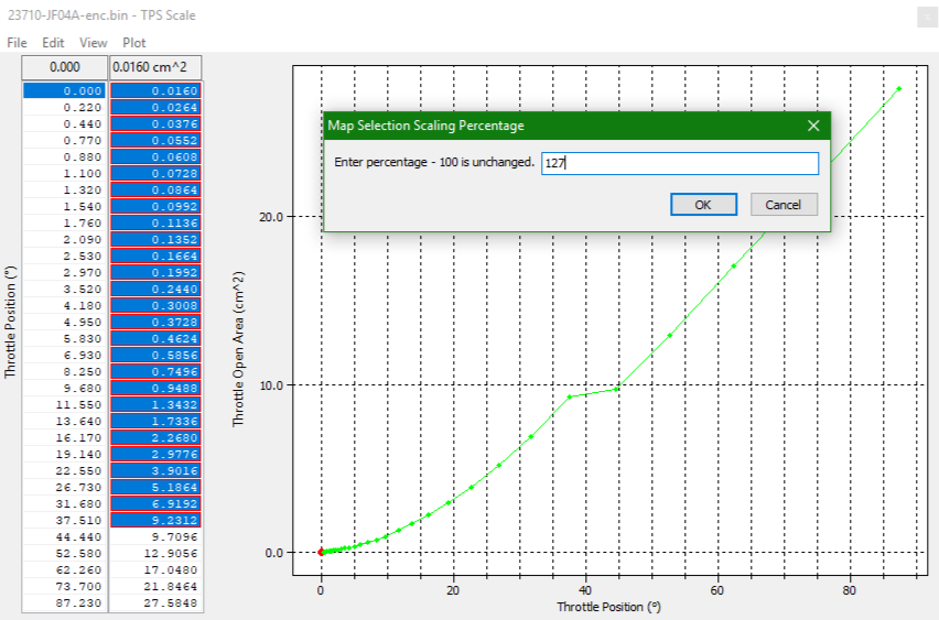
then Blend the map so that it does not give a rapid drop but the last value is still the same as OEM
Once the maps has been scaled correctly you must copy the map and paste it to the TPS Scale Trustful map to ensure they are identical.
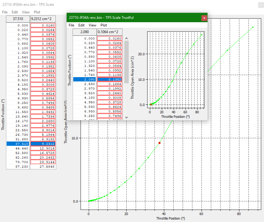
There are some OEM code number limits that restrict the maximum values in the calculation function. If you scale the values above 27mm^2 the throttle will close at high loads when the throttle area demand cant go above this value.
If the trustful and actual map do not match exactly you will receive a P0605 error code.
Idle Airflow Maps
Depending what other modifications have been made to the car the idle airflow targets may need to be adjusted. If the vehicle is stalling idling erratically or not recovering from overrun conditions you may need to use the idle airflow target maps (for drive and neutral and 2 different modes).
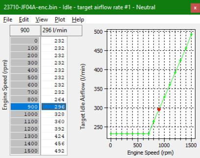
It would be good practice to make the airflow target match the actual airflow consumed when idling in both Neutral ad drive, simply log the mass airflow in both situations and set the maps to be the same amount. There are unit converters available for converting from l/min to g/sec but at at 300l/min it converts to roughly 5.8g/sec.
You may also want to increase the idle airflow target to try stop the RPM dip on overrun.
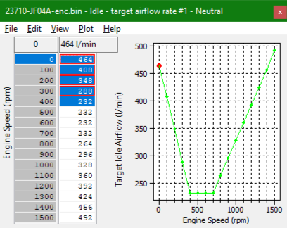
It may also require raising throttle angle limits but generally when increase throttle size you will require less angle for the same airflow so they shouldn't need lifting.
Special Note
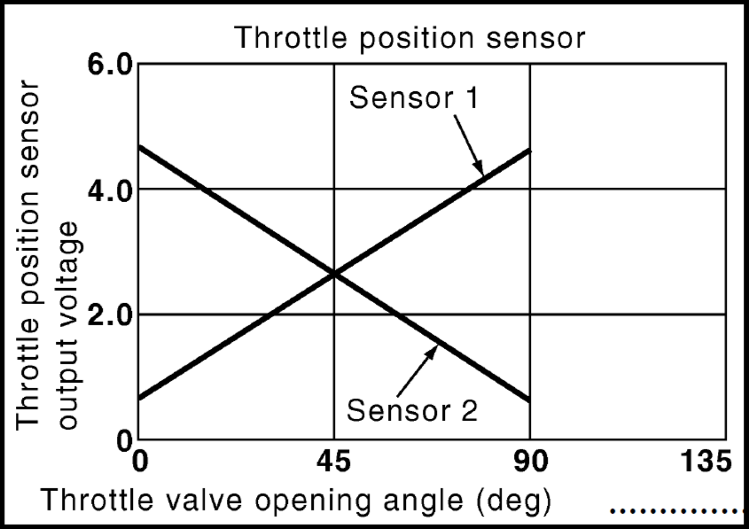
While you can change the throttle plate diameter the throttle position sensor characteristics cannot be changed, the A/D conversion performed inside the ECU has not been dissembled to a level to allow this. It must be the same as the throttle position voltages below otherwise DTC's will occur.
Boost Control
EcuTek have rewritten the entire GTR Boost Control system for the Phase 5 and later Feature File updates. For more information refer to the RaceROM Tuning Guide. We do NOT recommend the factory boost control maps be used for tuning.To use the Phase 5 and later RaceROM Boost Control ensure that the Enable EcuTek Boost Control box is checked in the Enable Special Features window once checked the OEM Boost Control Maps will no longer work. Information on that system can be found in our GT-R RaceROM Boost Control
Factory Boost Control – Not Recommended
The factory boost control on the GTR is very clever even though it can appear complex at first glance.
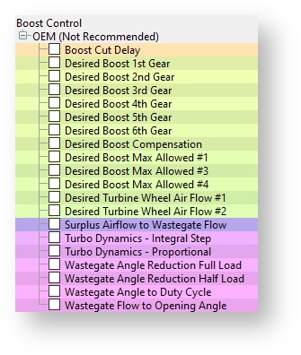
EcuTek have spent many many hours on hard disassembly to understand the factory boost control strategy. Spend some time to look through the various boost control maps to understand the various limiters and airflow control logic. Below is a description of each of the important boost control maps.
Map List
Live Data Parameters
- Boost B1/B2
- RBC Maximum Desired Boost
- Boost Target
- Boost Error
- Manifold Relative Pressure (Intake Manifold sensor)
- Desired Turbine Wheel Airflow
- Calculated Airflow
- Turbo Dynamics Proportional
- Turbo Dynamics Integral
- Turbo Dynamics Sum
- Surplus Airflow
- Desired Wastegate Flow
- Wastegate Angle Initial
- Wastegate Angle Correction
- Wastegate Angle
Boost Target
Shows the target boost pressure to try and achieve for an Accel Pedal position and Engine Speed.
Boost Target Max Allowed
This allows you to reduce the target boost pressure depending on the coolant temperature.
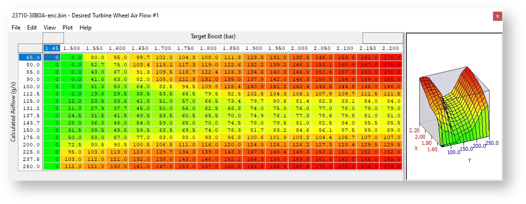
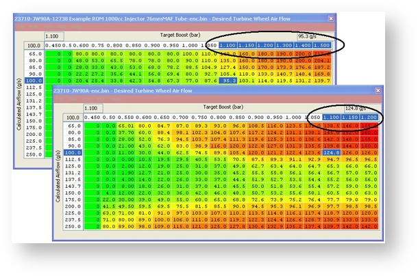
Desired Turbine Wheel Airflow
This map must be calibrated to the characteristics of the turbo. Once set, desired boost can be adjusted via the Desired Boost map. This map will need to be modified if larger turbos are fitted. It will also need to be modified if the flow of the exhaust, intakes or intercooler are improved.
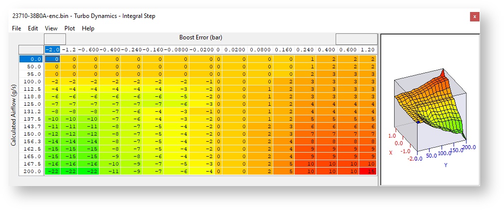
Turbo Dynamics - Integral Step
This shows the Integral component value added to output of the Surplus Airflow value in proportion to the size of the current boost error. Note the factory map does very little to correct a boost error at lower airflow! (It only corrects midrange boost error). Only at higher airflow will the factory Integral values make a reasonable adjustment to wastegate duty correction.
Raising these values too high will make the boost unstable.
This Integral value is continuously added for any boost error.
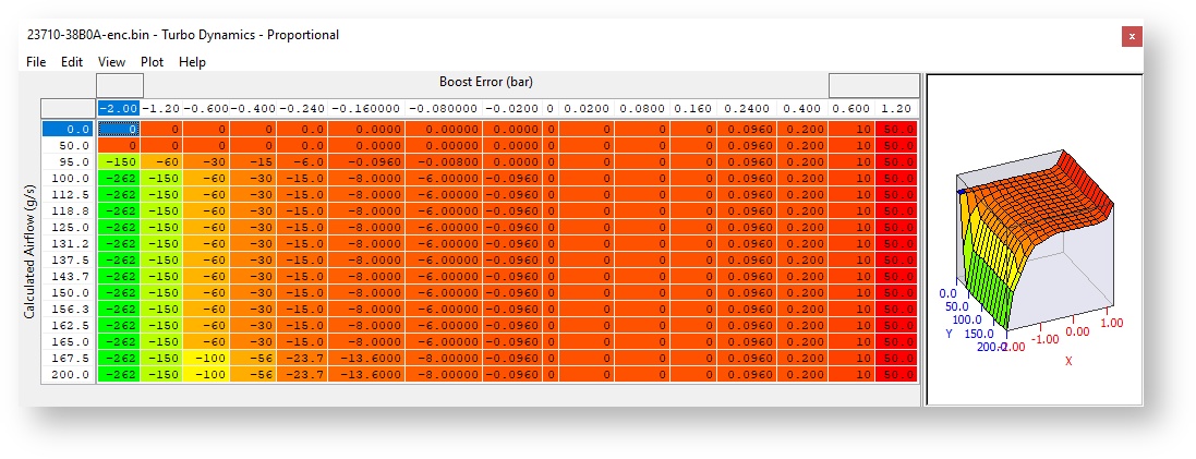
Turbo Dynamics - Proportional
This shows the Proportional component value added to output of the Surplus Airflow value in proportion to the size of the current boost error. Note the factory map does very little to correct a boost error at lower airflow! (It only corrects midrange boost error). Only at higher airflow will the factory Proportional values make a reasonable adjustment to wastegate duty correction. Raising these values too high will make the boost unstable. The Proportional value is a fixed value correction that is added to the Surplus Airflow and this will not increment like the Integral value.
Turbo Dynamics – Sum
This Live Data parameter shows the Integral and proportional components combined addition. Consistently high positive values suggest the Desired Turbine Wheel Airflow (DTWA) values should be reduced (overboost condition), negative values suggest Target Boost is not reached and DTWA values should be increased to reach the Target Boost.
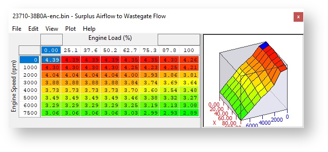
Surplus Airflow to Wastegate Flow
The surplus Mass Airflow is multiplied by a value from this map in order to calculate the flow rate of exhaust gas that must be vented through the wastegate. This map may need to be modified if larger turbos are fitted, as the relationship between exhaust gas flow and pre turbo exhaust gas pressure will vary.
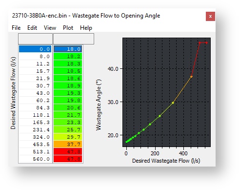
Wastegate Flow to Opening Angle
Once the required wastegate airflow is known, this map calculates the wastegate opening angle required to vent the desired flow. This map is calibrated to reflect the characteristics of the wastegate orifice. You only need to modify this map if you port the wastegate orifice.
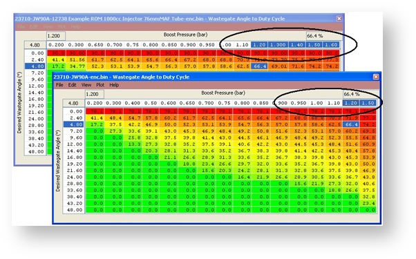
Wastegate Angle to Duty Cycle
This map is the final wastegate duty that will be used by the ECU depending on the current boost pressure and the desired wastegate valve angle. These values can be reduced by 50%+ on vehicles fitted with stronger actuators (1bar+) and/or larger turbos.
Converts desired wastegate opening angle to the wastegate duty required. Values vary with the current boost pressure, since the pressure feed to the actuator diaphragm is fed from the boost pressure. So for a higher boost pressure, a higher wastegate duty (bleed off) is required to maintain the correct opening angle. You only need to modify this map if you replace the wastegate actuator or alter the spring tension.
If correctly understood and calibrated the boost control will be extremely competent.
In our experience using the RaceROM Boost Controller we can accurately recalibrate the boost control for different pressures with precision calculations and detailed log files to cross reference.
In the majority of cases the only map that should be altered is the Desired Turbine Wheel Air Flow map. Following the steps below will enable you to make accurate boost control calibration.
- Make a log at 0.8 bar, 1 bar and 1.2 bar (assuming you are able to run these different pressures without risk of damage to the engine) be sure to include all the important parameters used in boost control as listed in Live Data section (like Calculated Airflow, Wastegate Angle and Turbo Dynamics)
- Compare Target Boost and Boost Error and Calculated Airflow. By opening the Desired Turbine Wheel Air Flow map you can now see the corresponding Target Boost and Calc Airflow lookup parameter and this can be verified as the diagnostic parameter called Desired Turbine Wheel Output.
- If the boost is under target then the Desired Turbine Wheel Air Flow values needed to maintain the turbine speed are too low (and hence the boost is low), so simply raise the values to increase the amount of airflow that will hit the turbine wheel and increase turbo speed!
- The same procedure can be applied for an over boost situation.
- For greater accuracy set both Turbo Dynamics Integral and Proportional to Zero during boost calibration.
A final boost tuning tip is if your Target Boost is 0.8 bar and you generate a steady 1 bar then simply copy and paste the Desired Turbine Wheel Air Flow column for 0.8bar into the 1 bar column! This can be repeated for other boost targets as well.
We also advise that you start your tuning based on any EcuTek example ROMs where available. The example ROMs have the Desired Turbine Wheel Air Flow maps calibrated and in addition the X axis rescaled for greater resolution at higher RPM.
Boost Limit (RaceROM) and Boost Limit Resume (RaceROM)
The ECU will cut the Fuel Injectors if the Boost pressure (in Bar Absolute) exceeds the value in the Boost Limit map for a given atmospheric pressure. The Fuel Injectors will restore at the corresponding pressure shown in the Boost Limit Resume map.
The factory maps called Desired Boost and Desired Boost compensation are no longer used.The factory maps called Desired Boost and Desired Boost compensation are no longer used.
Camshaft Timing
Intake VVT
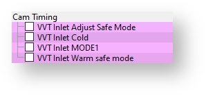
These four maps (MODE1 to MODE4) control the angle of the intake cam (note that 1 degree at the camshaft is 2 degrees at the crankshaft). This number is in camshaft degrees before Top Dead Centre.
The RaceROM Map Switching feature allows you to define multiple different calibrations in the ECU ROM. A separate Inlet VVT map is provided for each mode.
Modifying the cam timing map can increase power and turbo response, but too much advance can significantly increase in cylinder pressures. This is dependent on Camshafts, Turbocharger and naturally any item which will change. Increasing to 28-32 deg will significantly improve turbo spool at low rpm.
Map List
Live Data Parameters
- Intake VVT Bank #1 & #2
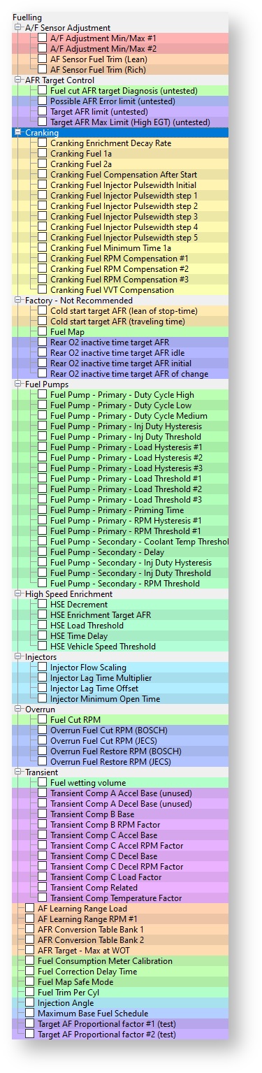
Fuelling
The Nissan GTR fuel control is fully closed loop from Idle all the way to the rev limiter including light load and full load.
The logging parameter called AFR TARGET will show the current AFR the ECU is trying to achieve. EcuTek have converted the factory Nissan AF sensor voltage into a more useful logging parameter called AFR Sensor Bank 1 and AFR Sensor Bank 2.
Typically on a stage 1 car the AFR Sensor Bank 1 or 2 might show 12:1 AFR but independent Wideband sensors (like Motec PLM) will show a more truthful and accurate 11.5:1 AFR. We suggest you always verify your AFR with an aftermarket wideband sensor until you have enough experience to trust the standard sensor readings. The AFR shown will tend to be slightly leaner than the car runs but this can change with full decat exhaust and larger turbo’s (and higher EGT).
Fuel Trims
Increasing fuel pressure from say 3.0Bar to 4.0Bar will not change the AFR as the Short Term and Long Term Fuel Trim will compensate to achieve the Target AFR shown in the fuel map, so watch the Fuel Trims carefully.
Fitting a larger Intake MAF tube (stock 66mm to 76mm is a popular swap) will cause the Fuel Trims to compensate for the under reading MAF so ensure you watch the Fuel trims and rescale the MAF accordingly.
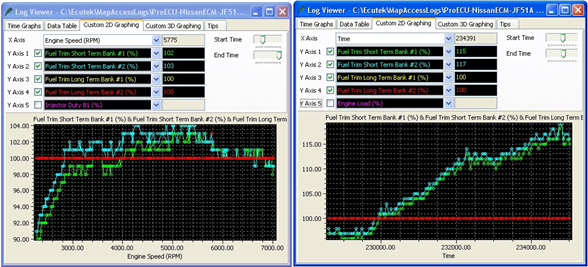
The short term fuel trim can add or subtract up to 25% (75% to 125%), the long term fuel trim can add or subtract up to 10% (90% to 110%). You should aim to keep the FT within 10% (90% to 110%) for a good calibration (ignoring transient movements), good calibration would be within 5% and the gearbox control will also show its appreciation.
Here are two examples of Fuel Trims in action, the left log file shows really good fuel trims but the right log file is adding +17% to the Injection Volume to achieve the target AFR. If this FT was 117% across the whole RPM range then the 1d MAF scale byte should be increased but as this is only at higher RPM then I could be a secondary fuel pump issue failing to deliver at higher RPM.
Fuel Injectors
The standard Injectors will be close to 100% open when running 1.1 bar boost at high rpm (6000rpm plus and 560bhp+) so watch carefully, a vehicle fitted with a full sport exhaust system running 1.2bar+ will max the injectors.
EcuTek can supply the high quality Bosch Motorsport Injectors that are 1050cc (good for 1000+ bhp), see them in the webstore.
The maximum Injector size you can enter in the factory map is 800cc, this is a limitation of the Nissan ROM code and not EcuTek.
For replacement Injectors over 800cc use the map called Injector Flow Scaling (RaceROM) you can choose a different Injector size for each of the map switch modes (useful for Ethanol tuning in different modes).
For more information on scaling fuel injectors using the OEM method check out our article Scaling Injectors For Nissan Using OEM Method (GT-R, 370z) or for information on RaceROM injector scaling visit GT-R RaceROM Injector Calibration
If the Injectors are to be replaced then choose at least 800cc plus. When fitting larger Injectors it’s important to reduce the Minimum Open Time from 1.8ms down to 1.2ms, otherwise 1.8ms on 1000cc Injectors will mean 12:1 AFR at Idle. Using the EcuTek 1015cc Injectors we typically run a 1.0ms Offset combined with a 975cc Injector size and we achieve very tight fuel trims.
Map List
Live Data Parameters
- AFR Sensor V (Volts)
- Air Fuel Ratio (AFR) #1 - #2
- Air Fuel Ratio Target
- Injector Pulse Width (ms)
- Fuel Trim Short Term (%) #1 - #2
- Fuel Trim Long Term (%) #1 - #2 Injector Duty #1 - #2
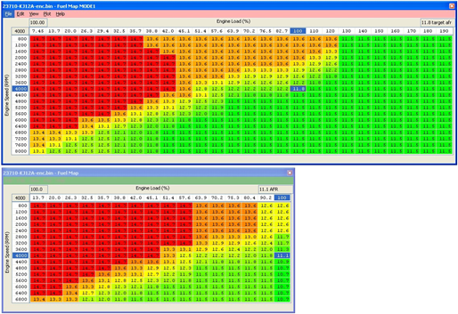
Fuel Map MODE1 to MODE4
The Nissan GTR fuel control is fully closed loop from Idle all the way to the rev limiter (including light load and full load). The fuel map contains an AFR TARGET based on Engine Speed (RPM) and Calculated Engine Load (%).
The vehicle has two factory fitted wideband sensors (one for bank 1 and another for bank 2). The ECU uses Fuel Trim Short Term Bank 1 and Bank 2 to ensure the target AFR is achieved. Further to this the Fuel Trim Long Term Bank 1 & 2 will make long term adaption trim for continuous Short Term Fuel Trim corrections.
The RaceROM Map Switching feature allows you to define four different calibrations in the ECU ROM. A separate fuel map is provided for each mode.
The four separate fuel maps are 26x19 in size providing 200% more resolution than the factory 16x16 fuel map (that is no longer used).
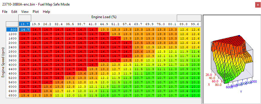
Fuel Map Safe Mode
This AFR target fuel map is used during Safe Mode.
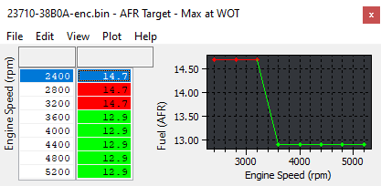
AFR Target – Max at WOT
This is the leanest AFR Target permitted for a given RPM when at WOT. Of the values returned by this map and the main 3d fuel map(s), the richest value will be used by the ECU. Raising the values in this map to prevents rich AFR Targets interfering with the intended target AFR typically used on high power cars with modified exhaust systems. Setting all the values in this map to 14.7 will completely disable the effect.
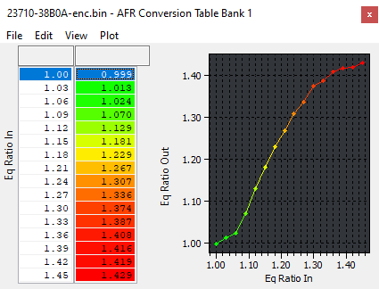
AFR Conversion Table B1/B2
These two maps (one for each bank) are used internally by the ECU to convert values in the main fuel map to bank specific AFR targets. The units are Equivalence Ratio and can be converted to AFR by dividing 14.7 by the values in the table, for example 1.00 gives an AFR of 14.7:1 and 1.336 gives an AFR of 11:1.
By default these tables do not give an output identical to the input, and it is different between each bank. The maps typically translate values from the fuel maps at high load to slightly richer targets. To nullify this effect, set that the data values to exactly equal the input values, but be aware that the result is that the reported AFR target and AFR logging parameter will not match when long and short term fuel trims are 100 (no trimming).
As the AFR logging parameters will generally read leaner than the actual AFR the vehicle runs we advise that a wideband sensor should always be used for accuracy if calibrating this table.
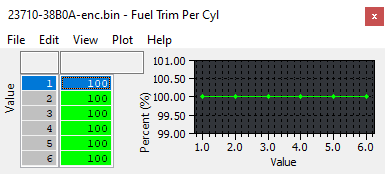
Fuel Trim Per Cylinder
This map can be used to add extra fuel to certain cylinders.
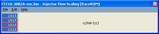
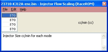
Injector Flow Scaling (RACEROM)
This map defines the injector size for each of the 4 different modes.
You can select Injector scaling values for each of the for Map Switch modes. This is useful if alternate fuels are used. When using E85 you can simply reduce the Injector scaling size by 30% and the fuelling will deliver +30% more injection volume.
The top value is MODE 1 the bottom value is MODE 4
If the Injectors are to be replaced then it's recommended to choose at least 800cc plus size injectors.
EcuTek can supply the high quality Bosch Motorsport Injectors that are 1050cc (good for 1000+bhp). They are tried and tested are not susceptible to some of the Idle and black smoke issues that some other brands do.
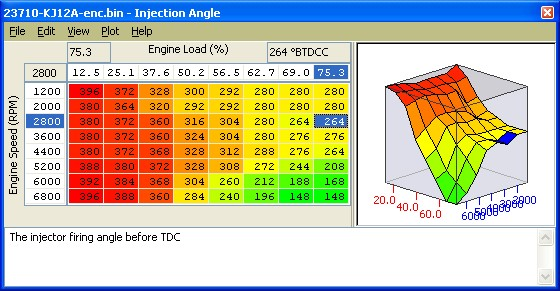
Injection Angle
This shows the injector firing angle before TDC, increasing these values by around 40-60deg during spool and peak torque can help avoid black smoke, this can become more apparent where larger injectors and more increased cam advance has been used.
Fuel Pump Control
The Primary Fuel Pump is controlled by the ECU as a 3 stage Duty Cycle that switches as a certain Engine Load% is achieved, the Primary – Duty Cycle Low (34%), Medium (67%) and High (100%), these duty value amounts can be altered in the top 3 maps shown below.
The Primary – Load Thresholds #1 – #3 can be used to alter the Engine Load at when the ECU switches between Low/Med/High. The factory setting have been configured so that during a full load pull the Duty steps from 34% to 100%, this can be altered using the threshold maps. Read the each individual maps HELP text to understand which Primary Load Threshold controls which control range.
The Secondary Fuel Pump is a simple ON/OFF switch and what is very important is that the 2nd fuel pump is switched ON against the Fuel Injector Open Time %. This is very important to change this when using larger Injectors, see the Tuning Sections for more info on recalibrating the 2nd Fuel Pump switch threshold.
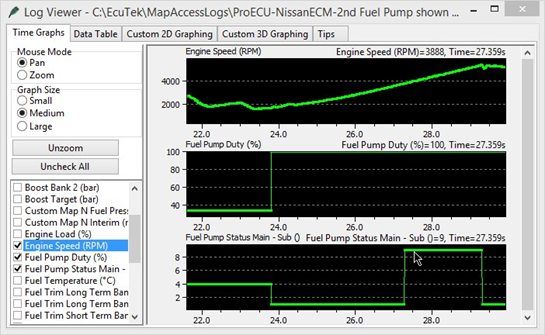
The logging parameter called Fuel Pump Status Main – Sub will show the current status of fuel pump control as shown below the status is:
- Fuel Pump Status 1 - Primary Pump High Duty
- Fuel Pump Status 4 - Primary Pump Low Duty
- Fuel Pump Status 9 – Primary Pump High and Secondary Pump ON
The Secondary Fuel Pump is only switched on when a certain Injector Duty is achieved (see the Fuel Pump Control section earlier in this manual for more information).
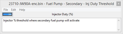
The 2nd Fuel Pump has been calibrated for stock 570cc injectors and the 2nd pump will activate around 2500rpm on full load (34% Injector Duty) BUT when fitting larger Injectors (1000cc for example) then the same Injector Duty will be around 3800rpm meaning the 2nd fuel pump switches on too late and the fuel rail pressure will start to as the Primary pump runs out of flow capacity!
So it is very important when fitting larger injectors that the Secondary Inj Duty% Threshold is reduced relative to the Fuel Injector size % increase otherwise the 2nd Pump will switch on too late and the fuel rail pressure will drop (as shown in the following log file screenshot).
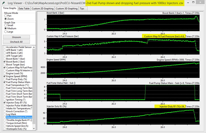
In this example a Fuel Pressure sensor has been imported through the Boost Sensor #1 and the Fuel Pressure is shown in the Log File as Custom Map N Output.
The GTR static fuel pressure at sea level is 4 bar (60psi), with 1 bar boost the fuel pressure should be 5 bar (75psi). During this power run you can see Boost Bank 2 climbing to 1 bar boost with the Fuel pressure climbing from 4 to 5 bar by 3000rpm but by 3500rpm the Primary pump has run out of capacity and rail pressure is starting to drop as low as 4.6bar during this dyno pull.
The 2nd pump finally kick in 3900rpm (34% Injector Duty) and the fuel pressure increases from 4.6 to 5.2bar and is regulated back down to 5bar.
Fuel Rail Pressure dropping as the 2nd Fuel Pump switches on too late!!
See Custom Maps manual for more information on importing pressure sensors and how to log and display on the setup Fuel Pressure sensor Fail Safes.
Ignition
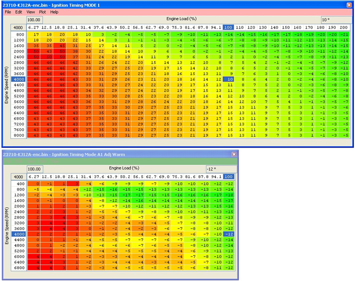
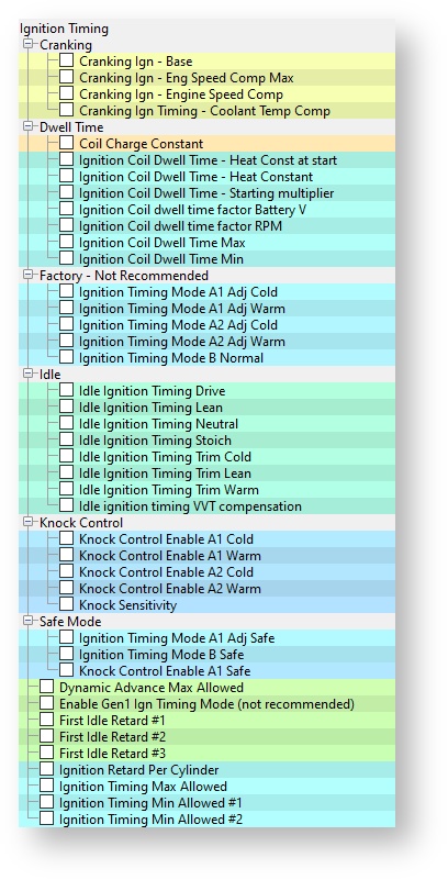
Ignition TIming MODE1 to MODE4
The map specifies ignition timing in degrees BTDC based on Engine Speed (RPM) and Calculated Engine Load (%).
The latest phase 3 or 4 RRFF (ver.12738 or newer) does not use the complex factory Mode A and B Ignition maps. These maps can be found under the category IGNITION TIMING > FACTORY - NOT RECOMENDED if an older RRFF version is being used.
The factory ignition maps have been replaced by four larger and more simplistic to understand versions and a map is provided for each of the four map switch modes (Mode 1- 4).
These superior Ignition maps offer the following advantages:
- Real Ignition Timing values.
- High-power high-resolution ignition maps rescaled for over 1000bhp.
- New 26x19 ignition maps provide 200% greater resolution than the stock 16x16 maps providing more accurate calibration at high RPM and high load.
- Up to 8000% more resolution over the stock Nissan map axis scaling providing unparalleled smoothness and drivability.
- Dynamic advance feature retained on Gen 2 models.
- Dedicated intake air temp compensation.
- Factory knock control retained, along with all other factory Ignition corrections.
- The Ignition Timing is calculated in the following order:
- Ignition Timing looked up from one of the four Ignition maps (Ignition Timing (MODE 1 to MODE 4) Ignition Timing Intake Air Temp compensation is applied (IAT)
- Other compensations and corrections are applied as normal (like cold start, gearshift, overrun, Idle and transient conditions).
- Knock Correction amount is applied and this can be retard as well as advance on Gen 2 models
Detonation should always be listened for even though the ECU will remove Ignition timing if detonation occurs. This is shown under Live Data in Ignition Degrees as the Knock Correction value.
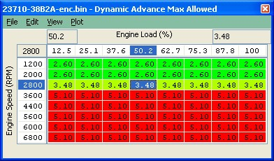
Dynamic Advance Gen 2 models
On Gen 2 models the Dynamic Advance map can be used to limit or increase the amount of positive advance that is added by the Knock Correction in the absence of any knock retard.
This can be an unwanted feature for most tuners so reducing these map values will prevent the ECU from Advancing the Ignition beyond the values shown in the RaceROM Ignition Timing maps.
In some regions there may be an offset value added or subtracted from these values.
Always watch and log the Knock Correction parameter as the ECU may add an additional +2 deg of Knock Correction on full load to over what is shown in the Dynamic Advance Max Allowed map, (the Euro region 38B6A does this)
So some regions may require -2deg in this map to stop the ECU actively adding any Ignition Correction though Knock Retard negative values will still work as expected.
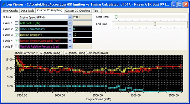
An additional LIVE DATA parameter called ‘Ignition Timing Calculated’ will show what the factory Ignition timing would have been before it was overwritten with RaceROM Ignition Timing, this can be useful to ensure your timing is not excessively different to what the stock values would have been.
Shown below we can see the current Ignition Timing is 10 deg (output of MODE 1-4 Ignition map), this was the actual Ignition timing that was used at this RPM and Load. At the same point we can see the factory timing calculation would have been 8 deg for the same RPM and Load.
Map List
Live Data Parameters
- Ignition Timing (Deg)
- Ignition Timing Calculated (Deg)
- Knock Correction (Deg)
- Knock Sensor Cyl #1 - #6
- Knock Threshold Cyl #1 - #6
Ignition Timing IAT Comp
This map should be used to advance and retard the Ignition timing based on Intake Air Temperature, it should also be used when running a ‘blow through’ MAF setup when IAT measures Charge Air Temp or when Speed Density is enabled.
Knock Sensing
In general, a knock sensor is a device that utilizes a piezo electric cyrstal in order to turn vibrations into an electrical signal. This operates under the same theory as a microphone. Your vehicle's computer then interprets this signal and turns it into a useable value. By looking at the amplitude of the vibrations over the range of common operating frequencies, the system is able to identify changes in engine behavior. When knock occurs it create sa pressure oscillation that transfers into the combustion chamber as vibrations. Pre-Ignition knock and Detonation will present themselves as a higher amplitude vibration at a point in the ignition cycle that coincide with higher cylinder pressure and lowe EGT's. Typically though, pre-igintion will not show up as clearly on the knock sensor due to the timing of the event and speed of the pressure increase occurring.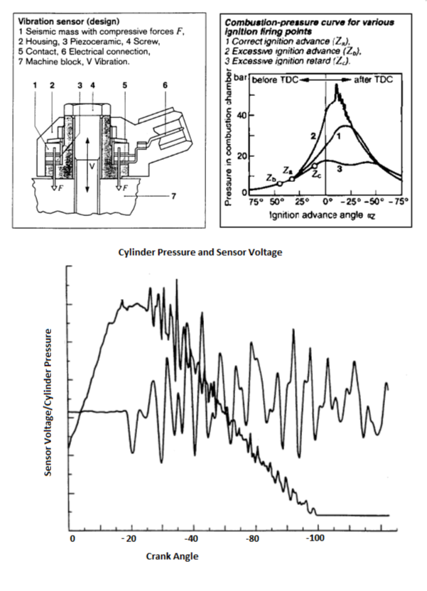
A typical Knock Sensor (Bosch Data Sheets & Automotive Handbook 5th Edition)
Knock Signal Conditioning
The knock sensing system (such as that on a GTR) usually have one or two sensors that are active all the time but only monitored through certain crank angle degrees during a cylinders combustion phase (as in 5-12° ATDC of the ignition cycle to around 40° ATDC). Below is a diagram showing a typical knock sensor signal (green) during a knock and non knock event.
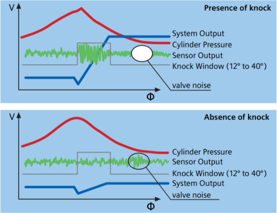
A Typical Knock Sensor Trace (Continental Automive GmbH)
The knock sensor uses a sound wave which is not a signal directly usable by the ECU, the signal requires rectification and integration to be used in the ECU. As shown above the ECU samples the knock count over the knock window (some ECU's may apply band pass filters and amplification) and performs signal conditioning like rectification and integration to give a final value of knock amplitude during the window, the conditioning steps are seen below and the output signal counting up is shown above (blue).
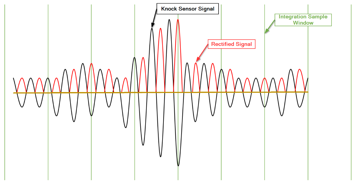 How the GTR interprets Knock Sensor Signal
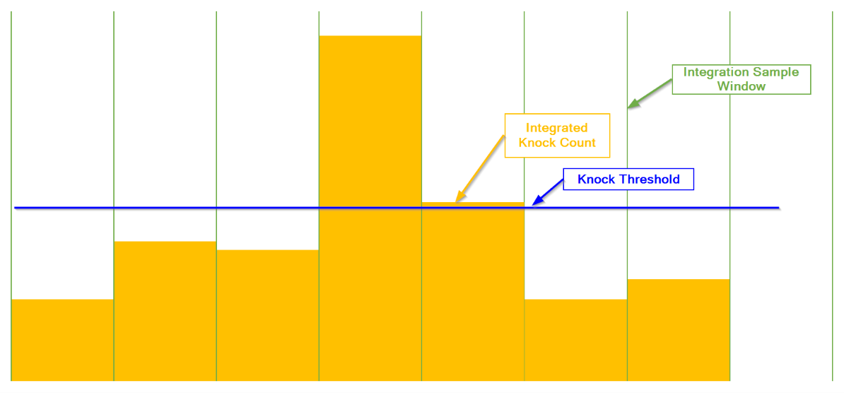
How the GTR Processes Knock Sensor Signals
These knock amplitude (in the case of GTR) is per then stored for each cylinder and compared to a threshold. If the knock count goes above the designated knock threshold and depending on whether the ECU has detected successive knocking events or has a learnt values will then perform some form of ignition retard based on knock, some ECU's will also add fuel in an attempt to cool the cylinders.
As it records the knock events it will continue to retard the ignition, sometimes when successive knock are counted it will add an extra set amount to the retard or multiply by a factor to give a greater ignition retard value allowing and will also add values to learnt ignition. The individual cylinder ignition trim is not automatically altered if knock detection is sensed in only one cylinder, the knock learning is globally applied.
The GTR has flags inside the ROM that allow you to switch of the integration of signal from the Knock sensor at certain frequency ranges. This feature could likely be used to stop knock detection completely or remove certain noisy frequency bands if they exist. These flags may be useful for engines with internal modifications that create more noise in certain frequency bands that are unrelated to knock (forged motors).
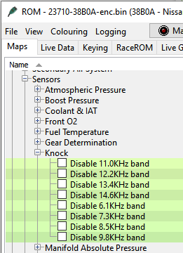
Knock Control Enable
These maps are available for Phase 4 RRFF (version 14389 or newer), they can be used to turn the knock control ON/OFF in each of the different map switch modes and they replace the factory OEM maps shown above.
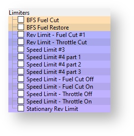
Limiters
Rev Limiter 1
The Engine Speed at which the ECU will cut the Fuel Injectors.
Rev Limiter 2
The Engine Speed at which the ECU will close the throttle.
Speed Limiter Throttle ON/OFF
The Vehicle Speed at which the ECU will close the throttle to maintain a target vehicle speed.
Speed Limiter Fuel Cut ON/OFF
The Vehicle Speed at which the ECU will cut the fuel Injectors to maintain a target vehicle speed. It’s not advised to use the fuel cut method of speed control.
Map List
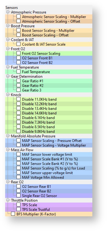
Sensor Scaling
MAF Rescale for Larger Intakes
When fitting larger Intakes the MAF sensor scaling will need to be recalibrated to ensure tight AF correction at light load and full load. These Fuel corrections are called Fuel Trim Short Term (FTST) and Fuel Trim Long Term (FTLT). Accurate FTST/FTLT are needed for accurate AFR tuning but also for correct Torque Output (Nm) for smooth TCM control and avoiding clutch slip.
The standard GTR Intake MAF Tube diameter is 66mm, most aftermarket intakes are 68mm, 72mm the most common is 76mm.
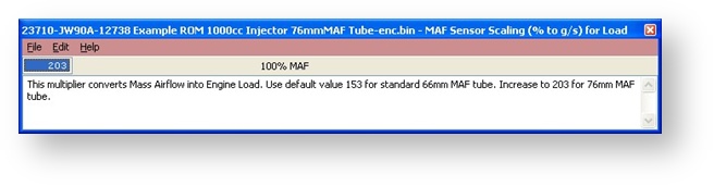
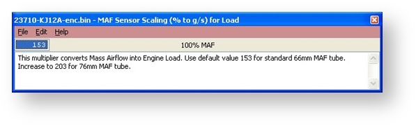
With larger Intakes (like 76mm) you MUST increase the ‘MAF Sensor Scaling (% to g/s) for Load’, this is a coarse adjustment for MAF scaling and this will make 90% of the MAF rescaling that is required, it’s a MAF surface area constant.
The factory default value is 153 for the factory 66mm MAF tube, this should be increased to 203 for 76mm MAF tubes. This is based on the surface area increment amount. The surface area calculation is as follows: Radius squared * PI = Surface area
66mm MAF tubes:
33mm Radius, 33x33=1089mm2, 1089 * 3.14 (Pi) = 3419mm2
69.5mm MAF tubes:
34.9mm Radius, 34.9x34.9=1219mm2, 1219 * 3.14 (Pi) = 3830mm2
76mm MAF tubes:
38mm Radius, 38x38=1444mm2, 1444 * 3.14 (Pi) = 4534mm2
Now if we divide the new 76mm MAF housing surface area by the stock 66mm MAF housing surface area we get the percentage increment amount.
4534/3419 = 1.326 or if you prefer ‘the 76mm MAF tubes have a 32% greater surface area’.
So if we simply multiply the 1d map called ‘MAF Sensor Scaling (% to g/s) for Load’ by 32%
153 * 1.326 = 203. If the MAF tubes are 69.5mm (2.75 inch) then enter 171
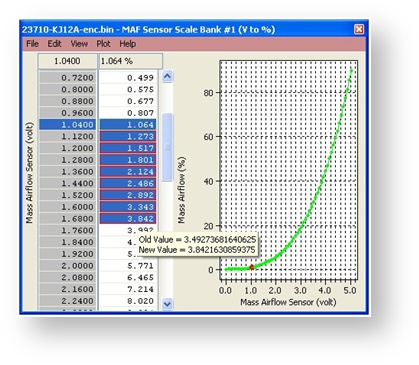
With the MAF Tube now calibrated to the larger Intake size you can now make the Fine MAF tuning with the 2d MAF Scale for the corresponding bank (Bank #1 or Bank #2). Start the car and make a log at Idle, Fast Idle, Light Load and Full Load watching carefully the AFR and Knock Correction. Be sure to including the following parameters in your log file:
- Fuel Trim Short Term B1/B2
- Fuel Trim Long Term B1/B2
- AFR B1/B2
- MAF Volts B1/B2
- Mass Airflow (g/s) B1/B2
If the Fuel Trim Short Term (FTST) values are at 120% then the ECU is increasing the Injector Open Time ms by +20% to achieve your Target AFR from the Fuel map, if the FTST is 85% then the ECU is reducing Inj ms by -15% to make the target AFR. So for a reasonable FT error (over 110% or under 90%) the 2d Maf Scale (g/s) should be adjusted at this point by 50% of the FT correction value.
Let’s say we see Fuel Trim is about 120% between 1.04v and 1.7v MAF Volts. We simply increase MAF Sensor Scale #1 by +10% on the 2d MAF Scale for Bank #1 therefore reducing the STFT at this point. The same sequence should also be followed for Bank #2 and all adjustments should be smoothed into the local values.
MAF Rescale for Larger Intakes using SD
Another option is to rescale MAFs using Speed Density. This is very simple and provides verification that our MAF scaling is correct.
The screenshot below shows two log files created from a car running on SD.
76mm Intakes fitted running on SD
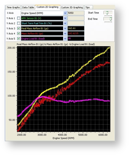
Stock 66mm Intakes fitted running on SD
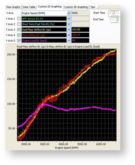
You can see the second log shows a stock 66mm MAF tube and the Mass Airflow reading from SD (Yellow line) and MAF Mass Airflow (Red line) are very close. After fitting the new 76mm Intakes you can see the top log file shows the MAF Mass Airflow B1 (Red line) reading has dropped but the SD Mass Airflow (Yellow line) is still accurate and the car runs fine as its running on SD. Now we can leave the car on SD and simply increase the MAF scaling until the MAF Mass Airflow (Red line) reaches the SD Mass Airflow (Yellow line). See the previous noteson MAF rescaling for further info on the rescaling technique. Once the MAF Mass Airflow is the same as the SD Mass Airflow then we can turn off SD as we have a perfectly scaled MAF curve!
MAF Sensor Scaling (% to g/s) for Load
When fitting larger MAF housings (or Induction kits) then this value should be increased proportionally relative to the surface area increase of the larger MAF housing, This is a coarse adjustment for MAF scaling, it converts the MAF sensor % value into grams of air per second.
MAF Sensor Scaling Bank 1 / 2
These maps should be used to fine tune the MAF sensor scaling after the MAF Sensor Scaling map has been calibrated. When fitting larger Intakes it is critical that the MAF scaling on both banks are corrected. This MAF scaling process can really be helped by utilising the Speed Density function in RaceROM. See the Hints and Tips section later for MAF Rescaling advice.
BFS Multiplier (K-Factor)
Adjusting this value will rescale the engine load and it is not recommended to change this value.
This value was named as MAF SIZE in older software but through phase 3 development it should NOT be used as it drastically affects many maps and many load and torque calculations that cause poor drivability in general.
Important: Always ensure the K-Factor is set to factory value of 26806 like shown below.
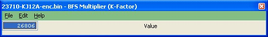
The RaceROM updates beyond phase 3 release version allow Engine Load values in excess of 300% for the fuel and timing maps, so rescaling should only be necessary on very high horsepower vehicles.
Map Sensor Scaling
This is the sensor located in the Inlet manifold, which is used for Driver Display Boost Gauge reading and is also used by RaceROM Speed Density. The standard sensor is a 2.80bar Absolute sensor. See the Hints and Tips section for more info on rescaling.
Boost Sensor Scaling
The Boost Sensor Scaling Multiplier and Offset maps are the two sensors fitted pre throttle and are used for boost control. The standard sensors are 2.80bar Absolute.
Atmospheric Sensor Scaling
There is no need to adjust this sensor scaling map.
Coolant and Intake Air Temp Scale
This map can be used to rescale the Coolant and Intake Air Temp sensor voltage to temperature scaling.
Engine Cold/Warm Thresholds
The coolant temp thresholds that the ECU will swap between certain Cold and Warm maps like Ignition and VVT maps.
Map List
Live Data Parameters
Torque
The GTR Engine Control Module (ECM) and Transmission Control Module (TCM) depend completely on Torque calculations.
It is critical that the Torque value output from the ECM is accurately calibrated, if it is not then pulling away, gear shifting and gear selection will range from being unresponsive, hesitant and uncontrolled to dangerously aggressive and unbearably hard and this could drastically shorten the life of the transmission.
Calibrating the Torque values is not normally needed when using EcuTek RaceROM version 3 or newer, these later RRFF have superior high load rescaling and high resolution Torque map definitions which provide very smooth and detailed interpolation, they are calibrated to 1000Nm.
When used in conjunction with the latest LC5 TCM ROM (KJ or 38B series TCM ROMs) then the driveability will be better than any stock GTR and will be silky smooth.
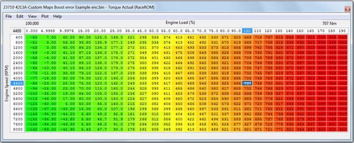
How to calibrate the Torque Actual map
The Torque Actual map contains the Torque figure that is given to the TCM for a given Engine Speed and Engine Load. This Torque value in Nm is then given to the TCM and various other modules on the vehicle. There is also a Torque Demand Multiplier map that will increase the torque value for a certain gear (or Gear Ratio)
To start, calibrate your fuel trims until they are between 90 to 110%, if you can fine tune them to be as tight as 95 to 105% then even better, this needs to be done at Idle, under cruise conditions and then full load all the way to the rev limiter.
Assuming the Fuel Injector scaling is correct then you need to adjust the MAF scaling (or the SD VE map if you are running on SD) until the fuel trims are as close as you can get to 100%. By adjusting the MAF scaling or SD VE map you also correct your Engine Load (X axis of the Torque Actual map) and therefore the output of the Torque Actual map.
Understanding the Torque map
To understand the effect of the Torque Actual map we need to exaggerate the changes for the purpose of example.
- If you drastically reduce the Torque map values then the Torque value reported to the TCM will be lower and the clutches will slip when pulling away, on gear changes and also full time slip on full load, the clutch life will be counted in seconds if this happens.
- If you drastically increase the Torque map values then the Torque value reported to the TCM will be higher and the clutches will be engaged at Idle and the vehicle will creep in traffic and also the gearchange will be very firm.
If using RaceROM version 3 or newer there is no reason to adjust this map.
If you have replaced the clutch packs with uprated clutch packs then you may need to reduce these values at lower Engine Loads for improved drivability (below 100% Engine Load). But try adjusting the Clutch Touch Points and Clutch Capacity before adjusting the Torque Actual map,
Increasing the Torque values in the Torque Actual map will NOT make more power, it will only impact (and likely upset) the drivability of the vehicle!
The torque value is sent over the CAN bus to the TCM, where it is used to calculate clutch clamping pressures, as above if the torque value is too low then the clutches will slip.
Make a log file of the TCM (using the TCM ROM) then you will see the following:
- Clutch A will be used for gears 2, 4 and 6
- Clutch B will be used for gears 1, 3 and 5
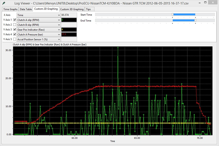
You can see that this log file below shows that in 4th Gear the clutch slip is between 0 and 15rpm, this is pretty normal. Additionally Clutch A Pressure is flat lined at 17.1bar, this is slightly higher than normal as most clutch pressures will be around 16.5bar. If you feel the clutches are slipping on full load while you could add 20% to the Torque Actual map over 80% Engine Load, the easier (and preferred) method is to increase the Clutch Capacity to +8 and make another power run and log of the TCM, see if the clutch slip reduces. With that letting you know the impact of the changes you would then increase the values in the Torque Actual map.
Map List
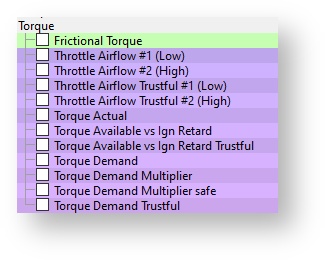
Live Data Parameters
- Torque Actual (Nm)
- Torque Demand (Nm)
EcuTek ProECU tuning tools tools should only be used by experienced tuners who understand the product and engine calibration.
If you do not fully understand this product then you WILL damage your engine, ECU or your vehicle.
Please ensure you fully read all EcuTek manuals BEFORE attempting to use ProECU with your laptop or your vehicle.
Use with extreme caution and understanding at all times, if in doubt then do not proceed.
EcuTek accepts no responsibility for any damage to the engine, ECU or any part of the vehicle that results directly or indirectly from using the product.
** If you are in any doubt that you do NOT have the experienced required to use this product then you should NOT USE IT **
Retail customers
** If you have any doubt that you do NOT have the experienced required to use this product then you should NOT USE IT, you should simply contact your EcuTek Master Tuner shown clearly on the top of your Programming Kit or visit your preferred tuning shop to have a professional tuner to use it for you **