BMW F-Series N55 & S55 Tuning Guide
- Brandyn Mowat
- Paul Blamire
- Chris Todd
BMW F Series ProECU Tuning Guide for N55 and S55
Introduction
The ProECU for BMW F-Series products cover N55 and S55 platforms across a range of models. Providing an all-in-one tuning solution that enables a tuner to properly calibrate cars of all hardware levels.
RaceROM custom code by EcuTek adds functionality unique in the tuning marketplace such as CANbus sensor input, Flexfuel and Custom Maps for general purpose use.
The strategies in the BMW F-Series ECU are many and complex, fortunately tuning can begin at a very basic level by simply increase the requested torque and lifting some safety limits. As hardware upgrades become more thorough and power requirements increase, more in-depth calibration is required.
maps denoted with a RaceRom logo ![]() are tables from the RaceRom software and require the addition of that software.
are tables from the RaceRom software and require the addition of that software.
Engine Variants
- Used in 135i, 235i, 335i, 435i, and misc X3, X5 and 6 series models
- 302ps power output
- 400Nm torque output
- 6600 Max nominal engine speed
- Single turbo with either electronic or pneumatic wastegate actuator
- Open deck block cast around iron cylinder liners
- Cast Iron Crankshaft
- Used in M135i, M235i and M2 models
- 322ps or 355ps power outputs
- 450Nm or 465Nm torque outputs
- 6600RPM Max nominal engine speed
- Single turbo with electronic wastegate actuator
- Open deck block cast around iron cylinder liners
- Steel Crankshaft
- Used in M2 Competition, M3 and M4 models
- 426ps to 493ps power outputs
- 480Nm to 600Nm torque outputs
- 7600RPM Max nominal engine speed
- Twin turbos with electronic wastegate actuators
- Twin high pressure fuel pumps
- Water cooled intake air charge cooler
- Closed deck block with coated aluminium cylinder liners
- Lightweight steel crankshaft
- High Flow optimised oil pump with low temperature thermostat
- 6cyl 3.0 Engine
- Bosch HDP5 High Pressure Fuel system
- HDEV5.2 High Pressure fuel injectors
- Bosch CVO Controlled Valve Output system
- Variable position inlet and exhaust camshaft
- Infinitely variable lift inlet cam (used instead of throttle to control airflow at low load)
Tuning Workflow
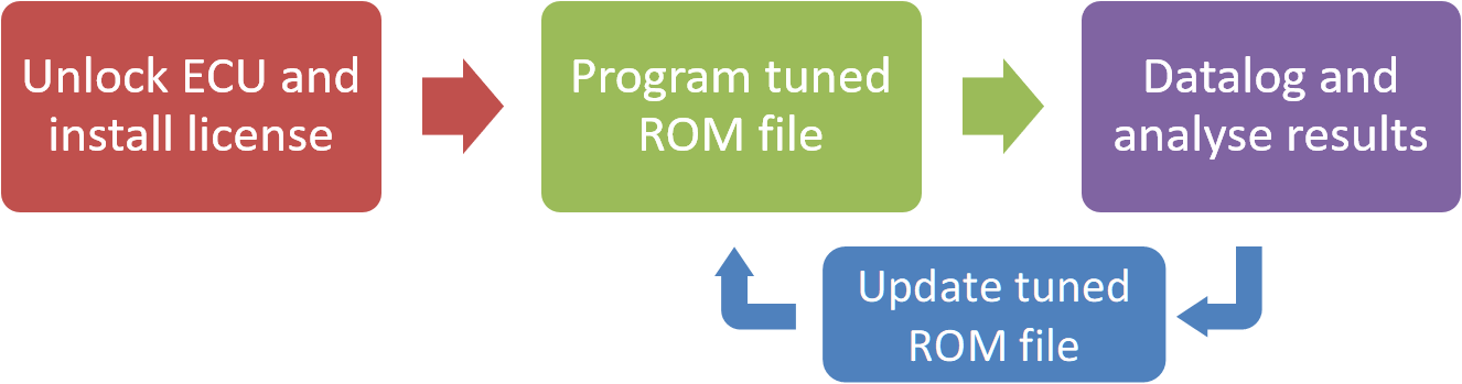
Unlike other EcuTek tuning solutions, a two-step process is required to begin tuning.
The first step is to unlock the ECU, the EcuTek licence is also installed during this process, but it only needs to be done once, using a green EcuTek CAN cable this can take around 8 minutes. Once unlocked, tuning is the same as most EcuTek platforms and a tuned ROM can be programmed this takes about 2m30s but can be around 90s if changes are limited.
Datalogging the tuned ROM to check key parameters can then be carried out. Depending on the nature of the tuning the tuned ROM can be updated and retested until the tuner is happy with the results contained with the logs.
The BMW specific unlock and programming process is covered here:
Torque
The requested torque is eventually converted to the a load request, and beyond the basics of limiting load separately from torque, some cars need more in-depth calibration to avoid being limited.
We start with the Torque Desired Max:

Then that gets scaled by driver demand in percent:

Which gives us a driver demanded torque at the clutch:

The ECU adds the external losses for say PS pump, and alternator load to give an "Engine Torque" but this will be at the current operating conditions, then the ECU converts that to "Indicated Torque" which will be the torque at reference ignition which is often MBT. We will almost certainly be running at less than MBT and in simplified terms if you target 800Nm at the clutch at 10deg below MBT, your equivalent torque if you were at MBT with everything else the same would be say 890Nm. There are usually maps to calibration for how much torque is lost for a given retard from MBT, and then that is weighted by a factor often known as ignition efficiency. We also need to add frictional torque in to this,
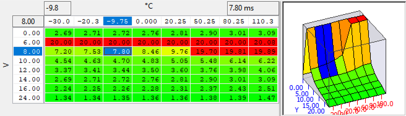
Our Friction losses map looks like this, negative numbers signifying the friction reduces the torque output

The Ignition to torque percentage looks like this: with retard from MBT on the Y axis

So to get from clutch torque to the torque number used in the Torque Actual maps, we have something like:
(Clutch Torque + Ancillaries Losses + Frictional Losses) / ( Torque correction for MBT Offset * Ignition Efficiency) = Reference Torque
eg (using guestimate numbers for friction and ignition efficiency)
(808 + 3 + 63) / 0.92 = 950Nm
In our case, that number gets fed into the Torque Actual map to generate a load figure. In our case we can see that by the time the corrections for friction and ignition are fed in, we are already on the bottom line of those torque actual maps. I can also see that based on your numbers, the car appears to be using Torque Actual 2.

This is why with your large torque demand you're still running the max row of that Torque actual map, and why adding more torque demand isn't going to increase your boost. We can see the torque value fed into this map on the log with "Torque Desired for Desired Load" (there will be some minor corrections here and there but in general the numers will match within 2-3%)

We can see the output of this torque actual map in terms of load on the log:

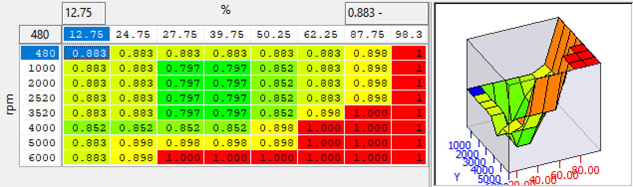
So by now we can see why the Torque actual maps need headroom, especially in terms of load to be able to generate the demand for airflow and ultimately boost. But we're still dealing in the realm of load, or cylinder fill, and that needs to get converted to a pressure in order to drive the boost control. This is where things can get a bit sketchy, as the ECU is going to use it's VE model to calculated back to a required manifold pressure level, but it will also factor things in like the exhaust manifold back pressure (which includes the exhaust system pressure loss) and then the residual gas pressure ratio (basically how much fresh cylinder charge will be displaced by exhaust gas from the last cycle).
And we can see that even though the cylinder fill demand was pretty flat at 240%, the boost target was not, a low boost target is a reflection of the ECU calculating a higher VE.
In the log we can see the low boost demand below 4000rpm, or alternatively a high boost demand above 4000rpm.

This is where the original model and calibration can be lacking, whether that's due to headroom in calculations or maps used in then, or a result of a non ideal learning for airflow, As a result the "Max Load Factor" can be important, as it can be used to limit the VE result that might be artificially high as a result of blowthrough where intake air is effectively lost to the exhaust in regions of high cam overlap.
Not putting very high values in this map can help I believe, and I have tend to go back to more of a stock looking map, which is something I would try to encourage the boost up in the low RPM zone.

Similarly there is this map which is used to cap the calculated cylinder fill used when looking up an actual torque value, having very high values in this may mean that blowthrough again causes an issue but with a high torque actual value, which may cause the throttle to partial close on some calibrations as the ECU tries to keep the load on target.

One nice option rather than changing the max target pressure ratio is to use a custom map to adjust your maximum target boost by RPM though it's a good idea to also adjust target torque and cylinder fill desired.

It's worth remembering that Turbo Pressure Raito is compressor outlet pressure/compressor inlet pressure, and if you start to deal with altitude that may not give you the results you want to protect the engine, as it's mainly a tool for protecting the turbo. The custom map I've outlined will cap the absolute boost at all altitudes and allow you to run a PR ov over 2.6 to maintain the high boost at high altitude (if that's what you want).
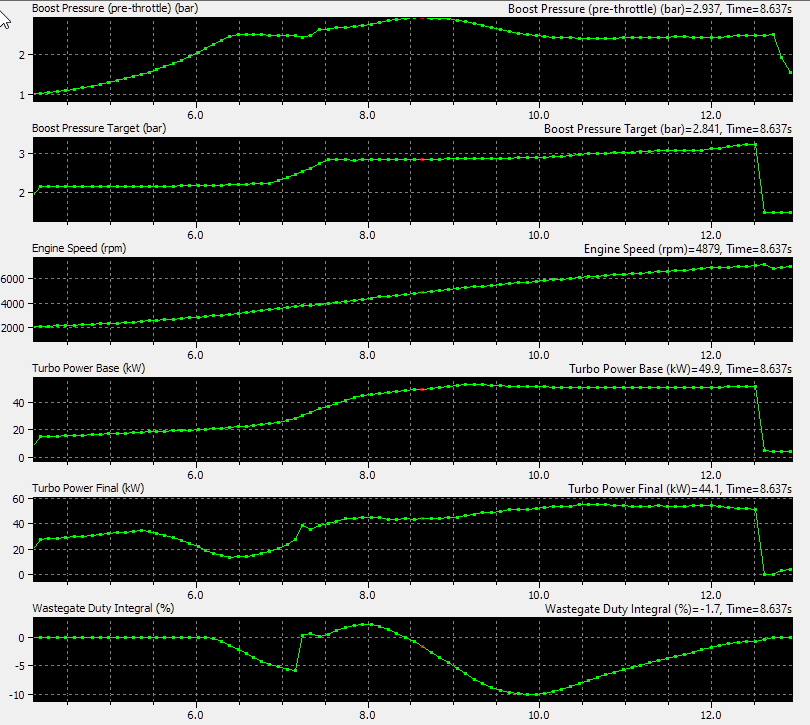
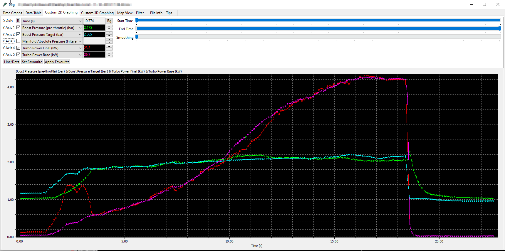
We can see here that the base turbo compressor power is just too high, the adjust value after the PID loop that controls the turbo power requirement was already 5kw below the base number, and then the WG duty PID loop, which operates in addition to the turbo compressor power control, was pulling further duty out.
Ignition Coil Dwell Timing
The BMW F-Series uses base ignition coil dwell maps in conjunction with load and RPM compensation. BMW may also implement a multi-spark coil trigger strategy for better combustion.
When the ignition angle is fixed for a cylinder the dwell time is calculated the correct trigger timings set by low level ECU architecture. The two maps used during single spark mode are the Coil Dwell Time base and the Coil Dwell time Multiplier, the base value is a setpoint for Battery voltage and coolant temperature while the multiplier is engine speed and load based. the calculation for final time is as simple as follows,
Dwell Time = Coil Dwell Time Base X Coil Dwell Time Multiplier
Dwell Time Base
Dwell TIme Multiplier
Boost Control
For the most part, boost control is adjusted in response to the torque demand, as torque demand increases, the computer will modulate the boost level requested to match the torque level needed. In this form, while it's complex in the way it's implemented, it has the ability to be relatively easy to tune.
Target pressures for the inlet manifold and resulting boost are more difficult to control beyond what the ECU calculates as being appropriate, but with careful tuning it's possible to achieve almost anything. The boost target begins with Torque request, which is used to calculate the correct pressure to achieve the desired torque in the current conditions.
Wastegate actuator control is achieved with a system using two control methods, one based on the turbo shaft power, and another that makes further corrections to the target wastegate position. It's reasonable to tune both systems to keep the boost on the target.
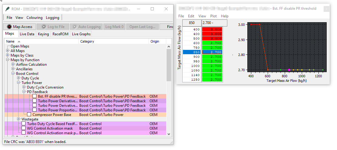
Bst. FF Disable PR Threshold
This map functions as a threshold for switching between two different boost control methods. When the PR (Power Rate) is below the value in the map, the Turbo Power Model based control is used. When it's above this map it utilises direct wastegate duty based control.
This is typically the first map you'll want to tweak, we suggest values similar to what we have used in the M2 ROM pictured.
In the log shown below we cover an overboost and underboost condition.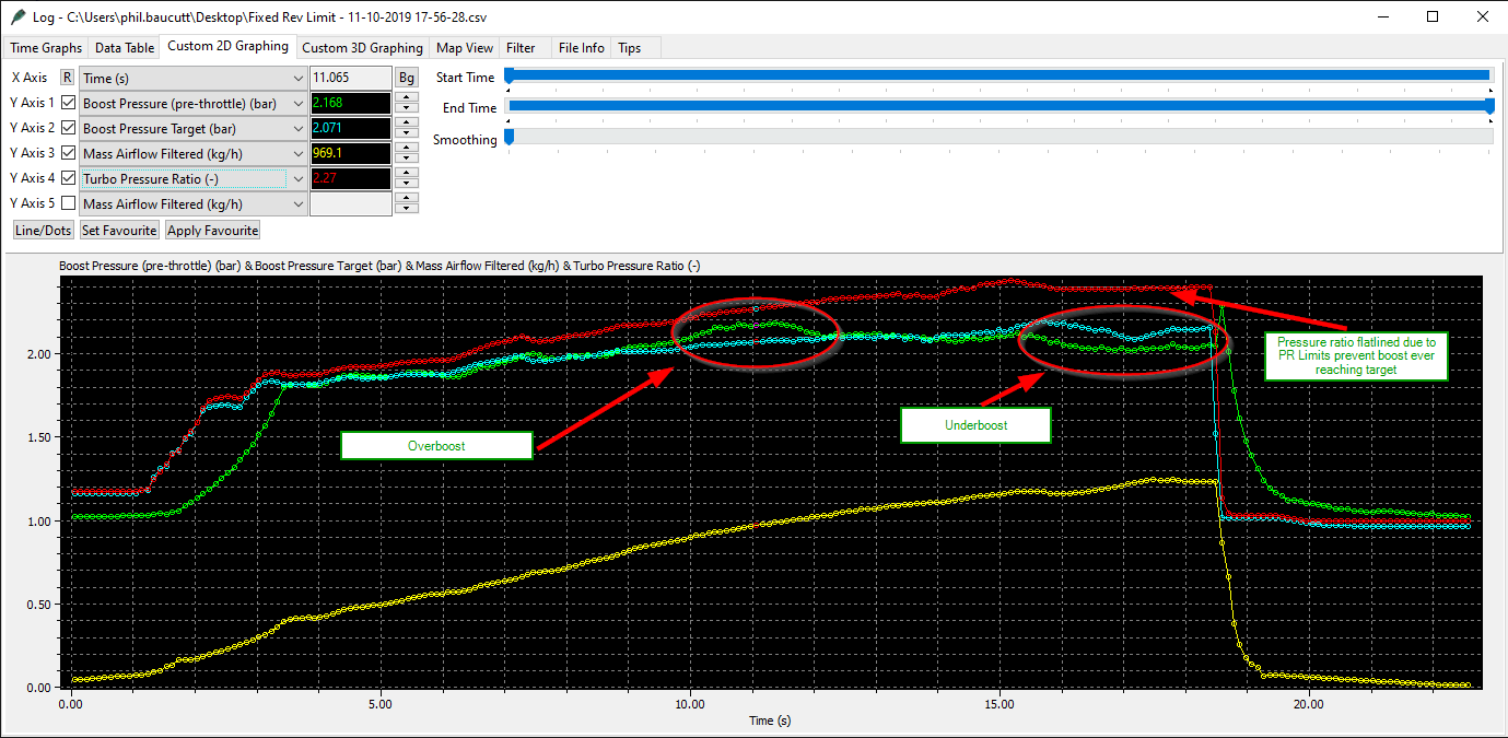
In this particular case, the underboost is being caused because the Turbo PR limits are capping the boost target. It's quite easy to spot when comparing the Boost Target against Actual Boost +Boost Error (As demonstrated by the "Boost Target Real" parameter shown below.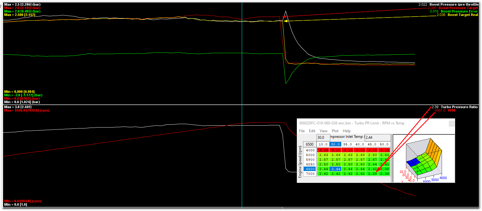
Looking at the same overboost example before, we can see there's quite a large amount of overboost.
The overboosting begins around 850 kg/h Mass Air Flow and ends just short of 1050kg/h at 2.1 to 2.3 Turbo Pressure Ratio.
With that information in hand, we'll take a look at the Compressor Power Base cells controlling behavior at those points.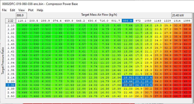
To give us an idea of the rough corrections needed, we can reference the log file again and compre the Turbo Power Final and Turbo Power Base
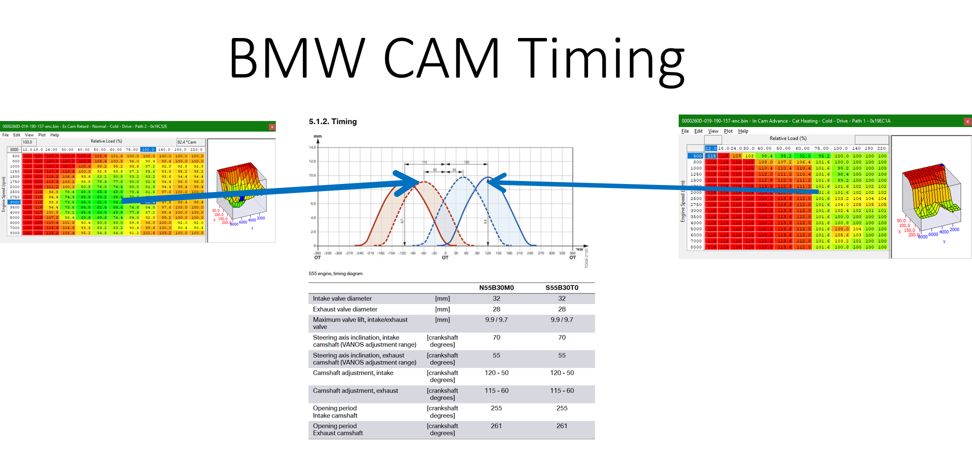
Camshaft Timing
Fueling
The F-Series fuel system is based around the Bosch HDP5 range of components comprising of:
- Low Pressure in tank pump with closed loop pressure control
- High Pressure pump with dedicated drive cam
- High pressure HDEV5.2 Injectors with CVO adaption.
It's possible to upgrade elements of the system, and many N55 cars will require at least an upgrade high pressure pump to take full advantage of even the stock hardware.
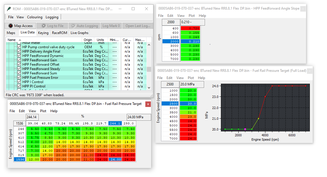
Typically the stock fuel pressure maps are only calibrated to deliver 20MPa. While you can change fuel target even a bump to 26-27MPa results in only around 23MPa. In addition it ends up slowly ramping up to that target if you only rely on the closed loop control in order to achieve your desired fuel pressure target.
The right way to raise your fuel pressure is to start off by adjusting the fuel pressure targets, then the HPP Feedforward Angle Offset & HPP Feedforward Angle Slope maps in order to correctly deliver the target.
Related Topics
EcuTek ProECU tuning tools tools should only be used by experienced tuners who understand the product and engine calibration.
If you do not fully understand this product then you WILL damage your engine, ECU or your vehicle.
Please ensure you fully read all EcuTek manuals BEFORE attempting to use ProECU with your laptop or your vehicle.
Use with extreme caution and understanding at all times, if in doubt then do not proceed.
EcuTek accepts no responsibility for any damage to the engine, ECU or any part of the vehicle that results directly or indirectly from using the product.
** If you are in any doubt that you do NOT have the experience required to use this product then you should NOT USE IT **
Retail customers
** If you have any doubt that you do NOT have the experience required to use this product then you should NOT USE IT, you should simply contact your EcuTek Master Tuner shown clearly on the top of your Programming Kit or visit your preferred tuning shop to have a professional tuner use it for you **