Per Gear Maximums
| Note |
|---|
These tables are still affected by load and torque limits, as such those will need to be modified if targeting values higher than those limits. |
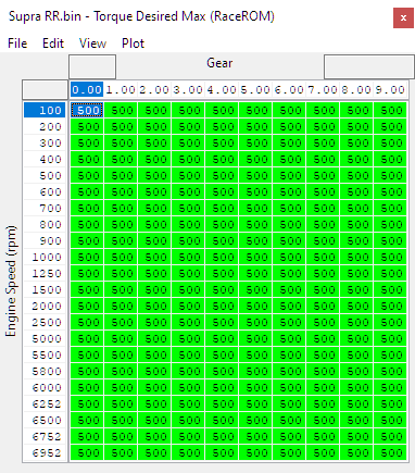
Torque Desired Max (RaceROM)
This table allows you to set a desired max amount of torque per gear by RPM. This torque request is scaled but the output of the driver demand maps such as Torque - Driver→Pedal Request - Drive AT and related maps.
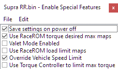
Only used when "Use RaceROM torque desired max maps" is enabled in RaceROM Special Features→Enable Special Features and overwrites the values from the map Torque - Engine→Clutch Torque Maximum (which can be left stock if the RaceROM map is enabled and calibrated).
If Flexfuel is also enabled, it's blended with RaceROM FlexFuel->Torque→FlexFuel Torque Desired Max
Torque Desired Max Scalar by MS Mode (RaceROM)
Allows a percentage multiplier to be applied to the Torque Desired Max (RaceROM) table based on map slot. This can be handy to allow map modes of varying power levels for use with different drivers / driving conditions. These can be customised further to allow for different percentage changes for normal vs sport mode.
Map modes are in a descending order with the top of each section being slot 1.
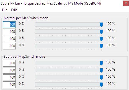
The final output of the RaceROM Torque Desired Max be logged using the Torque Desired Max logging parameter.
Torque Request Multiplier
Since the factory torque requests from the pedal are percentage based, as you increase the amount of torque being targeted either through the RaceROM maps, Flex Fuel (or even the stock maps) you can run into some undesireable behavior. At low throttle positions you'll still be requesting the same percentage of torque, but because your targets are higher, you'll be targeting more torque than you'll really want to see at those lower pedal positions or gears.
For example, if you're targeting 20% more torque than stock, than you'll also be targeting 20% more torque than stock at 2% throttle.
This table provides a function allowing you to set a multiplier curve to adjust the sensitivity of the accelerator pedal per map slot to target a lower level of torque than it would otherwise be trying to reach. This works in conjunction with the factory Torque-Driver → Pedal Request maps.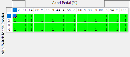
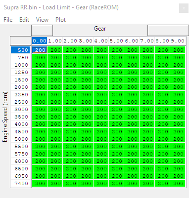
Load Limit - Gear (RaceROM)
This table allows you to set different load limits by RPM per gear, they are used in conjunction with the OEM load limits. The lowest value from any of the active limits will set the final limit on the target load.
Load Limit Scalar by MS (map slot) Mode
This map sets a percentage multiplier to the Load Limit -Gear (RaceROM) value by map slot. This can be handy to have map modes of varying power levels for use with different drivers / driving conditions. These can be customised further to allow for different percentage changes for normal vs sport mode.
Map modes are in a descending order with the top of each section being slot 1.

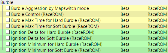
Burble Control
The burble control allows the tuner to configure maps for soft and hard burble. The ECU will interpolate between these maps based on the Burble Aggression parameter which can be configured independently for each mapswitch mode and also through custom maps if you want to control it from a cell phone. For further information check out our guide below.
Ignition Base Timing Maps & Lambda / Fuel Maps
Map switching allows you to switch between multiple versions of the Ignition and fuel maps allowing for different driving behavior in different maps. Keep in mind that these tables may come before other compensations. If you see it running at a different value than you expect, make sure your other limits and safeties aren't coming in to play.
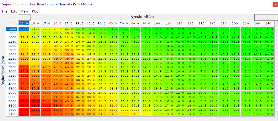
Ignition Base Normal/Safe Timing Mode 1-4
Uses Cylinder Fill % (x-axis) and engine speed in RPM (y-axis) to set base ignition timing in normal mode and safe mode. Replaces the factory Ignition Base Timing Offset Multiplier map. Once the RaceROM maps are activated the base map will no longer operate.
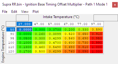
Ignition Base Timing Offset Multiplier
Applies a multiplier to the Ignition Base Timing maps using Engine Temperature (Coolant) and Intake Temperature to modify the timing for varying environmental conditions.
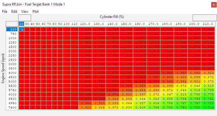
Fuel Target Bank 1 Mode 1-4
Sets the fuel target for bank the engine using Cylinder Fill % (x-axis) and engine speed in RPM (y-axis). Replaces the factory Fuel Target Bank 1 map. Once the RaceROM maps are activated the base map will no longer operate.
These tables have additional resolution (rows and columns) when compared to the factory map. As such you may need to interpolate some of the cells from your factory map if it was tuned previously, rather than simply copy and pasting it in.
Valet Mode
Selecting Valet Mode
Enabling Valet Mode in the software can be done easily by navigating to the Enable Special Features Map and toggling the Valet Mode option.
How to Use Valet Mode
Press the cruise control UP button until the rev counter reads 7
Temperature gauge will show 6 bars for valet mode OFF, or 7 bars for valet mode ON.
Press the RES/CNCL button to select ON or OFF as desired.
Note When valet mode is enabled, the torque and max speed of the vehicle is limited according to the distance travelled.It can be used to prevent misuse of the vehicle or as an additional anti-theft measure to complement the inbuilt security.
| Note |
|---|
There are two different steering wheel options. Make sure you're pressing the correct button. |
Vehicle Speed Limit Override
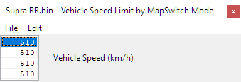
RaceROM has its own vehicle speed limit maps which override the limit set in the vehicle coding. These can be set per map-Switch Mode

Saving Selections at Key Cycle
Depending on the circumstances, you may or may not want your mode selections to persist after a key cycle. The mapswitch mode, torque/power settings, custom inputs (from ECUconnect app) and valet mode settings can be backed up into the EEPROM when the ignition is turned off, and restored when you start up again.
ECU Connect APP Integration
Using the ECU Connect you're able to manipulate things like burbles, map slots, or even change values within custom maps. For a guide on how to do this check out our guide
RaceROM Custom Input
The Custom CAN input feature in RaceROM allows you to import CAN data from an external sensor such as a wideband or ethanol content analyser.
Installation
The BMW ECU has three CAN channels (PT-CAN, PT-CAN2 and K-CAN5), none of them are directly connected to the OBD port. You cannot connect the CAN sensor to the OBD port. You must connect the CAN sensor directly to one of these buses. Suggested connection points are near the ECU in the engine bay or the Front Electronic Module in the passenger footwell.
The pins you'll want to utilise for this system can be found on Connector A46*1B as shown in the diagram below.
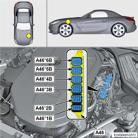
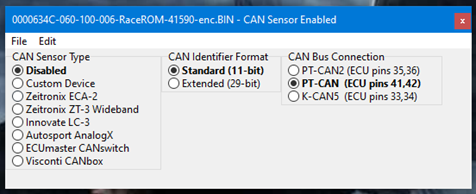
- PT-CAN bus is ECU connector A46*1B pins 41 & 42.
- PT-CAN2 bus is ECU connector A46*1B pins 35 & 36.
- K-CAN5 bus is ECU connector A46*1B pins 33 & 34.
CAN Sensor Configuration
In the CAN Sensor Enabled map you'll be able to select your CAN sensor type from a list of pre-configured items, or custom devices. Note that the presets only apply if you're using the standard CAN ID of the unit.
| Note |
|---|
If you set your CAN device to use a custom CAN ID you'll need to input the value manually. |
RaceROM Custom CAN Output
This feature allows you to configure the ECU to output a custom packet onto one of its CAN buses. This packet can be used to pass data over the CAN bus from the ECU to another module such as a custom display or water/meth injection controller. In future we plan to include pre-calibrated profiles for a selection of supported devices, but currently there are just two options, "Custom Device" that you can configure yourself, and "EcuTek Test Packet" that will output a packet containing "EcuTek" followed by a sequence number and a checksum.
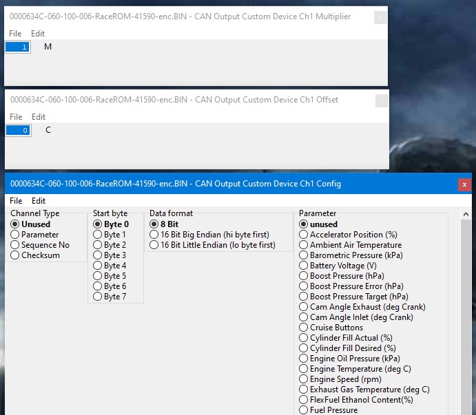
With control of up to 8 parameters (channels) to be included in the packet. You can scale each channel to ensure that its expected range of values fits into 8 bits (0-255) or 16 bits (0-65535).
A channel can contain either a constant value, a parameter, a sequence number (heartbeat), or a CRC8 checksum of the other bytes in the packet.
For each channel, you specify the start byte within the packet, and the format, 8 or 16 bits (big or little endian). The total number of bytes you can output in the packet is 8. Most CAN packets send the full eight bytes, even if some of them are not used, but you can send a shorter packet if you need to.
For example, you could configure channel 1 and 2 to output 16 bit values, starting at byte 1 and 3 respectively, then channels 3, 4 and 5 as 8 bit values starting at bytes 5,6 and 7. Then channel 6 as a checksum at byte 8. Channels 7 and 8 would remain unused.
To send a constant value, select parameter, then set the parameter type as unused, then specify the constant in the offset map for that channel. The sequence number will increment for every packet from 00 to FF and then rolls over to 00 and counts up again.
| Info | ||||
|---|---|---|---|---|
| ||||
|

| Warning |
|---|
For additional information on Ethanol Content Sensor setup and failsafes, check out the RaceROM Flex Fuel section |
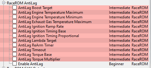
RaceROM Antilag
The Antilag feature is designed for roll racing. It is similar to the Rolling Launch feature in our GTR product. The objective is to spin up the turbo and create a reserve of boost in anticipation of rapid acceleration.
To Use
- Ensure the cruise control system is deactivated.
- While driving forward press and hold the cruise control "Set" button, you can adjust the speed by modulating the accelerator. Increased input will demand slightly higher torque and allow subtle acceleration and vice-versa.
- When the driver wishes to launch simply release the cruise "Set" button.
While activated, the Antilag feature selects a boost target (default 1800hpa) and applies closed-loop ignition retard to generate more exhaust gas energy and help maintain that target.
Best results can be achieved by manually selecting a suitable gear prior to activating the feature, if used in auto, the accelerator pedal input will cause a downshift.
| View file | ||||
|---|---|---|---|---|
|
| Note |
|---|
There are two different steering wheel options. Make sure you're pressing the correct button. |
Enable AntiLag
Switch that activates AntiLag system per map slot mode. Also provides the option to force the Exhaust Flap open to increase flow on map slots where you're using the AntiLag system.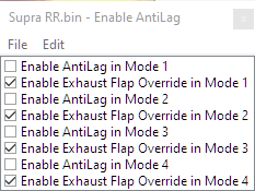
AntiLag Boost Target
Establishes a boost the ECU will attempt to achieve while the anti-lag system is active. The four settings are for the 4 map switching modes.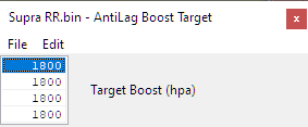
AntiLag Engine Temperature Maximum
Sets a Maximum (high) temperature the engine coolant temperature must be below in order for the AntiLag system to engage. Since this system can cause an increase in coolant temperature it's a good idea to keep this at a reasonable level to prevent overheating or engine damage.
AntiLag Engine Temperature Minimum
Sets a minimum (low) temperature the engine coolant temperature must be above in order for the AntiLag system to engage. Keeping this to a sane value ensures that the car is up to proper operating temperature before using engaging the system.
AntiLag Exhaust Gas Temperature Maximum
Sets a Maximum (high) temperature the exhaust gas temperature must be below in order for the AntiLag system to engage. Because this system can cause an increase in temperature as a result of using the AntiLag feature it's important to keep the exhaust gas temperature to a safe temperature to avoid damage to engine components.
AntiLag Ignition Ramp Rate
Establishes the rate in degrees of ignition timing the system will alter ignition timing over a period of time.
AntiLag Timing Base
Base values the system will use to alter ignition timing when the system is activated. These are adjusted over time by the ramp rate and the AntiLag Ignition TIming Proportional in order to hit the desired boost level.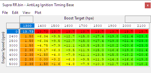
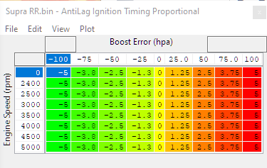
AntiLag Ignition Timing Proportional
The change to existing ignition timing after the AntiLag Timing Base values are applied that the system will utilise in order to correct for boost error (failure to meet or maintain the AntiLag Boost Target)
AntiLag Lambda Target
The fuel target the AntiLag system will use while the AntiLag system is active.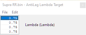
AntiLag ReArm Timer
In order to prevent heat buildup or damage we recommend not using the AntiLag system continuously without allowing the engine to properly cool down in between. This value sets an amount of time that must pass before the system can be activated again.
This either begins after AntiLag was just used, or if the system shut it down due to the AntiLag Timeout value being exceeded.
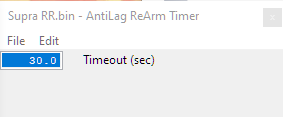
AntiLag Timeout
Amount of time the AntiLag system can be active before shutting down. An important value as the system generates a lot of heat in the turbocharger and exhaust which can be damaging.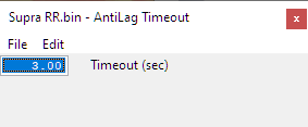
AntiLag Torque Base
Adjustment to the torque request based on gear. Important to maintain speed as higher gears will require more torque in order to keep the same amount of speed.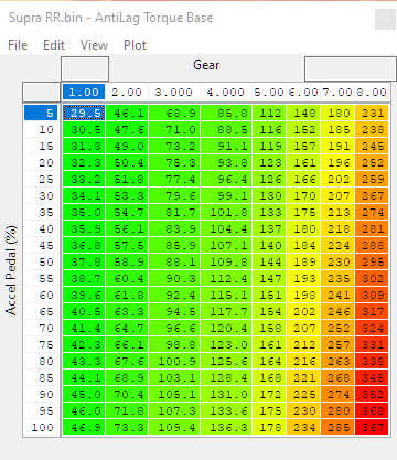
AntiLag Torque Multiplier
Works in conjunction with the AntiLag Torque Base table. Applies a multiplier to that value to adjust for the added torque required at higher vehicle speeds to maintain speed when the system is active.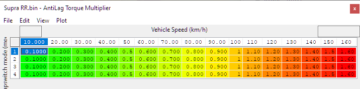
FlexFuel Ethanol Fixed Values by Mapswitch Mode
Sets a constant ethanol content per mapswitch mode. Only utilised if selected in the FlexFuel Enable map. See above for more details.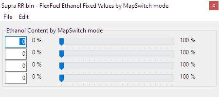
FlexFuel Knock Threshold (cylinder 1-6)
Sets a knock value for reading knock for each cylinder. This value is multiplied by the map FlexFuel Knock Threshold Blend to make proportional adjustments to knock sensitivity based on the ethanol content. This can be helpful in some instances as we've seen knock sensors react differently than on gasoline when running ethanol due to harmonic differences in the combustion. If you encounter persistent ignition retard when running moderate concentrations of ethanol, increasing the knock thresholds here by 10% may be a good starting point. Proper tuning of these maps really requires an external knock monitoring device to corroborate the ECU's own knock detection.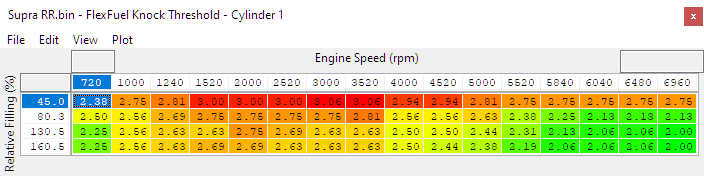
FlexFuel Knock Threshold Blend
Multiplier value based on ethanol content. This value is multiplied against the FlexFuel Knock Threshold map for each cylinder in order to establish a different threshold of knock for different ethanol contents.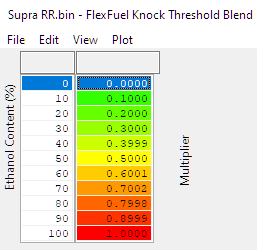
Flex Fuel Load Limit
Makes adjustments to the Load Limit based on ethanol content and RPM. Allows you to run more or less load (boost) based on ethanol content.
Typical uses for this map are to prevent excessive fuel system load, by limiting airflow at high ethanol concentrations, or to limit load when there is insufficient octane due to low ethanol concentration.
This map is active when FlexFuel is enabled, regardless of what setting of "Use RaceROM load limit maps" is in RaceROM Special Features→Enable Special Features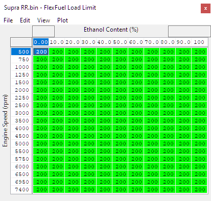
FlexFuel Sensor Failure Error Mask
The output value from the sensor should it detect an error.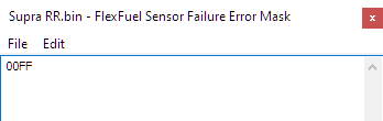
Flex Fuel Sensor Failure Ethanol Content
In the event of a sensor failure the ethanol content will default to this value for purposes of engine operation. If a customer typically runs on pump gas or ethanol exclusively it's good practice to set it to that value. If they typically run a blend, finding a safe middle ground is the best bet.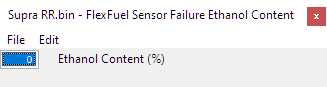
Flex Fuel Sensor Failure Load Limit
Maximum Load Limit if an ethanol content sensor failure is detected. Reduces output when the ECU isn't sure of what the ethanol content is.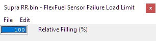
| Warning |
|---|
For additional information on Ethanol Content Sensor setup, check out the RaceROM CAN Input section |
RaceROM Logging Parameters
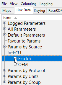
Along with the new RaceROM code we were able to add in several loggable paramters in addition to the ones pertaining specificaly to RaceROM features. These items can either be viewed live or datalogged through the ProECU software or the ECUConnect APP. These specific parameters can be found under the Params by Source section under EcuTek
For information on how to log these items check out our guides:
- AntiLag Flags
- AntiLag Ignition Request (° BTDC)
- AntiLag Target (seconds)
- AntiLag ReArm Timer (seconds)
- AntiLag Run Timer (seconds)
- Boost Target (hPa)
- Burble Aggression (RaceRom)
- Burble Ignition Delta (° BTDC)
- Burble Ignition Minimum (° BTDC)
- CAN Output Byte 1
- CAN Sensor Channel 1-8
- CAN Sensor Ethanol Content
- CAN Sensor Fuel Temperature
- CAN Sensor Lambda
- CAN Sensor Status
- Compressor Pressure Ratio Target
- Cruise Buttons
- Custom Input 1-8
- Custom Map (A-P) Interim
- Custom Map (A-P) Result
- Cylinder Fill (%)
- Cylinder Fill Limit (%)
- Cylinder Fill Reason
- Debug: CAN MsgObj Cruise
- Debug: CAN MsgObj Custom
- Debug: CAN MsgObj Output
- Dig: Torque Limit Reason
- Engine Speed (rpm)
- Exhaust Gas Temperature (°C)
- Exhaust Mass Flow Target (kh/h)
- Flex Fuel Cranking Multiplier
- Flex Fuel Ethanol Content (%)
- Flex Fuel Ignition Adjustment
- Flex Fuel Lambda Adjustment
- Flex Fuel Quantity Multiplier (-)
- Ignition Blend Factor (° Crank)
- Knock Retard Average (° Crank)
- Knock Retard Cylinder 1-6
- Load Factor for Component Protection
- Manifold Pressure Target (Normalised)
- RaceROM Controller Power (Nm)
- RaceROM Controller Torque (Nm)
- Torque Desired Max (Nm)
- Torque Request (Nm)
- Turbine Inlet Pressure (hPa)
- Turbine Mass Fraction
- Turbine Power Base (kw)
- Turbine Power Derivative (kw)
- Turbine Power Final (kw)
- Turbine Power Proportional (kw)
- Vehicle Use Case
- Wastegate Position Integral (%)
RaceROM Custom Maps
Our custom maps system currently supports the following outputs, meaning you can make your own maps to fully control any of the following items.
See our other custom map manual for more information.
One point worth noting is to be careful of what value you're replacing or outputting to. Many values and tables are fairly interconnected in this system so it may have unintended affects for driveability etc.
Input / Activation Channels
- Accelerator Position
- Ambient Air Temperature
- Barometric Pressure
- Battery Voltage
- Boost Pressure
- Boost Pressure Error
- Boost Pressure Target
- Cam Angle Exhaust
- Cam Angle Inlet
- Cruise Buttons
- Cylinder Fill Actual
- Cylinder Fill Desired
- Engine Oil Pressure
- Engine Temperature
- Engine Speed
- Exhaust Gas Temperature
- FlexFuel Ethanol Content
- Fuel Pressure
- Fuel Temperature
- Gear
- Gearbox Temperature
- Intake Air Temperature
- Lambda Actual
- Lambda Target Limit
- Lateral G
- Longitudinal G
- Manifold Absolute Pressure
- Mapswitch Mode
- Mass Airflow
- Torque Actual
- Torque Target
- Vehicle Speed
- Custom Map Result (A-P)
- Custom Input (1-5)
- CAN Sensor Channel (1-8)
- CAN Sensor Ethanol
- CAN Sensor Fuel Temp
- CAN Sensor Status
- RaceROM Controller Torque
- RaceROM Controller Power
Output Channel
- Calculation 1 (custom maps)
- Calculation 2 (custom maps)
- Sports Display Torque (%)
- Sports Display Power (%)
- Boost Target (hpa)
- Cam TIming Inlet (60-120 deg)
- Cam Timing Exhaust (75-135 deg)
- Inlet Valve Lift (mm)
- Ignition Timing (deg)
- Fuel Rail Pressure (MPa)
- Rev Limit (RPM)
- The factory Rev limit is fairly slow to react so this shouldn't be used as a "Hard" cut.
- Lambda Target
- Fuel Multiplier (n)
- Fuel Ethanol Content (%)
- Torque Desired Max (Nm)
- Vehicle Speed Limit (km/h)
- Burble Aggression (%)
- Cylinder Fill Max (%)
- Exhaust Flap (0-1)
- Fuel Pump Speed Desired (RPM)
- AntiLag Boost Target (hpa)
- Wastegate Target Position (%)
- Torque Request (Nm)
- If you adjust the torque request, be cautious of where, when and how you adjust the value. For example you wouldn't want to set it to target 500 ft/lbs everywhere as that would be regardless of throttle input and lead to very poor driveability.
Output Function
- Replace Channel value with map output
- Add map output to channel value
- Multiply channel value by map output
- Use map output as a minimum for channel value
- Use map output as a maximum for channel value
- Add map output to integral. Add integral to channel value
- Add map output to integral. Multiply channel value by integral
| Warning |
|---|
EcuTek ProECU tuning tools tools should only be used by experienced tuners who understand the product and engine calibration.
Retail customers ** If you have any doubt that you do NOT have the experienced required to use this product then you should NOT USE IT, you should simply contact your EcuTek Master Tuner shown clearly on the top of your Programming Kit or visit your preferred tuning shop to have a professional tuner to use it for you ** |
| Insert excerpt | ||||||
|---|---|---|---|---|---|---|
|