B58 / A90 Supra RaceROM Supplement
![]()
RR Tuning Guide
Per Gear Maximums
These tables are still affected by load and torque limits, as such those will need to be modified if targeting values higher than those limits.
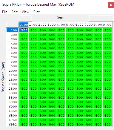
Torque Desired Max (RaceROM)
This table allows you to set a desired max amount of torque per gear by RPM. This torque request is scaled but the output of the driver demand maps such as Torque - Driver→Pedal Request - Drive AT and related maps.
Only used when "Use RaceROM torque desired max maps" is enabled in RaceROM Special Features→Enable Special Features and overwrites the values from the map Torque - Engine→Clutch Torque Maximum (which can be left stock if the RaceROM map is enabled and calibrated).
If Flexfuel is also enabled, it's blended with RaceROM FlexFuel->Torque→FlexFuel Torque Desired Max
Torque Desired Max Scalar by MS Mode (RaceROM)
Allows a percentage multiplier to be applied to the Torque Desired Max (RaceROM) table based on map slot. This can be handy to allow map modes of varying power levels for use with different drivers / driving conditions. These can be customised further to allow for different percentage changes for normal vs sport mode.
Map modes are in a descending order with the top of each section being slot 1.

The final output of the RaceROM Torque Desired Max be logged using the Torque Desired Max logging parameter.
Torque Request Multiplier
Since the factory torque requests from the pedal are percentage based, as you increase the amount of torque being targeted either through the RaceROM maps, Flex Fuel (or even the stock maps) you can run into some undesireable behavior. At low throttle positions you'll still be requesting the same percentage of torque, but because your targets are higher, you'll be targeting more torque than you'll really want to see at those lower pedal positions or gears.
For example, if you're targeting 20% more torque than stock, than you'll also be targeting 20% more torque than stock at 2% throttle.
This table provides a function allowing you to set a multiplier curve to adjust the sensitivity of the accelerator pedal per map slot to target a lower level of torque than it would otherwise be trying to reach. This works in conjunction with the factory Torque-Driver → Pedal Request maps.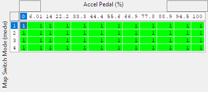
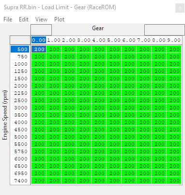
Load Limit - Gear (RaceROM)
This table allows you to set different load limits by RPM per gear, they are used in conjunction with the OEM load limits. The lowest value from any of the active limits will set the final limit on the target load.
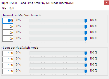
Load Limit Scalar by MS (map slot) Mode
This map sets a percentage multiplier to the Load Limit -Gear (RaceROM) value by map slot. This can be handy to have map modes of varying power levels for use with different drivers / driving conditions. These can be customised further to allow for different percentage changes for normal vs sport mode.
Map modes are in a descending order with the top of each section being slot 1.
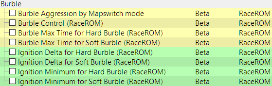
Burble Control
The burble control allows the tuner to configure maps for soft and hard burble. The ECU will interpolate between these maps based on the Burble Aggression parameter which can be configured independently for each mapswitch mode and also through custom maps if you want to control it from a cell phone. For further information check out our guide below.
Ignition Base Timing Maps & Lambda / Fuel Maps
Map switching allows you to switch between multiple versions of the Ignition and fuel maps allowing for different driving behavior in different maps. Keep in mind that these tables may come before other compensations. If you see it running at a different value than you expect, make sure your other limits and safeties aren't coming in to play.
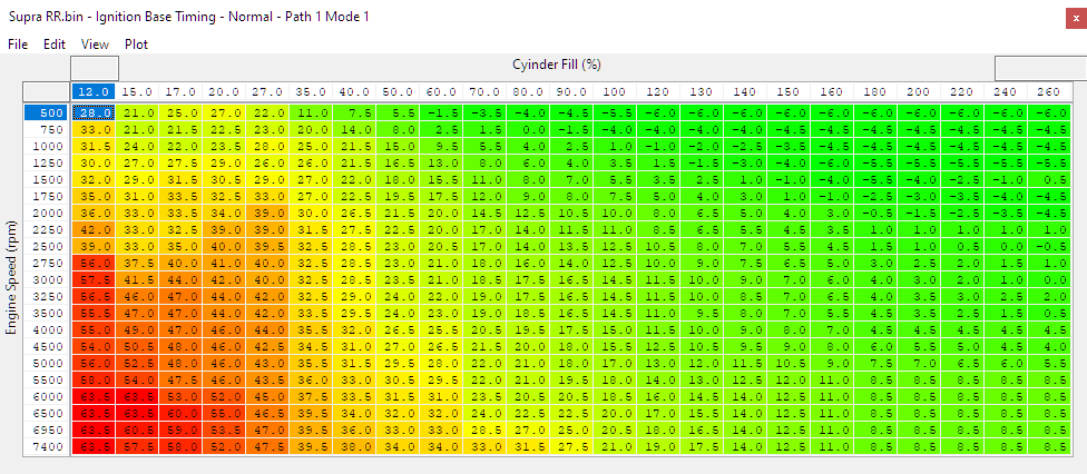
Ignition Base Normal/Safe Timing Mode 1-4
Uses Cylinder Fill % (x-axis) and engine speed in RPM (y-axis) to set base ignition timing in normal mode and safe mode. Replaces the factory Ignition Base Timing Offset Multiplier map. Once the RaceROM maps are activated the base map will no longer operate.
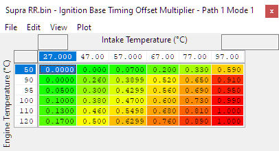
Ignition Base Timing Offset Multiplier
Applies a multiplier to the Ignition Base Timing maps using Engine Temperature (Coolant) and Intake Temperature to modify the timing for varying environmental conditions.
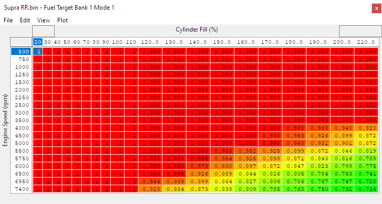
Fuel Target Bank 1 Mode 1-4
Sets the fuel target for bank the engine using Cylinder Fill % (x-axis) and engine speed in RPM (y-axis). Replaces the factory Fuel Target Bank 1 map. Once the RaceROM maps are activated the base map will no longer operate.
These tables have additional resolution (rows and columns) when compared to the factory map. As such you may need to interpolate some of the cells from your factory map if it was tuned previously, rather than simply copy and pasting it in.
Valet Mode
Selecting Valet Mode
Enabling Valet Mode in the software can be done easily by navigating to the Enable Special Features Map and toggling the Valet Mode option.

How to Use Valet Mode
Press the cruise control UP button until the rev counter reads 7
Temperature gauge will show 6 bars for valet mode OFF, or 7 bars for valet mode ON.
Press the RES/CNCL button to select ON or OFF as desired.
When valet mode is enabled, the torque and max speed of the vehicle is limited according to the distance travelled.It can be used to prevent misuse of the vehicle or as an additional anti-theft measure to complement the inbuilt security.
There are two different steering wheel options. Make sure you're pressing the correct button.
/wiki/spaces/SUPPORT/pages/469729366
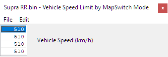
Vehicle Speed Limit Override
RaceROM has its own vehicle speed limit maps which override the limit set in the vehicle coding. These can be set per map-Switch Mode

Saving Selections at Key Cycle
Depending on the circumstances, you may or may not want your mode selections to persist after a key cycle. The mapswitch mode, torque/power settings, custom inputs (from ECUconnect app) and valet mode settings can be backed up into the EEPROM when the ignition is turned off, and restored when you start up again.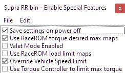
ECU Connect APP Integration
Using the ECU Connect you're able to manipulate things like burbles, map slots, or even change values within custom maps. For a guide on how to do this check out our guide
RaceROM Custom Input
The Custom CAN input feature in RaceROM allows you to import CAN data from an external sensor such as a wideband or ethanol content analyser.
Installation
The BMW ECU has three CAN channels (PT-CAN, PT-CAN2 and K-CAN5), none of them are directly connected to the OBD port. You cannot connect the CAN sensor to the OBD port. You must connect the CAN sensor directly to one of these buses. Suggested connection points are near the ECU in the engine bay or the Front Electronic Module in the passenger footwell.
The pins you'll want to utilise for this system can be found on Connector A46*1B as shown in the diagram below.
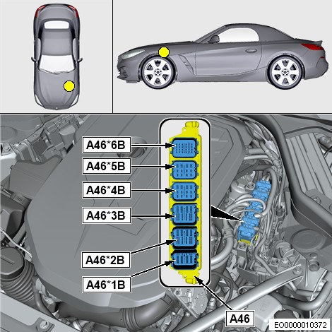
- PT-CAN bus is ECU connector A46*1B pins 41 & 42.
- PT-CAN2 bus is ECU connector A46*1B pins 35 & 36.
- K-CAN5 bus is ECU connector A46*1B pins 33 & 34.
CAN Sensor Configuration
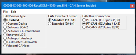
In the CAN Sensor Enabled map you'll be able to select your CAN sensor type from a list of pre-configured items, or custom devices. Note that the presets only apply if you're using the standard CAN ID of the unit.
If you set your CAN device to use a custom CAN ID you'll need to input the value manually.
RaceROM Custom CAN Output
This feature allows you to configure the ECU to output a custom packet onto one of its CAN buses. This packet can be used to pass data over the CAN bus from the ECU to another module such as a custom display or water/meth injection controller. In future we plan to include pre-calibrated profiles for a selection of supported devices, but currently there are just two options, "Custom Device" that you can configure yourself, and "EcuTek Test Packet" that will output a packet containing "EcuTek" followed by a sequence number and a checksum.
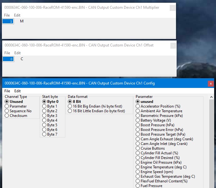
With control of up to 8 parameters (channels) to be included in the packet. You can scale each channel to ensure that its expected range of values fits into 8 bits (0-255) or 16 bits (0-65535).
A channel can contain either a constant value, a parameter, a sequence number (heartbeat), or a CRC8 checksum of the other bytes in the packet.
For each channel, you specify the start byte within the packet, and the format, 8 or 16 bits (big or little endian). The total number of bytes you can output in the packet is 8. Most CAN packets send the full eight bytes, even if some of them are not used, but you can send a shorter packet if you need to.
For example, you could configure channel 1 and 2 to output 16 bit values, starting at byte 1 and 3 respectively, then channels 3, 4 and 5 as 8 bit values starting at bytes 5,6 and 7. Then channel 6 as a checksum at byte 8. Channels 7 and 8 would remain unused.
To send a constant value, select parameter, then set the parameter type as unused, then specify the constant in the offset map for that channel. The sequence number will increment for every packet from 00 to FF and then rolls over to 00 and counts up again.
example
In this example
- Channel1 is engine speed, which is configured as a 16 bit value starting at byte0.
- Channel2 is Temperature, which is configured as an 8 bit value starting at byte2.
- Channel3 is Accel Pedal, which is configured as an 8 bit value starting at byte3.
- Channel4 is Gear, which is configured as an 8 bit value starting at byte4.
- Channel5 comes from the ECUconnect app, allowing the external module to be controlled from a cell phone. This goes to byte5.
- Channel6 comes from a Custom Map, allowing the result of a complex calculation to be send to the external module. This goes to byte6.
- Channel7 goes to byte7 and is a non-inverted CRC8 checksum of all the other bytes in the packet.
- Channel8 is not used in this example, because there is no more space in the packet.
If we wanted to include another parameter in this packet then we could put a multiplier of 0.02 (ie. divide by 50) on channel1 and store the RPM as an 8 bit value in byte0. Then we could define our new parameter in channel8 to output an 8 bit value in byte1.
There is no requirement to keep the channel numbers aligned to their original byte position in the output packet.

For additional information on Ethanol Content Sensor setup and failsafes, check out the RaceROM Flex Fuel section
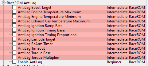
RaceROM Antilag
The Antilag feature is designed for roll racing. It is similar to the Rolling Launch feature in our GTR product. The objective is to spin up the turbo and create a reserve of boost in anticipation of rapid acceleration.
To Use
- Ensure the cruise control system is deactivated.
- While driving forward press and hold the cruise control "Set" button, you can adjust the speed by modulating the accelerator. Increased input will demand slightly higher torque and allow subtle acceleration and vice-versa.
- When the driver wishes to launch simply release the cruise "Set" button.
While activated, the Antilag feature selects a boost target (default 1800hpa) and applies closed-loop ignition retard to generate more exhaust gas energy and help maintain that target.
Best results can be achieved by manually selecting a suitable gear prior to activating the feature, if used in auto, the accelerator pedal input will cause a downshift.
There are two different steering wheel options. Make sure you're pressing the correct button.
/wiki/spaces/SUPPORT/pages/469729366
Enable AntiLag
Switch that activates AntiLag system per map slot mode. Also provides the option to force the Exhaust Flap open to increase flow on map slots where you're using the AntiLag system.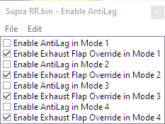
AntiLag Boost Target
Establishes a boost the ECU will attempt to achieve while the anti-lag system is active. The four settings are for the 4 map switching modes.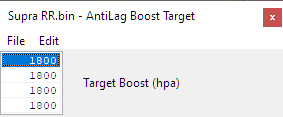
AntiLag Engine Temperature Maximum
Sets a Maximum (high) temperature the engine coolant temperature must be below in order for the AntiLag system to engage. Since this system can cause an increase in coolant temperature it's a good idea to keep this at a reasonable level to prevent overheating or engine damage.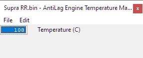
AntiLag Engine Temperature Minimum
Sets a minimum (low) temperature the engine coolant temperature must be above in order for the AntiLag system to engage. Keeping this to a sane value ensures that the car is up to proper operating temperature before using engaging the system.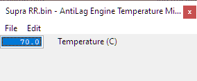
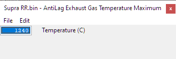
AntiLag Exhaust Gas Temperature Maximum
Sets a Maximum (high) temperature the exhaust gas temperature must be below in order for the AntiLag system to engage. Because this system can cause an increase in temperature as a result of using the AntiLag feature it's important to keep the exhaust gas temperature to a safe temperature to avoid damage to engine components.
AntiLag Ignition Ramp Rate
Establishes the rate in degrees of ignition timing the system will alter ignition timing over a period of time.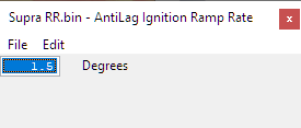
AntiLag Timing Base
Base values the system will use to alter ignition timing when the system is activated. These are adjusted over time by the ramp rate and the AntiLag Ignition TIming Proportional in order to hit the desired boost level.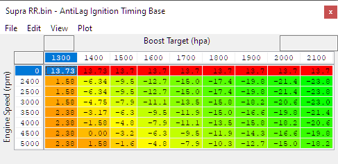
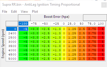
AntiLag Ignition Timing Proportional
The change to existing ignition timing after the AntiLag Timing Base values are applied that the system will utilise in order to correct for boost error (failure to meet or maintain the AntiLag Boost Target)
AntiLag Lambda Target
The fuel target the AntiLag system will use while the AntiLag system is active.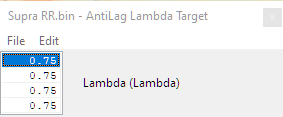
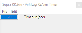
AntiLag ReArm Timer
In order to prevent heat buildup or damage we recommend not using the AntiLag system continuously without allowing the engine to properly cool down in between. This value sets an amount of time that must pass before the system can be activated again.
This either begins after AntiLag was just used, or if the system shut it down due to the AntiLag Timeout value being exceeded.
AntiLag Timeout
Amount of time the AntiLag system can be active before shutting down. An important value as the system generates a lot of heat in the turbocharger and exhaust which can be damaging.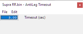
AntiLag Torque Base
Adjustment to the torque request based on gear. Important to maintain speed as higher gears will require more torque in order to keep the same amount of speed.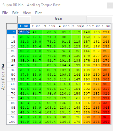
AntiLag Torque Multiplier
Works in conjunction with the AntiLag Torque Base table. Applies a multiplier to that value to adjust for the added torque required at higher vehicle speeds to maintain speed when the system is active.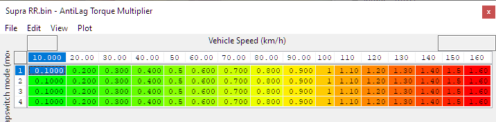
FlexFuel Ethanol Fixed Values by Mapswitch Mode
Sets a constant ethanol content per mapswitch mode. Only utilised if selected in the FlexFuel Enable map. See above for more details.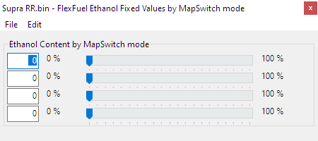
FlexFuel Knock Threshold (cylinder 1-6)
Sets a knock value for reading knock for each cylinder. This value is multiplied by the map FlexFuel Knock Threshold Blend to make proportional adjustments to knock sensitivity based on the ethanol content. This can be helpful in some instances as we've seen knock sensors react differently than on gasoline when running ethanol due to harmonic differences in the combustion. If you encounter persistent ignition retard when running moderate concentrations of ethanol, increasing the knock thresholds here by 10% may be a good starting point. Proper tuning of these maps really requires an external knock monitoring device to corroborate the ECU's own knock detection.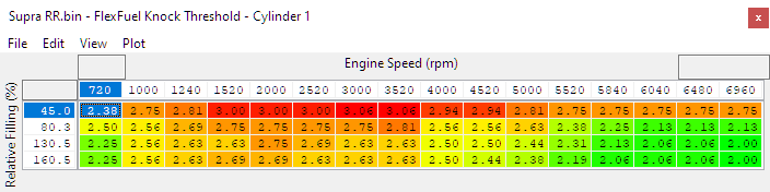
FlexFuel Knock Threshold Blend
Multiplier value based on ethanol content. This value is multiplied against the FlexFuel Knock Threshold map for each cylinder in order to establish a different threshold of knock for different ethanol contents.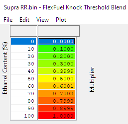
Flex Fuel Load Limit
Makes adjustments to the Load Limit based on ethanol content and RPM. Allows you to run more or less load (boost) based on ethanol content.
Typical uses for this map are to prevent excessive fuel system load, by limiting airflow at high ethanol concentrations, or to limit load when there is insufficient octane due to low ethanol concentration.
This map is active when FlexFuel is enabled, regardless of what setting of "Use RaceROM load limit maps" is in RaceROM Special Features→Enable Special Features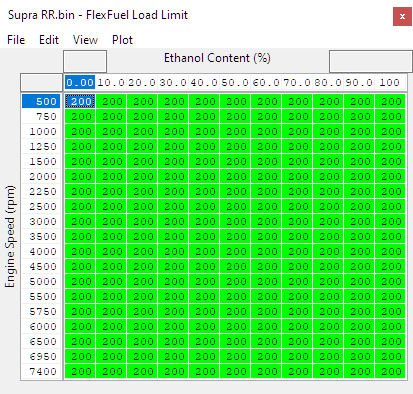
FlexFuel Sensor Failure Error Mask
The output value from the sensor should it detect an error.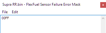
Flex Fuel Sensor Failure Ethanol Content
In the event of a sensor failure the ethanol content will default to this value for purposes of engine operation. If a customer typically runs on pump gas or ethanol exclusively it's good practice to set it to that value. If they typically run a blend, finding a safe middle ground is the best bet.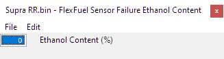
Flex Fuel Sensor Failure Load Limit
Maximum Load Limit if an ethanol content sensor failure is detected. Reduces output when the ECU isn't sure of what the ethanol content is.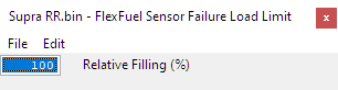
For additional information on Ethanol Content Sensor setup, check out the RaceROM CAN Input section
RaceROM Logging Parameters
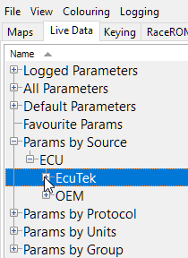
Along with the new RaceROM code we were able to add in several loggable paramters in addition to the ones pertaining specificaly to RaceROM features. These items can either be viewed live or datalogged through the ProECU software or the ECUConnect APP. These specific parameters can be found under the Params by Source section under EcuTek
For information on how to log these items check out our guides:
- AntiLag Flags
- AntiLag Ignition Request (° BTDC)
- AntiLag Target (seconds)
- AntiLag ReArm Timer (seconds)
- AntiLag Run Timer (seconds)
- Boost Target (hPa)
- Burble Aggression (RaceRom)
- Burble Ignition Delta (° BTDC)
- Burble Ignition Minimum (° BTDC)
- CAN Output Byte 1
- CAN Sensor Channel 1-8
- CAN Sensor Ethanol Content
- CAN Sensor Fuel Temperature
- CAN Sensor Lambda
- CAN Sensor Status
- Compressor Pressure Ratio Target
- Cruise Buttons
- Custom Input 1-8
- Custom Map (A-P) Interim
- Custom Map (A-P) Result
- Cylinder Fill (%)
- Cylinder Fill Limit (%)
- Cylinder Fill Reason
- Debug: CAN MsgObj Cruise
- Debug: CAN MsgObj Custom
- Debug: CAN MsgObj Output
- Dig: Torque Limit Reason
- Engine Speed (rpm)
- Exhaust Gas Temperature (°C)
- Exhaust Mass Flow Target (kh/h)
- Flex Fuel Cranking Multiplier
- Flex Fuel Ethanol Content (%)
- Flex Fuel Ignition Adjustment
- Flex Fuel Lambda Adjustment
- Flex Fuel Quantity Multiplier (-)
- Ignition Blend Factor (° Crank)
- Knock Retard Average (° Crank)
- Knock Retard Cylinder 1-6
- Load Factor for Component Protection
- Manifold Pressure Target (Normalised)
- RaceROM Controller Power (Nm)
- RaceROM Controller Torque (Nm)
- Torque Desired Max (Nm)
- Torque Request (Nm)
- Turbine Inlet Pressure (hPa)
- Turbine Mass Fraction
- Turbine Power Base (kw)
- Turbine Power Derivative (kw)
- Turbine Power Final (kw)
- Turbine Power Proportional (kw)
- Vehicle Use Case
- Wastegate Position Integral (%)
RaceROM Custom Maps
Our custom maps system currently supports the following outputs, meaning you can make your own maps to fully control any of the following items.
See our other custom map manual for more information.
One point worth noting is to be careful of what value you're replacing or outputting to. Many values and tables are fairly interconnected in this system so it may have unintended affects for driveability etc.
Input / Activation Channels
- Accelerator Position
- Ambient Air Temperature
- Barometric Pressure
- Battery Voltage
- Boost Pressure
- Boost Pressure Error
- Boost Pressure Target
- Cam Angle Exhaust
- Cam Angle Inlet
- Cruise Buttons
- Cylinder Fill Actual
- Cylinder Fill Desired
- Engine Oil Pressure
- Engine Temperature
- Engine Speed
- Exhaust Gas Temperature
- FlexFuel Ethanol Content
- Fuel Pressure
- Fuel Temperature
- Gear
- Gearbox Temperature
- Intake Air Temperature
- Lambda Actual
- Lambda Target Limit
- Lateral G
- Longitudinal G
- Manifold Absolute Pressure
- Mapswitch Mode
- Mass Airflow
- Torque Actual
- Torque Target
- Vehicle Speed
- Custom Map Result (A-P)
- Custom Input (1-5)
- CAN Sensor Channel (1-8)
- CAN Sensor Ethanol
- CAN Sensor Fuel Temp
- CAN Sensor Status
- RaceROM Controller Torque
- RaceROM Controller Power
Output Channel
- Calculation 1 (custom maps)
- Calculation 2 (custom maps)
- Sports Display Torque (%)
- Sports Display Power (%)
- Boost Target (hpa)
- Cam TIming Inlet (60-120 deg)
- Cam Timing Exhaust (75-135 deg)
- Inlet Valve Lift (mm)
- Ignition Timing (deg)
- Fuel Rail Pressure (MPa)
- Rev Limit (RPM)
- The factory Rev limit is fairly slow to react so this shouldn't be used as a "Hard" cut.
- Lambda Target
- Fuel Multiplier (n)
- Fuel Ethanol Content (%)
- Torque Desired Max (Nm)
- Vehicle Speed Limit (km/h)
- Burble Aggression (%)
- Cylinder Fill Max (%)
- Exhaust Flap (0-1)
- Fuel Pump Speed Desired (RPM)
- AntiLag Boost Target (hpa)
- Wastegate Target Position (%)
- Torque Request (Nm)
- If you adjust the torque request, be cautious of where, when and how you adjust the value. For example you wouldn't want to set it to target 500 ft/lbs everywhere as that would be regardless of throttle input and lead to very poor driveability.
Output Function
- Replace Channel value with map output
- Add map output to channel value
- Multiply channel value by map output
- Use map output as a minimum for channel value
- Use map output as a maximum for channel value
- Add map output to integral. Add integral to channel value
- Add map output to integral. Multiply channel value by integral
EcuTek ProECU tuning tools tools should only be used by experienced tuners who understand the product and engine calibration.
If you do not fully understand this product then you WILL damage your engine, ECU or your vehicle.
Please ensure you fully read all EcuTek manuals BEFORE attempting to use ProECU with your laptop or your vehicle.
Use with extreme caution and understanding at all times, if in doubt then do not proceed.
EcuTek accepts no responsibility for any damage to the engine, ECU or any part of the vehicle that results directly or indirectly from using the product.
** If you are in any doubt that you do NOT have the experienced required to use this product then you should NOT USE IT **
Retail customers
** If you have any doubt that you do NOT have the experienced required to use this product then you should NOT USE IT, you should simply contact your EcuTek Master Tuner shown clearly on the top of your Programming Kit or visit your preferred tuning shop to have a professional tuner to use it for you **
An alphabetical list of technical acronyms and terms with explanations (where terms are not self-explanatory)
- Accelerator pedal maps
The ECU maps that relate pedal opening percentage and throttle butterfly valve angle. - ACT (Air Charge Temperature)
Also written as AIT (Air Intake Temperature) or CAT (Charge Air Temperature). - Active Regeneration
Diesel particulate filter clearing, which is carried out when required by the engine management system, which raises exhaust temperature by temporarily introducing a particular mode of engine operation. - Advance Multiplier
The degree of ignition timing advance between the ignition base map and the maximum ignition timing, which is limited either by a secondary 'max' map or an additional advance map. - AFM (AirFlow Meter)
Continuously measures the flow of engine intake air. - AFR (Air Fuel Ratio)
The ratio of intake air to injected fuel. 14.7:1 is the ideal 'stoichiometric' ratio, which means the ideal ratio at which all oxygen is consumed and all fuel is burned. - AT
Automatic Transmission - AIT (Air Intake Temperature)
Also sometimes written as CAT (Charge Air Temperature) - APS
Accelerator Pedal Position - ASC (Adaptive Shift Control)
Nissan's 'learning' auto-transmission control, which adapts shifting style to the driver's preferences and road conditions. - Auto blip
The management system's brief burst of engine revs to allow the driver to downshift under braking. - AVS
Audi Valve lift System - BLD
Border line Detonation - CAF (Calculated AirFlow)
Where the airflow sensor voltage does not have a linear relationship to the flow, the ECU uses a scaling map to translate sensor voltage into an airflow rate value. - CAN/CANbus (Controller Area Network)
A vehicle bus standard that allows microcontrollers and devices to communicate with each other in applications without a host computer. Originally designed for multiplexing vehicle electrical wiring. - CAT (Charge Air Temperature)
Sometimes also written as ACT (Air Charge Temperature) or AIT (Air Intake Temperature) and not to be confused with Cat - an abbreviation for catalytic converter. - CEL
Check Engine Light - Closed Loop
Control based on feedback, or input responding to output. A feedback control loop is used in three-way catalytic converter systems and various electronic circuits. - Colour by Lambda
EcuTek software feature that provides an easy, live visual representation of fuel/air mixture changes. - Colour by Knock
EcuTek software feature that provides an easy, live visual representation of cylinder knock characteristics.
Custom Datalogging
Allows the logging of 50 or more custom parameters not available from the factory ECU - Custom Gauge (see also Gauge Hijack)
This allows the tuner to display a fixed value or the output of a custom map on the dashboard gauges, the exact functionality depending on the type of gauge cluster fitted to the car. It can be used, for example, to display the required fuel octane for each map switch mode, to display the current AFR or the output of an external ethanol content sensor - Custom Maps
Bespoke new maps added by Ecutek for increased functionality - CVN (Checksum Verification Number)
A checksum is a small datum from a block of digital data, whose purpose is to detect errors that may have been introduced during its transmission or storage. Usually applied to an installation file after it is received via a download - DBW (Drive By Wire)
The use of electrical or electromechanical systems for performing vehicle functions traditionally achieved by mechanical linkages - DCT
Dual Clutch Transmission - DeltaDash
An early EcuTek software data logger for Subaru cars, whose functionality is now incorporated in the ProECU product - DI (Direct Injection or Direct Injector)
The favoured petrol engine technology in which fuel is injected into the combustion chamber rather than the inlet port - DLC
Diagnostic data Link Connector - Dongle
A small hardware device (such as the ProECU Licence Key USB dongle) which connects to another device, typically a computer, to provide it with added functionality, copyright protection or product licensing - DPF (Diesel Particulate Filter)
A carbon-particle (soot) trap in the exhaust system of a diesel
DTC (Diagnostic Trouble Code)
A trouble/fault code generated and stored by the engine management when it detects a problem - DSG
Direct Shift Gearbox - DTC
Diagnostic Trouble Code, also referred to as CEL codes (check engine light) - DQ
Transverse Mounted DSG Gearbox - ECO
Economy - ECT
Engine Coolant Temperature - ECU
Engine Control Unit. The computer for the powertrain of the vehicle. Also called PCM, ECM, PCU etc. from various manufacturers - EGR
Exhaust Gas Recirculation - EGT
Exhaust Gas Temperature - Engine Load
AirFlow divided by engine RPM; effectively how much air enters the engine per revolution. It may be expressed as a percentage of cylinder fill - EOI (End of Injection)
Stipulated as an angle, in degrees - ESP (Electronic Stability Program)
Also Dynamic Stability Control, is onboard computer technology that improves vehicle stability by detecting loss of traction or steering control and intervening to correct it via the antilock braking system and engine control - Equivalence Ratio
The desired closed-loop AFR that the management ECU attempts to meet - EX
Exhaust - Fail Safe
A device or function attribute that, in the event of a specific type of failure, responds in a way that minimises or negates harm to other devices or persons - FastFlash
EcuTek's rapid system of ROM programming by block, where all code is built into the ECU - FI (Forced Induction)
Boosted air charge, as with supercharging and turbocharging - Flash Licence (EcuTek)
See 'Dongle' previously - FFS (Flat-Foot Shifting)
An EcuTek ProECU feature that lets you keep your foot flat on the accelerator while changing gear so as to minimise change time and keep up engine speed and torque, maximising acceleration in the next gear up - FlexFuel (Also Dual Fuel)
Refers to an engine that runs on more than one fuel (eg petrol and ethanol) and both fuels share the same fuel tank - FMIC
Front Mounted Intercooler - Forced Induction
Utilizing a supercharger or turbocharger to force air into the intake tract of a vehicle. See NA / Naturally Aspirated - FPW (Fuel Pulse Width)
The duration of opening of each injector in milliseconds (ms) - FT (Fuel Trim)
A system-integrated ability to automatically make small adjustments to fuel metering to compensate for certain factors affecting engine operation - FTLT (Fuel Trim Long Term)
Fuelling compensation applied on long-term basis - FTST (Fuel Trim Short Term)
Fuelling compensation applied on short-term basis - Gauge Hijack (see also Custom Gauge)
The temporary reassignment of certain dashboard instruments via EcuTek software in order to display other functions such as AFR, Boost, Fuel Trims or Map Switch modes - Hybrid Speed Density
A programmable function that allows switching between MAP and MAF airflow sensing for the Engine Load calculation depending on operating conditions - Hysteresis
A slight margin for variation, or 'cushion zone', particularly with reference to a predetermined rev limit - Idle Learning
A program feature that balances idling parameters - particularly on a dual-intake system such as that of the Nissan GT-R - IMRC (Intake Manifold Runner Control)
Or Intake Manifold Swirl Control (IMSC), a vacuum and solenoid-actuated system that partially closes an intake duct to generate intake air turbulence under low-power running - IMSC (Intake Manifold Swirl Control)
Or Intake Manifold Runner Control (IMRC), a vacuum and solenoid-actuated system that partially closes an intake duct to generate intake air turbulence under low-power running - IN
Intake - Injector Scaling
The recalibration of fuel injector characteristics (parameters such as flow rate, pulse width etc) to suit engine modifications - ISS (Intercooler Spray System)
A coolant-spraying mechanism that maximises intercooler efficiency and is used on a few high-performance turbocharged cars - K-Factor
A Nissan-specific multiplier for the manufacturer's base fuel schedule - a figure best left unchanged - K-Line
A pre-CANbus communications data-transmission line and protocol still occasionally used in conjunction with a CANbus - Knock Correction
The amount of ignition timing correction (positive or negative) set by the ECU in response to cylinder knock, or its absence - Knock Retard
The amount of ignition timing retardation set by the ECU in response to detected cylinder knock - Lambda Sensor (O2 Sensor)
A sensor in a petrol-engine exhaust system that continuously measures the concentration of oxygen in the exhaust gases - Launch Control
An electronic aid - effected via a number of management functions - that assists drivers of both racing and street cars to accelerate cleanly (ie with minimal wheelspin) from a standing start - LBT
Lean Best Torque - Limp-Home
A reduced-performance mode of engine operation adopted by the management system when certain engine faults are detected - Live Data
Data streamed from the management ECU as the engine is running - MAF (Mass Air Flow)
As in MAF Sensor; the amount of air flowing is stipulated in grammes per second (g/s) - MAF Bank Switching
A feature that allows airflow measurement correction after the fitting of an aftermarket intercooler that swaps airflow between cylinder banks - MAP (Manifold Absolute Pressure)
As in MAP sensor, whose output is stipulated in psi or bar - Map Switching
The selection of an alternative engine management map via a 'hijacked' or 're-purposed' control in the car - Master Tuner (Ecutek)
Master Tuners are the most experienced category of engine tuners (as determined by EcuTek) and have the authority to purchase ProECU Programming Kits and retail them to vehicle owners together with their own ECU calibrations - MBT (Maximum Best Torque/Minimum Best Timing/Maximum Brake Torque)
Can also be understood as 'minimum timing advance for best torque' - MQB
Modularer Querbaukasten (Modular Transverse Platform used by VAG in such vehicles as the GTI, Audi A3) - MLB
Modularer Langsbaukasten (Modular Longitudinal Platform used by VAG in such vehicles as the Audi A4, A5) - MRP (Manifold Relative Pressure)
Negative or positive inlet manifold pressure relative to atmospheric pressure - MPI
Manifold Port Injection or Multi-Port Injection - MT
Manual Transmission - NA (Naturally Aspirated) Also refferred to as NASP
Unboosted, neither turbocharged nor supercharged - Nm (Newton Metre)
A metric unit of measurement for torque. 1 Nm ≈ 0.73756215 lbft
- OBD (On Board Diagnostics)
A general term for a vehicle's self-diagnostic and reporting capabilities; OBD systems give access to the status of the various vehicle sub-systems - OBD-II (On Board Diagnostics)
The current OBD standard capable of providing real-time data and a standardised series of diagnostic trouble codes. - OEM (Original Equipment Manufacturer)
Most often used by EcuTek in the context of the manufacturer of the car being modified, and specifically its 'OEM' (factory) engine management maps - Open Loop Control
A control mechanism that does not observe the output of the process it controls, but instead computes its input on the basis of current state and its integral model - Per-Gear Rev Limit
As the name suggests, different rev limits can be set for individual gears - PI (Port Injection or Port Injector)
Fuel injection into the air inlet port rather than the combustion chamber - as with Direct Injection - Piggybacking
An undesirable method of tuning whereby various factory-standard engine-management ECU input and output signals are 'hijacked' or manipulated by a third-party device in order to 'deceive' the ECU - Power Balance
The disabling of individual fuel injectors to help pinpoint cylinder faults - ProECU TOOLS (EcuTek)
Everything the EcuTek Tuner needs - hardware, software, licence key and documentation - to successfully tune using ProECU - ProECU Programming Kit (EcuTek)
The hardware and software that Master Tuners purchase from EcuTek and sell on to retail customers for their own, non-commercial use, together with the relevant vehicle ROM files. - ProECU Tuning Suite (EcuTek)
The vehicle-specific software needed to produce tuned ROM files. Tuning Suites are ‘trade only’ tools that allow ECU calibrations to be altered (for a wide range of tuning requirements) then programmed into the factory ECU using the ProECU Programming Kit - RaceROM Features (EcuTek)
Additional and enhanced features for OEM vehicle ECUs tuned with EcuTek tuning tools, which bring increased tuning and driving capabilities such as Map Switching, Flat-Foot Shifting, Valet Mode and more. RaceROM features are included in the cost of the relevant Tuning Suite - RaceROM Feature File (EcuTek)
The EcuTek code and data applied to an ECU ROM file before it is programmed into a vehicle ECU - RAM (Random Access Memory)
A type of computer data storage (usually volatile as it needs constant power) in integrated circuit form that allows data to be read or written in almost the same amount of time regardless of its physical location within the memory - RBT
Rich Best Torque - Regional Distributor (EcuTek)
A company appointed by EcuTek to exclusively sell and support EcuTek products in a specific country or defined territory; receives support directly from EcuTek - Regional Sub-Dealer (EcuTek)
Receives support from the EcuTek Regional Tuner chosen to be their 'parent' tuner who provides ROM file calibrations and tuning support, plus any EcuTek software required - Regional Tuner (EcuTek)
Operating in the specific country or defined territory of the Regional Distributor, the Regional Tuner purchases software, hardware and Flash Licences from, and is supported by, that distributor - Rolling Cylinder Cut
The engine management-controlled shutting-off of one or more cylinders in a predetermined sequence to achieve smoother rev limitation - especially in conjunction with Launch Control - Roll Racing
In motor sport a moving (rather than standing) start to a race that reduces shock stresses on vehicle components; also an EcuTek RaceROM feature for the Nissan GTR - ROM (Read Only Memory)
A type of non-volatile memory used in computers and other electronic devices in which stored data can be modified only slowly, with difficulty or even not at all - RRBC
RaceROM Boost Control - RRFF
see RaceROM Feature File - SC
Supercharger or Supercharging - Soot Accumulation Ratio
The pressure differential across two points in a diesel particulate filter that determines pressure drop, and therefore the need for regeneration (clearing) of the filter - Speed Density (SD)
The calculation of engine load from manifold absolute pressure rather than mass air flow - SDI
Suction Direct Injection - SD-VE (Speed Density-Volumetric Efficiency based)
The SD feature changes the way Mass Airflow is calculated: in SD mode the ECU disregards MAF sensor input and calculates Mass Airflow based on Engine Speed, Manifold Pressure and Air Temperature - Single Turbo
A system utilizing a single exhaust driven turbocharger for an entire engine system. - Stoichiometric
The ideal air/fuel mixture ratio (of 14.7:1) to give complete combustion - Sub-Dealer (EcuTek)
A member of the EcuTek Tuner network who tunes customer vehicles using ProECU Tools and suitable tuned ROMs provided by a 'parent' EcuTek Tuner. There are two Sub-Dealer types: those who program only and those who create and edit ROMs using full Edit Software acquired from a parent dealer - SRM (SynchroRev Match)
A Nissan name for programmed double-declutching-style throttle 'blips' on gearbox downshifts – otherwise known as Autoblip in EcuTek-speak - TC
Turbocharger or Turbocharging - TCM
Transmission Control Module - TCS
Traction Control System - Throttle Angle
The opening angle of the throttle butterfly valve, in degrees - Throttle Target Max
The maximum allowed throttle valve opening angle in relation to RPM - Torque Actual
The current torque produced by the engine, as calculated from MAF; the amount of torque available irrespective of Torque Demand - Torque Demand
The torque demanded by the driver using the accelerator pedal; the driver input - Torque Monitoring
The calculation of torque output from predetermined engine management data when there is no direct means of measuring it (ie with a dynamometer) - Trustful Checks
Pre-programmed data checks and comparisons built into some ECUs to detect and safeguard against errors, particularly those with road-safety implications - Tuner (EcuTek)
A business whose facilities and experience are deemed suitable by EcuTek to recalibrate engines with a ProECU Programming Kit and Tuning Suites, and which receives support directly from EcuTek - Tuning Bundle (EcuTek)
EcuTek multi-pack of tuning suites available from the EcuTek web store at a preferential price. - Tuning Suite (EcuTek)
The EcuTek software required to tune a given car - Twin Turbo
A system utilizing two turbochargers for a single engine system. Twin-turbo setups can fall into the two basic categories or parallel operation and series (sequential) operation - USB
Universal Serial Bus - Valet Mode
An easily enabled low-power mode with torque, speed and distance settings that brings peace of mind when entrusting your vehicle to another person - VDC (Vehicle Dynamics Control)
A system based on anti-lock braking that senses a vehicle's loss of grip and impending wayward handling and applies individual brakes and adjusts engine power in order to correct it - VE (Volumetric Efficiency)
The efficiency with which intake air is packed into the cylinders, expressed as a percentage - the higher the better - VTC (Variable Timing Control)
Adjusts the inlet and/or exhaust camshaft position relative to the current crankshaft position - VTEC (Variable Valve Timing and Lift Electronic Control)
A Honda system that improves petrol-engine volumetric efficiency by using two camshaft profiles, selecting between them by hydraulic means. Not to be confused with VVT - VVEL (Variable Valve Event and Lift)
Nissan's petrol-engine valve-lift control system uses links varied by stepper motor to open intake valves, which allows continuous adjustment and optimisation of valve lift. Not to be confused with VTEC - VVL (Variable Valve Lift)
- VVT (Variable Valve Timing)
Advances or retards the inlet or exhaust camshaft position relative to the current crankshaft position without changing either cam profile or valve lift - VVT-i (Variable Valve Timing with Intelligence)
Toyota's petrol-engine variable-timing technology for inlet valves, featuring two-stage cam phasing under hydraulic control. Variants such as VVTL-i, Dual VVT-i, VVT-iE and Valvematic have since followed - Wastegate Duty (also called WGDC Wastegate Duty Cycle)
The programmed cycling of a solenoid valve that applies positive pressure to the turbocharger wastegate actuator rod in order to control turbo speed - WG (Wastegate)
The boost-limiting valve of a turbocharger installation - WHP (Wheel HorsePower)
The horsepower produced and measured at the driven wheels - WOP
Wide Open Pedal (100% accelerator pedal position) - WOT
Wide Open Throttle, throttle in the fully open position - WTQ (Wheel Torque)
The torque produced and measured at the driven wheels