Subaru Diesel ProECU Tuning Guide
- Brandyn Mowat
Subaru Diesel ProECU Tuning Guide
Boost Control
Turbo Diesel Engines running without a Throttle Butterfly restricting the air intake from the turbocharger will run a minimum of 100KPA (1 Bar) Absolute even at Idle. It is rare to see vacuum in the Inlet Manifold unless in certain conditions where the throttle butterfly is closed by the ECU to create a manifold depression for either EGR control or maybe Brake Servo assistance.
On models without Electronic Boost Control it is possible to increase the boost manually by shortening the Wastegate actuator rod or by using a bleed off between the Compressor feed pipe and the Wastegate actuator.
Increasing the boost by 0.2 to 0.3 Bar is normally sufficient to raise the Lambda value and reduce the Black Smoke. Don’t forget to increase the Boost Limit proportionally with the higher boost pressure.
Desired Boost is the target against RPM and current Injection Quantity. The Subaru Diesel is fitted with a very small variable vane turbo that runs on the limit so take care.
Initial and Max wastegate duty is used to control the wastegate actuator.
EGR
EGR (Exhaust Gas Recirculation)
EGR is used to reduce NOx emissions at light load conditions. Basically EGR allow spent exhaust gas back into the Intake to ‘dilute’ the incoming fresh charge of oxygen. This reduces cylinder pressure which reduces cylinder combustion temperatures which in turn means lower NOx output, but this polluted Intake charge mixed with spent exhaust gas will reduce power output and therefore increase fuel consumption.
From ProECU Live Data feature you will see EGR working at Idle and Light Load conditions. Reducing the EGR reduction amount should improve power and more importantly improve fuel consumption.
For a given RPM and throttle angle or torque output there is a target Mass Airflow value in Milligrams of Air from the AFM.
The ECU will then use the EGR valve to try and reach its target EGR Dilution level whilst trying to maintain the Target Intake Airflow in Milligram by monitoring the AFM reading.
EGR Control
EGR (Exhaust Gas Recirculation) only works at low and light throttle conditions. EGR can be easily seen active in DeltaDash when driving around 30 to 100 kph at steady state. The EGR control valve basically allows spent exhaust gas back into the Intake system. This will pollute the fresh incoming charge which will reduce engine power output, peak cylinder combustion temperatures and therefore reduce the NOx amount emitted.
By reducing the amount of EGR allowed at light throttle it is possible to increase engine efficiency and therefore improve fuel consumption but this will be at the expense of NOx emissions. Take care adjusting these maps, make small adjustments and make sure you log with DeltaDash before and after so you can see what changed.
Fuelling (Dieseling?)
As soon as Engine RPM increases and Turbo speed increases the AFR can be anything up to Lambda 2.0 or even higher. Expect to see a Lambda of around 1.6 to 1.9 on normal part throttle driving and down to a Lambda of 1.3 on full load conditions. Anything below Lambda 1.1 and you will start to see the dreaded Black Smoke.
EGT should ideally be measured pre-turbo as with petrol cars, as diesel cars can suffer from high EGT if too much fuel is added. Take care and make modest increases if you are not measuring EGT. DeltaDash provides many EGT and DPF related parameters that should be logged.
Wideband Lambda sensors should be used for measuring Air Fuel Ratio in the exhaust pipe, similar to petrol cars.
The Lambda and AFR readings shown below were measured using the Innovate LM1 (or LC1). The Innovate sensors can be imported into ProECU in order to view and log the true AFR or Lambda readings. The logged readings and then be viewed in DeltaDash.
Exhaust Gas Analysis, in our opinion, is easier to comprehend as a Lambda value that as an AFR value. For example: 1.3 or 1.8 Lambda is easier to understand than 19:1 AFR or 26:1 AFR.
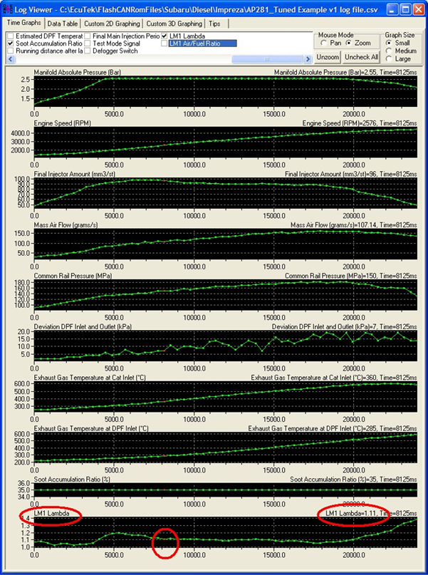
On the 4th gear road pull shown above Lambda is around 1.1 (16:1 AFR), this is the absolute minimum recommended value before visible Black smoke will appear. TAKE CARE with models fitted with DPF as Black Smoke will not be shown but the DPF will become blocked very quickly.
Always log the Soot Accumulation parameter in DeltaDash to avoid a blocked DPF.
We suggest Lambda 1.15 to 1.2 should be the lowest value seen. If Lambda is lower than 1 then reduce the Injection Quantity Amount.
Fuel Rail Pressure (MPa)
New Common Rail Diesel Engines use very high fuel pressure. Maximum Rail Pressure used is 180 MPa. There is a Mechanical Pressure relief valve on fuel rail used for safety, which is usually around 200MPa and will bleed fuel back to the tank should Fuel Pressure Increase above this. So do not demand over 200MPa or the Fuel Pump will be working very hard only for the fuel to be wasted back to the tank. Try to avoid increasing Fuel Pressure over the stock 180MPa. It is possible to achieve very good power and torque increases throughout the RPM range without having to change the Fuel Pressure maps.
Should you Increase the Target Fuel Pressure values below 180MPa, ensure these changes are applied to ALL Fuel Pressure Target tables.
A higher Fuel Pressure is a good and proven way of increasing power/torque output across the RPM range and Fuel Atomisation should (in theory) also be improved.
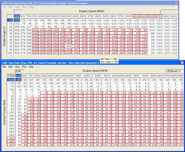
Max Injection Quantity
The output torque value from the MAXIMUM TORQUE limit maps is used in the Desired Torque value on the Y-axis of the MAX INJECTION QUANTITY map.
Be sure that you rescale the Y-axis to match nearer to your Desired Torque value.
Example: You can DESIRE 420NM but if the Y-axis on MAX INJECTION QUANTITY map is only scaled to 360NM then you will not have any more fuel quantity injected between 360NM and 420NM. By extending the Desired Torque values on the MAX INJECTION QUANTITY map’s Y-axis we will now inject more Fuel Quantity between 360NM and 400NM (in the example shown below).
NOTE: We suggest that you simply increase the Max Injection Quantity map by percentage.
Very good, easy and simple results can be achieved by adding 20% to actual Injection amount from 1200rpm to 5000rpm over 20NM of Torque Input. This simple modification will produce a good increase without altering any Torque maps at all.
Injector Opening Time
This map is a favourite map for most diesel tuners. The ECU calculates how much Fuel
Quantity in mm3 is required and for a given Fuel Pressure how long to keep the Injector open
(Injector Open Time in m/s) to delivery that Quantity of fuel in mm3. Simply Increasing the Opening Time in m/s by a percentage can work reasonably well. One downside (depending on your sales tactics) is any Fuel Consumption meter can become inaccurate due to the ECU not actually Injecting the Quantity of Fuel it actually calculated it injected! The fuel meter will show improved fuel consumption, though this would not actually be true.
Any DPF calculations for regeneration time periods could also be incorrect if based against actual Injection Quantity though this is unlikely to cause a problem as the pressure sensors in the exhaust should trigger a premature regen cycle anyway.
We suggest that you apply a percentage increase to the MAX INJECTION QUANTITY maps instead.
Smoke Limit
Smoke Limit table will limit the Maximum Injection Quantity amount during transient throttle conditions where the Lambda value will drop and cause Black Smoke. This happens particularly during turbo spool (Turbo Lag), so the Injection Quantity is restrained by the Smoke Limit tables against Boost Pressure or sometimes against Airflow (mg/cyl). The Smoke Limit Tables do not always limit Injection Quantity once the turbo has spooled and is on full boost pressure.
Limiters for Injection Quantity and Fuel pressure
These 2D maps limits the maximum amount of Injection Quantity allowed in mm3 or maximum allowed Fuel pressure in MPa.
Sensor Scaling
MAF Sensor scaling
This 2D map only needs adjusting if the Air Intake Tube, that contains the MAF sensor, is replaced for a larger housing. There is no need to adjust this otherwise.
Airflow
Increasing Power and Torque output with more fuel (Injection Quantity mm3) does not actually increase airflow, as seen with petrol engines where airflow can be related to power output. Diesel engines run continuously with a large excess air ratio.
Torque
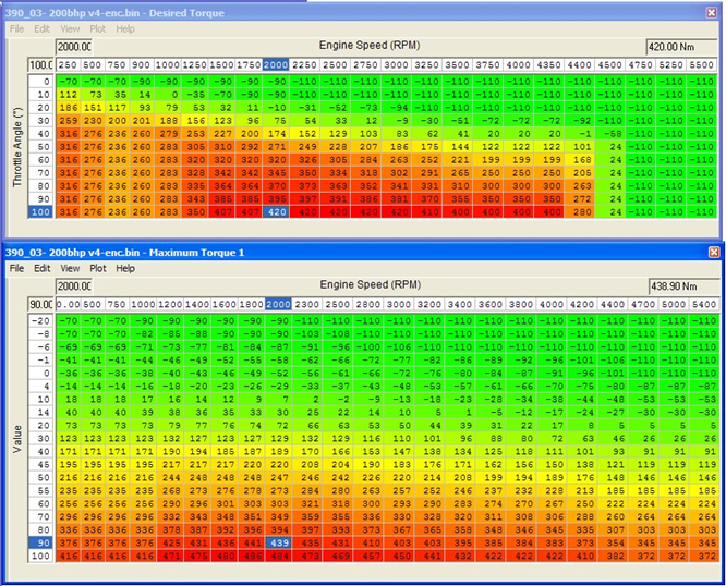
Desired Torque and Maximum Allowed Torque Limit
Desired Torque table can be used to increased torque output on part throttle.
If you Increase the torque value in the Desired Torque table then you may not actually achieve that higher Desired Torque Value due to the MAXIMUM TORQUE limit maps.
There are several MAXIMUM TORQUE maps, the ECU does swap between them for different vehicle speeds and conditions, so be sure to alter all MAXIMUM TORQUE maps by the same amount.
NOTE: Just because you desire 420NM does not necessarily mean the Maximum Torque Yaxis Input will be 100% of the Desired 420NM , many other factors like vehicle speed, Coolant Temp , Air Temp , Atmospheric Pressure and any learning or Torque Reduction tables may reduce the Desired Torque value proportionally.
In our experience the ECU normally uses around 90 to 95% of the Desired Torque assuming the engine is up to temperature and Air temperature is not too high.
Torque Reduction maps
There are various Torque reduction maps for air temp, coolant temp and vehicle speed (or Per Gear). Reduction from high coolant temp can stop the engine overheating whilst pulling a heavy load up a long steep hill. Per Gear maps are useful to reduce engine torque output in a low gear or in 4WD LOW where Engine Torque Output is multiplied to enormous values at the wheels, which could easily break gearboxes or differentials. Per Gear Torque reduction maps can also be used as a Vehicle Max Speed Limiter.
EcuTek ProECU tuning tools tools should only be used by experienced tuners who understand the product and engine calibration.
If you do not fully understand this product then you WILL damage your engine, ECU or your vehicle.
Please ensure you fully read all EcuTek manuals BEFORE attempting to use ProECU with your laptop or your vehicle.
Use with extreme caution and understanding at all times, if in doubt then do not proceed.
EcuTek accepts no responsibility for any damage to the engine, ECU or any part of the vehicle that results directly or indirectly from using the product.
** If you are in any doubt that you do NOT have the experience required to use this product then you should NOT USE IT **
Retail customers
** If you have any doubt that you do NOT have the experience required to use this product then you should NOT USE IT, you should simply contact your EcuTek Master Tuner shown clearly on the top of your Programming Kit or visit your preferred tuning shop to have a professional tuner use it for you **