VR30DDTT Fuel System
- Brandyn Mowat

ProECU Nissan/Infiniti VR30DDTT
v1.4
ProECU Tuning Manual Supplement: VR30DDTT Fuel System
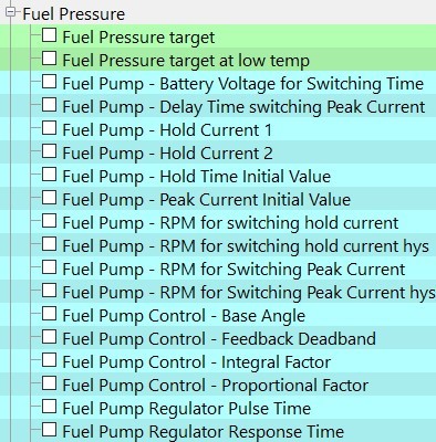
Fuel Pressure
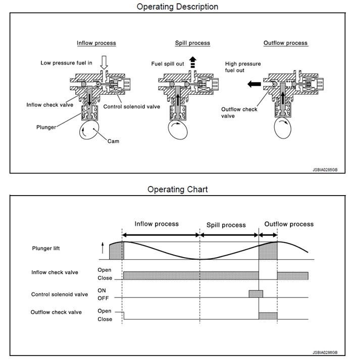
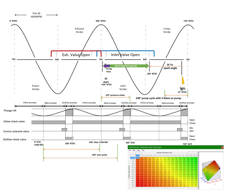
The fuel pump in a VR30DDTT is slightly different to other manufacturers but seems to be common across the Nissan DI engines. Nissan specify a trigger point at which to start the outflow process to deliver the correct amount of fuel volume to maintain the correct pressure. The pump works as below but the VR30DDTT has a 3 lobe fuel pump cam, this means that we have 240 degrees of crank rotation per pump cycle and 120 degrees for an output stroke.
The corrections for closed loop fuel pressure control are all modifiers to the outflow trigger angle. Below is a diagram illustrating how we believe that the pump control strategy and target maps work. The Fuel pump control - Base angle map is the ECU's initial point to trigger the outflow process. There are dead times, current targets and limits used as well, but these would only need to be changed if the pump solenoid is different, similar to what you would do if you were to change the injectors in other platforms.
The base angle maps give the start angle for the outflow process. The start angle (Fuel Pump Angle Target – Base) then has closed loop feedback corrections applied to it before the final value (Fuel Pump Angle Target) is used to trigger the solenoid. There are two closed loop feedback methods used and the directly work in degrees crank angle.
There are
- Proportional feedback (Fuel Pump Angle Target – Prop)
- Integral feedback (Fuel Pump Angle Target – Int)
It applies the correction coefficients to the calculated fuel pressure error like below.
Feedback Correction Angle = Map Output x (Fuel Pressure - Fuel Pressure Target)
The correction angle values are directly applied to the base output value. If you find your actual fuel pressure does not match the target fuel pressure the first step is to adjust the base map, for example.
- Increase the angle to decrease stroke and delivered pressure
- Decrease the angle to increase stroke and delivered pressure
If you find that the Fuel Pressure does not meet the Fuel Pressure Target you can modify the proportional and integral factor maps at the required RPM to smooth out the delivered pressure.
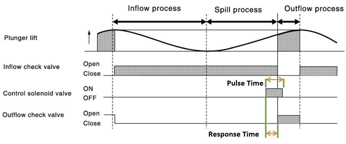
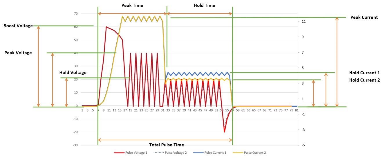
The fuel pump solenoid is controlled in a peak and hold method. If you are calibrating a replacement fuel pump solenoid it’s likely you will need to adjust Fuel Pump Regulator Pulse Time and Fuel Pump Regulator Response Time.
If only the mechanical pump unit has been changed, the Fuel Pump Control - Base angle and associated PID maps will require recalibration and the solenoid maps can be left alone. If changing the fuel pump solenoid you may need to alter the actual drive pulse characteristics to suit the physical changes to the solenoid, the drive current and voltage look a little like below, when changing the pulse characteristics use the below diagram as a reference.
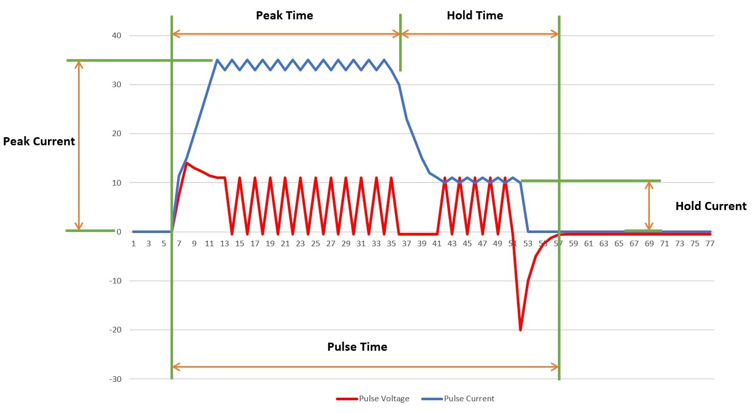
The time period for each total pulse is set by the fuel Pump Regulator - Pulse Time. The hold component is set by the Fuel Pump - Hold Time Initial Value and the peak section is the difference between the total and hold section of the drive current profile. Peak and hold current can also be switched to different levels depending on engine speed if required.
Map List
Live Data Parameters
- Fuel Pressure Target (Mpa) - Fuel Rail Pressure target
- Fuel Pressure (Mpa) - Actual Fuel Pressure in High pressure fuel rail
- Fuel Pressure Sensor (mV) - Fuel Pressure sensor raw voltage
- Fuel Pump Angle Target (°)– Actual target angle for fuel pump solenoid trigger
- Fuel Pump Angle Target - Base (°) – Base map angle output value
- Fuel Pump Angle Target – Int (°) – Current integral correction angle output value
- Fuel Pump Angle Target – Prop (°) – Current Proportional angle correction value
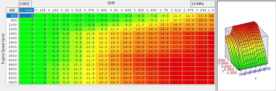
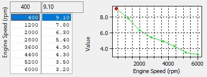
Fuel Pressure Target / Fuel Pressure Target at Low Temp
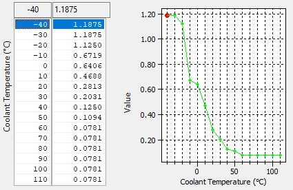
There are two fuel pressure target maps, these are active dependant on high and low coolant temperatures. The output is in MPa and profiled for specific RPM and QH0. This value is used for the error calculation and fuel pressure correction function.
Fuel Pump Control - Base Angle
This is the crank angle at which the trigger pulse for the fuel pump solenoid is set.
- Increasing the angle reduces outflow and pressure • Decreasing the angle increases outflow and pressure.
If the Fuel Pressure is not hitting the Fuel Pressure Target at the final Fuel Pump Angle Target displayed change this map to give more pump stroke to maintain pressure. Be aware that if the angle is set to high or low it will trigger the pump before on the inlet stroke and cause pressure issues.
Fuel Pump Control - Feedback Deadband
This is the pressure range in which the proportional and integral feedback of solenoid trigger angle will not become active. In the example if the error is outside of 0.5 Mpa, the P&I correction will commence.
Fuel Pump Control - Proportional Factor
This is the proportional gain used to calculate the instantaneous absolute addition to the Fuel Pump Target angle. Based on RPM, the feedback angle is generated using the fuel pressure error value multiplied by the proportional correction amount.
Fuel Pump Angle Target – Prop = Fuel Pump Control – Proportional Factor map output x (Fuel Pressure - Fuel Pressure Target)
Increasing the factor give more instantaneous correction for the same amount of fuel pressure error
Fuel Pump Control - Integral Factor
This is an integral gain factor map to calculate the cumulative addition to the Fuel Pump Angle Target. Based on RPM, the feedback angle is generated using the fuel pressure error value multiplied by the proportional correction amount at the loop speed.
Fuel Pump Angle Target – Int = Fuel Pump Control – Integral Factor map output x (Fuel Pressure - Fuel Pressure
Target)
Increasing the factor give more correction and faster responding cumulative values for the same amount of fuel pressure error.
Fuel Pump Regulator Response Time
This is the dead / lag time of the pressure control solenoid, when changing pump solenoids this must match the dead time of the new solenoid installed. Like injectors, if tuned incorrectly it will effect the closed loop pressure control systems.
Fuel Pump -Battery Switching Time
At different battery voltages the ECU uses different times for switching between hold time initial values of the fuel pump solenoid. Depending on what the battery voltage is, it will use the range specified on the Fuel Pump - Hold Time Initial Value map, see that map description for more details.
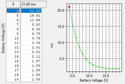
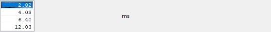
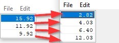
Fuel Pump - Hold Time Initial Value
When the battery voltage is above the top threshold of Fuel Pump – Battery Voltage switching Time the top row of this map is used, when between the top and middle threshold the second values are used, as per the second image.
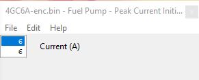
Fuel Pump - Peak Current Initial Value
The target current (Amps) for the Peak driving phase of the pressure control solenoid. This could be adjusted to better suit increased current demands of an upgraded pump solenoid. The two values are for mode 1 and 2 as per the hold current maps and its believed these are switched by exceeding the thresholds Fuel Pump - RPM For switching Peak Current & Hys.
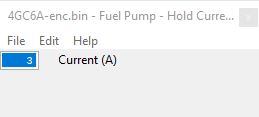
Fuel Pump - Hold Current 1 & Fuel Pump - Hold Current 2
Target hold current set to drive the pressure control solenoid. Two maps are used for different modes but believed they are switched at the engine speed determined at Fuel Pump - RPM for switching Hold Current. This could be used to cope wit hthe increased current demands of an upgraded pump solenoid.
Fuel Pump - RPM for switching Hold Current
RPM level at which the ECU changes from using the Fuel Pump - Hold Current 1 to Fuel Pump - Hold Current 2

Fuel Pump - RPM for switching Hold Hysteresis
Hysteresis value used when the RPM for switching hold current is reached.

Fuel Pump RPM for switching Peak Current
RPM at which the ecu changes from using Fuel Pump - Peak Current 1 to Fuel Pump - Peak Current 2
Fuel Pump RPM for switching Peak Hysteresis
Hysteresis value used when the RPM for switching peak current is reached.
Fuel Pump - Delay Time Switching Peak Current
The peak current drive for the control solenoid on the fuel pump.
Fueling (Target & Control)
Map List
Live Data Parameters
- AFR Average (AFR) – Bank 1 and 2 sensor values averaged
- AFR Average Calibrated (AFR) – Bank 1 and 2 sensor output using EcuTek Polynomial averaged
- AFR Bank 1 (AFR) – Bank 1 O2 sensor output as seen by the ECM
- AFR Bank 2 (AFR) – Bank 2 O2 sensor output as seen by the ECM
- AFR Bank 1 Calibrated (AFR) – Bank 1 O2 sensor output as seen by the EcuTek Polynomial
- AFR Bank 2 Calibrated (AFR) – Bank 2 O2 sensor output as seen by the EcuTek Polynomial
- AFR Sensor B1 (V) – Bank 1 O2 sensor output raw voltage
- AFR Sensor B2 (V) – Bank 2 O2 sensor output raw voltage
- AFR Sensor Heater #1 (%) – Percentage duty of Bank 1 O2 sensor heater
- AFR Sensor Heater #2 (%) – Percentage duty of Bank 2 O2 sensor heater
- AFR Target B1 (AFR) – Bank 1 target AFR
- AFR Target B2 (AFR) – Bank 2 target AFR
- Fuel Injection Angle (°)– OEM injection angle parameter
- Fuel Injector Duration B1(ms) – Injector open time on bank 1
- Fuel Injector Duration B2 (ms) – Injector open time on bank 2
- Fuel Injector End to Spark (ms) – Time between end of injection and ignition event.
- Fuel Trim Long term B1 (%) – Percentage extra injector open time applied by long term fuel correction
- Fuel Trim Long term B2 (%) – Percentage extra injector open time applied by long term fuel correction
- Fuel Trim Short term B1 (%) – Percentage extra injector open time applied by short term fuel correction
- Fuel Trim Short term B2 (%) – Percentage extra injector open time applied by short term fuel correction
- Injector Open Time (ms) – The injector open time of the last pulse used in the sequence
- Map Trace AFR (AFR) – Value used to map trace on fuel maps and ignition maps when colouring by AFR
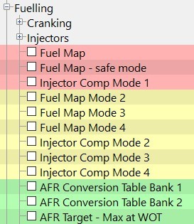
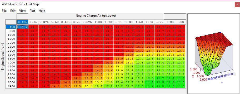
Fuel Map Mode 1-4
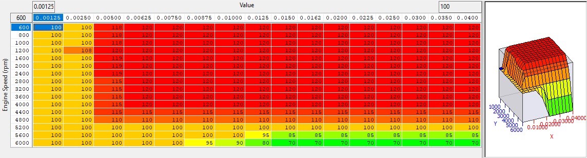
This is the target AFR the ECU employs when not in lambda control modes. There are individual maps for each mode 1-4. These maps are equivalence ratio shown as AFR by the map editor. Each mode 1-4 applies to the relevant switchable map.
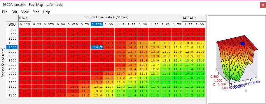
Fuel Map - Safe Mode
There is a safe mode map as well that we believe is used when the car senses knock events or suspect the octane rating of the fuel has changed (For example after refueling)
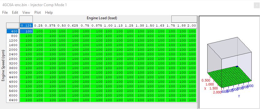
Injector Comp (Mode 1-4)
The injector compensation maps work directly on the injector magnification values and as such directly effect injector open time during engine operation. They are load and RPM scaled and as such can be used to adjust the total fueling under certain running conditions or compensate "Per Mode" for different fuel densities and mass flow rates e.g. Ethanol Fuels.
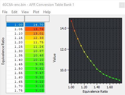
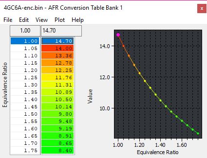
AFR Conversion Bank 1 & 2
There are many different OEM fuelling target selection modes, these are for functions used when trying to achieve high efficiency closed loop stoichiometric fuelling, low temperature cat warm up, limp modes and High Load running conditions. The AFR conversion tables are an offset adjustment to the output of the fuel maps (in equivalence ratio) to convert into AFR. While the exact reason for having a changeable Eq ratio to AFR conversion is unknown we suspect it is to do with “in cylinder mixing” or safety factors.
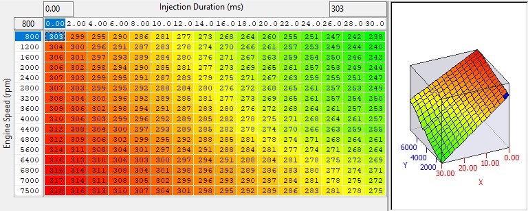
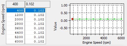
These two maps, one for each bank, are used internally by the ECU to convert values in the main fuel map to bank specific AFR targets. The units are Equivalence Ratio and can be converted to AFR by dividing 14.7 by the values in the table, for example 1.00 gives an AFR of 14.7:1 and 1.336 gives an AFR of 11:1.
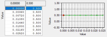
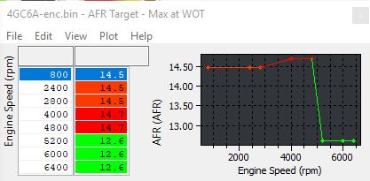
By default they do not give an output identical to the input, and it is different between each bank, and they typically translate values from the fuel maps at high load to slightly richer targets. To nullify this effect, set that the data values to exactly equal the input values, but be aware that the result is that the reported AFR target and AFR logging parameter will not match when long and short term fuel trims are 100 (no trimming).
This ends up with a setting that looks like the second image.
AFR Target - Max at WOT
This is the leanest AFR Target permitted for a given RPM when at WOT. It could also be called "Leanest AFR for Best Torque." Of the values returned by this map and the main 3d fuel maps, the richest value will be used by the ECU. Raising the values in this map prevents rich AFR Targets from interfering with the intended target AFR typically used on high power cars with modified exhaust systems. Setting all the values in this map to 14.7 will completely disable the effect.
Cranking
There are many cranking maps and this function is not well understood at this time. There are set pulse widths for cranking phases with references to coolant temperature as well as after-start enrichment periods.
There are 4 pulse modes and 3 injection windows, these injection modes relate to which windows are used, the 4 modes are
- Homogeneous Middle Pulse Mode
- Homogeneous Pulse Mode
- Stratified Pulse Mode
- Pre-Injection Pulse Mode
The 3 windows that are used are an early, a middle, and a late window, and these have different start and end angles set in the software. The modes and windows are all decided “per injector” sequentially.
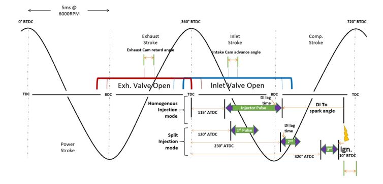
Fuel injection timing (injection Angle 1, 2 & 3 in deg) Indicates the fuel injection timing computed by the ECM according to the input signals. There are 3 windows for injection events and it has been seen that at low RPM and peak torque these different windows are used mostly. This is to improve emissions and mitigate low speed preignition events that can occur. When using Homogenous injection strategies Injection Angle 2 is used mostly,
NOTE: Injection Angle indicates degree of start of injection from TDC of intake stroke (After Top Dead Center). The diagram below shows the relationship between injection angle and combustion cycle.
Map List
These tables will be released in the near future though the names may change.
Live Data
- Injection Pulsewidth 1 Cylinder 1-6 - The injection timing of pulsewidth 1 in milliseconds for each cylinder
- Injection Pulsewidth 2 Cylinder 1-6 - The injection timing of pulsewidth 2 in milliseconds for each cylinder
- Injection Pulsewidth 3 cylinder 1-6 - The Injection timing of pulsewidth 3 in milliconds for each cylinder
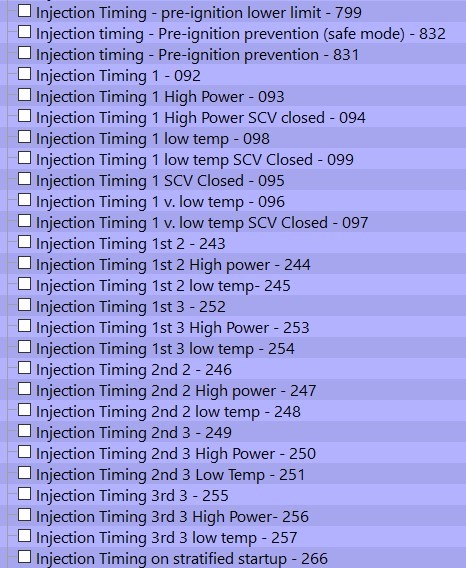
As described in the introduction, the injection timing maps set the angle after TDC of exhaust/intake stroke. The output values are in crank degrees and they are set by engine speed and a calculated load condition using multiple variables to generate the output value.
There are many different modes in which different injection windows are used and different injector “start of pulse” angles are chosen, these are for High power low temperature or SCV position.
Injector Characteristics
Direct injection (DI) characteristics are quite complex but can be broken down into several controlling functions. The injectors are driven at a high voltage for a short time using the high-pressure fuel supply to achieve the required quantity in a short period. The ECM is equipped with an injector driver unit that drives the fuel injector at approximately 65 V (maximum) to increase the speed of injector opening thus increasing the operating window available.
Injector characteristics are split into pressure groups like the following.
- High Pressure failure (pressure to high)
- High pressure
- Normal pressure
- Low Pressure
Each pressure mode has its own set of injector characteristic maps (including peak and hold currents, switching times and delays). The opening time is calculated using these values which are further split into the phase of the injector driving cycle. There are 2 main phases, a peak current phase to drive the injector open and a hold current phase to keep it open. The final pulse width is subject to low pulse width linearization maps and minimum open times
Injector Magnification
The injector flow differs at different fuel pressures. To compensate for this, the response time of the injector can be modified for fuel pressure using the Injector Magnification map.
- Increasing the value will increase the calculated fuel amount required.
- Decreasing the values will decrease the amount of fuel calculated for the current conditions.
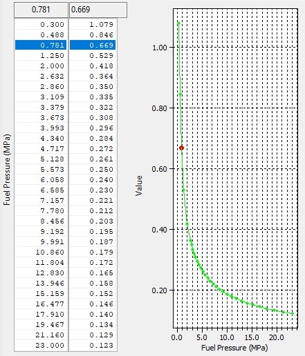
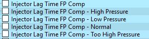
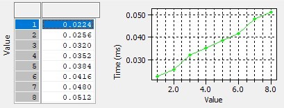
Injector Lag Time FP Compensation
The axis of this map is fuel pressure and the output in milliseconds. These are added to the 0ms base time in order to form a lag time value.
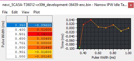
Injector Narrow Pulse-width Linearization Compensation
Direct injectors do have a non-linearity characteristic much like port injectors. The low pulse width linearization maps are split into fuel rail pressure modes and injector drive current phases.
The chart to the side explains the map functions, they should only need to be adjusted if aftermarket injectors are fitted.
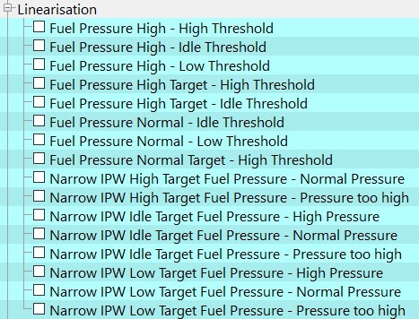
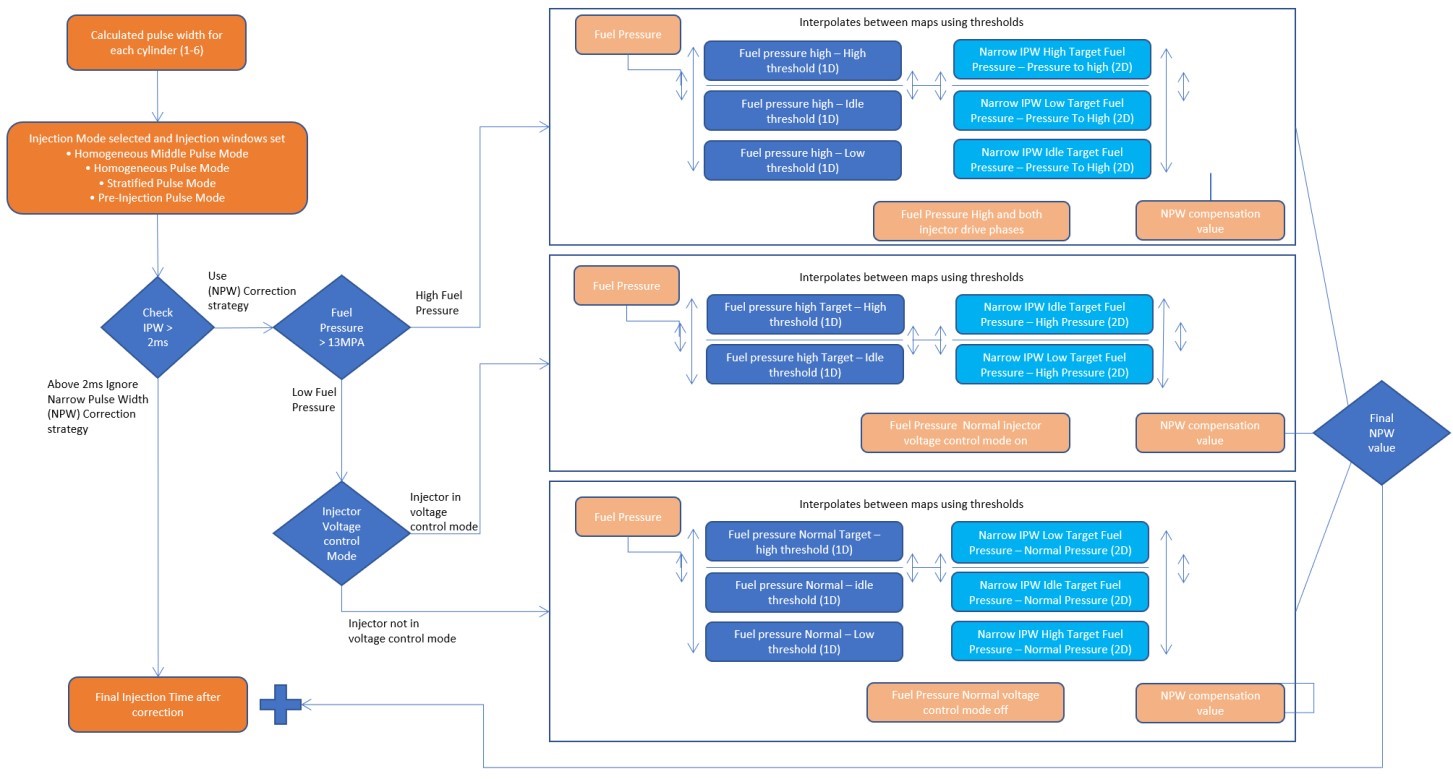
Fuel Pressure High Target - Idle Threshold (1D)
These 1D values are used to interpolate other values. They are compared to the current fuel pressure value and the difference between the respective threshold values. The difference sets the interpolation factor between the 2D narrow IPW Target Fuel Pressure -Pressure maps as per the diagram above. These values will not need to be changed unless the injectors have beeen upgraded. The injector supplier should give these values if required.
These tables and the similar tables use the interpolation amounts of the 1D pressure thresholds to set the desired addition to pulse width. There are 2 or three maps per mode shown in the diagram above. They have initial injector open time as the input and output a value to add to this current injector time. These values will not need to be changed unless the injectors have been upgraded, the injector supplier should give changes to these values if required.
Injector Current Characterisation
The injectors are driven in a peak and hold fashion per fuel pressure mode, there are individual times currents and delays involved for each of these modes, the modes are
- High Pressure Failure
- High Pressure
- Normal Pressure
- Low Pressure
The current drive pattern is the same as most other injector drivers and is roughly represented to the left.
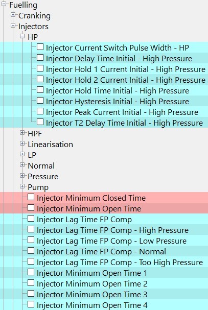
The pressure mode map list consists of the maps below, there is a tree for each pressure mode.
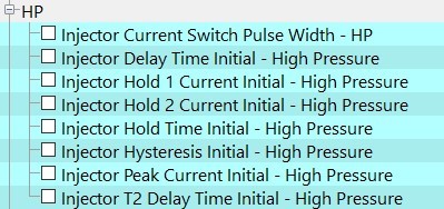
Pressure Threshold
Threshold for fuel pressure being too high, when this value is achieved the fuel pump current is adjusted.

Injector Current Switch Pulse Width
Initial Peak time switch point where the injector drive switches from peak to hold mode.

Injector Delay Time Initial
Initial delay timer for the total pulse to start

Injector Hold 1 Current Initial
The target hold current for injection mode 1

Injector Hold 2 Current Initial
The target hold current for injection mode 2

Injector Hold Time Initial
The initial time of the hold current phase. If the total pulse duration isn't long enough, hold pulse won't be used.

Injector Hysteresis Initial
The target peak current during the peak drive phase.

Injector Peak Current Initial
Hold delay time for injector mode 2.

Injector T2 Delay Time Initial
Hold delay time for injection mode 2