VR30DDTT Ignition Timing
- Brandyn Mowat

ProECU Nissan/Infiniti VR30DDTT
v1.4
ProECU Tuning Manual Supplement: VR30DDTT Ignition Timing
Introduction
The OEM ignition timing strategy works very well when applied to a stock car. However when moving on to a high power application, it can be difficult to work with and restrictive. RaceROM adds easy to use larger maps that boast a high precision load input axis for improved control and range. Additional supporting maps were also added for further safety.
The VR30DDTT platform uses a maximum Best Torque (MBT) timing ma, a base map (knock limited) and an ignition timing maximum allowed map to determine the base timing. It will choose the lowest value of the Base MBT or Max map and then apply the engine condition corrections and the knock detection correction amounts.
There is a safe mode (low octane) map that can be switched to if the car enters limp mode (From DTC's) or high knock levels have been sustained for a set period. The safe mode can sometimes be enabled if the vehicle is refueled but that is yet to be confirmed. The diagram below illustrates the basic control functions and major inputs however there are additional maps and parameters that go in to the system.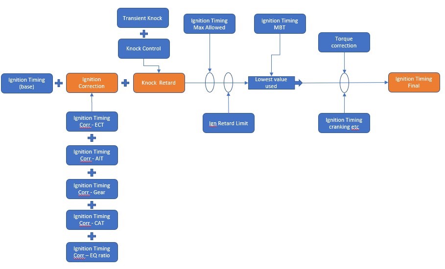
Table of Contents
Live Data Parameters
- Ignition Timing Base (°) – Current base ignition timing in degrees BTDC, negative means ATDC
- Ignition Timing Base lookup (°) – Current ignition timing map output in degrees BTDC, negative means ATDC
- Ignition Charge air correction (°) – Current ignition timing correction for CAT degrees
- Ignition Final (°) – Current actual ignition timing in degrees BTDC, negative means ATDC
- Ignition MBT (°) – Calculated MBT ignition timing in degrees BTDC for use in Torque Calcs and max Limits
- Ignition Timing (°) – Current actual ignition timing in degrees BTDC, negative means ATDC
- Ignition Timing Correction (°) – Ignition timing correction amount
- Knock Retard (°) – Offset due to knock, negative is retard, positive is dynamic advance on GEN 2
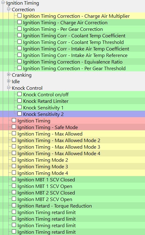
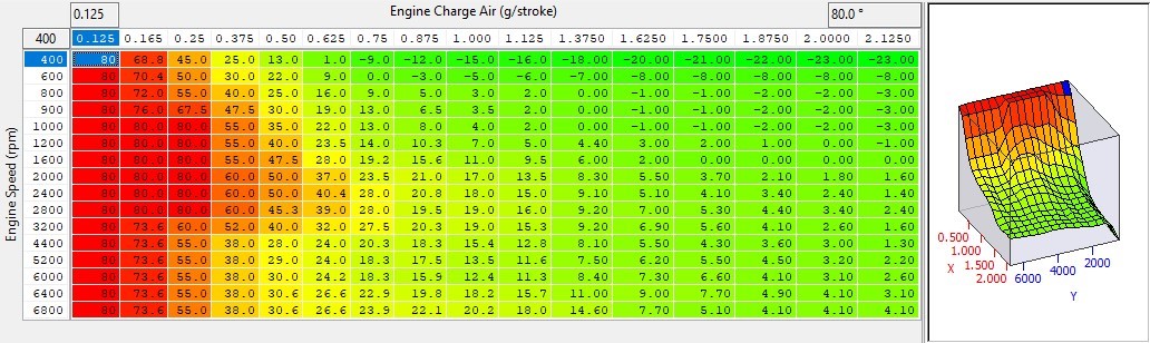
Ignition Timing Mode1 (Mode2, Mode3, Mode4)
Four maps, one for each mapswitch mode providing an easy to understand and tune base ignition value in degrees BTDC. They provide increased precision and headroom for the load axis and increased RPM breakpoints. It's possible to create multiple maps and use map switching to cycle between each map for testing.
The numbers in these maps may not equal the final timing value as it will be subject to RaceROM corrections, knock control, dynamic advance and other OEM timing corrections.
These maps are not employed in overrun and idle conditions where the OEM ignition control is used.
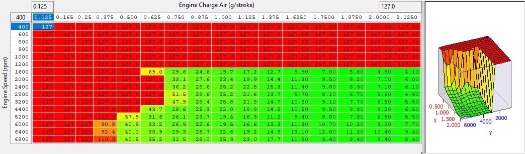
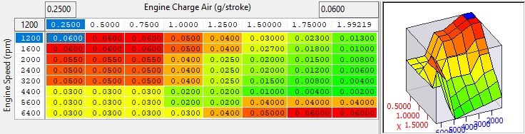
Ignition Timing - Max Allowed Mode1 (Mode2, Mode3, Mode4)
This is the max allowed ignition timing. It is applied after the base map and corrections but before the torque reduction functions. It will cap the amount of corrections that can be applied ensuring sensible ignition values if sensors are misread.
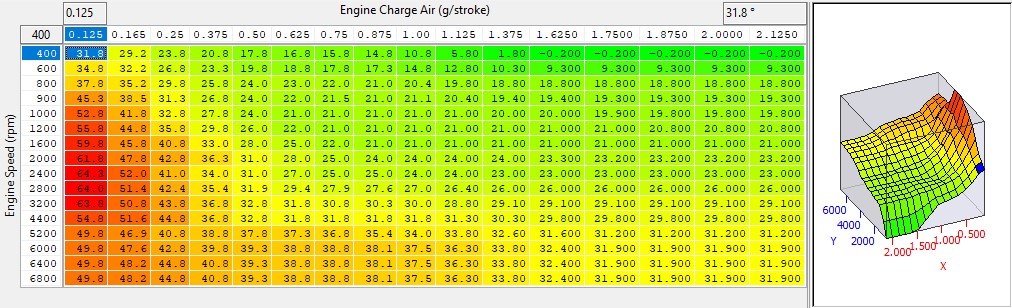
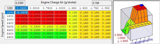
Ignition Timing MBT (1, 2, SCV Open & SCV Closed)
This is the calibrated Maximum Best Torque (MBT) timing for the engine in it's OEM form. The timing will be limited to this value if the requested timing above this. You should not need to go above this timing value.
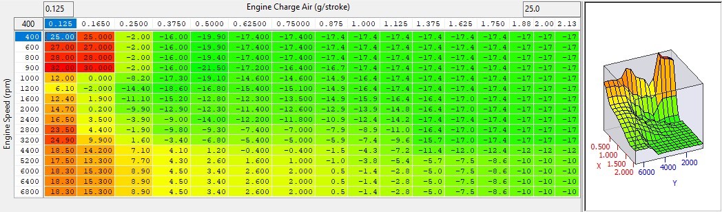
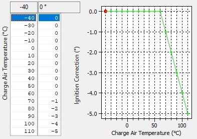
Ignition Timing - Charge Air Correction
Ignition advance can be trimmed for increased charge air temperature using this map
Ignition Timing Correction - Charge Air Multiplier
Ignition Timing Correction - Charge Air Correction can be modified relative to RPM and engine load using this map. It would be normal to reduce ignition advance in higher gears at high RPM or at an RPM sensitive to detonation.
Ignition Timing Corr - Coolant Temp Coefficient
An ignition timing offset based on the difference between coolant temperature and Ignition TIming Corr - Coolant Temp Threshold. This can be used in order to retard or advance the ignition timing for different coolant temperatures. The final correction amount due to coolant temperature is calculated using the following formula.
Coolant Temp Correction amount = (ECT Threshold - Current ECT) x Coolant Temp Coefficient
Ignition TIming Corr - Coolant Temp Threshold
This is the value used in the formula to calculate the "difference" value that is multiplied by the RPM and the load scale map Ignition TIming Corr-Coolant Temp Coefficient

Ignition Timing Corr - Intake Air Temp Coefficient
A modifier for ignition timing offset based on the difference between Intake Air Temperature and Ignition TIming Corr - Intake Air Temp Reference and can be used to retard or advance the ignition for different intake air temperatures. The final correction amount due to IAT is calculated using the following formula.
IAT Correction Amount = (IAT Reference - Current IAT) x IAT Temp Coefficient
Ignition Timing Corr - Equivalence Ratio
This map multiplies the difference between lambda 1 and the current lambda value and adds this to the correction calculations.
EQRatio Correction Amount = (𝜆Stoich - 𝜆Current) x Equivalence Ratio Corr Map Output
Ignition Timing Corr - Per Gear Threshold
The load value (g/stroke) at which per gear corrections become active

Ignition Timing - Per Gear Correction
An amount of ignition retard (or addition) that is applied dependant on current gear and RPM. It is only applied after the load threshold has been exceeded. This can be used to compensate for the increased loading and heat generated in higher gears/high speed.
Knock Control
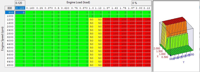
Knock Control On/Off
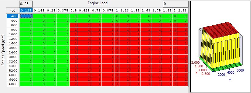
This is an easy to use enable (1) or disable (0) map based on laod and RPM for application of knock based timing retard as calculated by the knock control strategy.
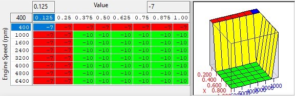
Knock Retard Limiter
Limit applied to the amount of retard that is able to be set by the knock control strategy. Based on engine load and RPM and outputting in degrees of ignition timing. This can be used to limit or increase the amount of knock ignition retard allowed.
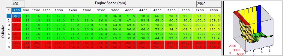
Knock Retard Sensitivity 1
This per-cylinder threshold map is the point where knock correction will become active for each cylinder. If the values against RPM are breached, then the knock correction parameter will start to show knock retard. Built engines often generate excessive engine noise that can be detected as knock. Raising these values will help prevent this being detected, though care must be taken that the sensitivity will still show true knock! The centre wo cylinders tend to show more noise due to cylinders on either side, so the noise threshold are higher.
The logging rate per cylinder knock output cannot capture all knock events so proceed with caution!
Ignition Timing - Torque Reduction
This is the amount of retard (in degrees) applied for a given torque reduction percentage. Requests from other control functions such as limit modes or commands from other modules like the TCM, ABS or Stability Control Module.
Ignition Timing Retard Limit
This is the minimum achievable timing after al the corrections are applied. If you need to apply greater amounts of retard for torque control or shift torque reduction, adjust these maps.