VR30DDTT Boost Control
- Brandyn Mowat
- Lucan Hetherington

ProECU Nissan/Infiniti VR30DDTT
v1.4
ProECU Tuning Manual Supplement: VR30DDTT Boost Control
Introduction
As the VR30 utilises electronic wastegates it is possible to set WG position at any RPM, the principles (proportional, integral and derivative) are the same as a pneumatic wastegate, however the control is performed in position rather than duty. There are also turbo speed sensors in the 400hp (high boost pressure) model which adds another dimension to the amount of control the ECU can exert. There are no blow off valves (BOV) as standard equipment on the VR30DDTT motors and as a result they are susceptible to pre-throttle over-boost during gearshifts or when entering overrun. We have added some functionality to the boost control system in order to reduce the over boost amount, fortunately the system additionally is able to control MAP is relatively well using the throttle, further reducing the risk to engine internals.
Starting with RaceROM Version 3, the OEM boost control has been rewritten and replaced with our own simplified boost control strategy using its own set of dedicated RaceROM maps. Upon adding a version 3 or later RRFF, this option is enabled by default, and comes pre-populated with a sensible stage 1 boost control setup. 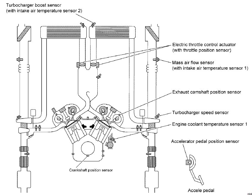
Table of Contents
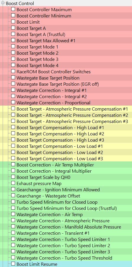
Map List
Live Data Parameters
- Boost Bank1/Boost Bank2 – Absolute pressure in bar, measured by the two boost sensors
- RBC Maximum Desired Boost – Relative boost max target, matches number format on gauge
- Boost Target – Absolute pressure target in bar, measured by the intake manifold pressure sensor Boost Error – Difference between MAP and Boost Target, positive numbers are over boost
- Boost Target – RBC Maximum – The current RR boost controller setpoint.
- Boost Target Multiplier – The QH0 based multiplier used for boost target correction
- Manifold Gauge Pressure – “Boost” pressure measured in bar above the current atmospheric pressure
- Manifold Absolute Pressure – Absolute pressure in bar, measured by the intake manifold pressure sensor
- Manifold Pressure Sensor – MAP sensor voltage value
- Turbo Speed B1 & B2– Current turbo speed in rpm only available on the 400hp models
- Wastegate Actuator Position B1 & B2 – The mm distance the wastegate has extended (related to WG angle)
- WG Actuator Position Sensor B1 & B2 – the WG position sensors current voltage output
- WG Corr Base – Output from Wastegate Posn. Corr. Calculation, not used in RR boost control strategy
- WG Corr Integral – WG duty added by Integral correction of EcuTek boost control strategy
- WG Corr Proportional – WG duty added by Proportional correction of EcuTek boost control strategy
- WG Corr - Prop Int Sum – Correction resulting from proportional and integral added together
- WG Corr – Transient – Derivative component of boost error calculation
- WG Offset – During Gearshift – Offset applied in mm during upshift.
- WG Target – Air Temp Comp – Air temp correction value from target map (in Bar)
- WG Target – Atmospheric Pressure Correction amount applied from the Atmo Pressure Comp map
- WG target – Basemap Lookup - the value referenced in the WG target map (in mm)
- WG Target – Position – Final Position target after all corrections (in mm)
EcuTek Boost Control vs RaceROM Boost Controller
There may be some confusion between the features for boost control in recent RaceROM versions, despite the similar naming due to historic reasons the two RaceROM features have different functions.
EcuTek Boost Control
EcuTek Boost Control is the control strategy to set the boost target and control the wastegate solenoid such that the boost reaches and remains on target.
RaceROM Boost Controller
(abbreviated to RBC) is a feature used to limit the boost target using ECU Connect and cruise control switchgear (when made available). The maximum boost target is displayed only in ECU connect or a ProECU log file. As can be determined from the boost target flow diagram the boost target can be below the value set by the RBC but it can never exceed it.
The RRBC is a final limit to any boost target, any boost target higher than the RRBC limit will be capped to the RRBC limit.
Note: If you are tuning on the dyno and not using ECU Connect to raise and lower the boost target set the Default and Max values to the same as your desired boost to avoid capping the target unintentionally.
RaceROM Boost Controller Default
Default value for adjustment of the RR boost controller value, this is used after programming or after battery reset etc.

RaceROM Boost Controller Maximum
Maximum limit for adjustment of the RR boost controller value, this is shown in ECU connect as well.

RaceROM Boost Controller Minimum
Minimum limit for adjustment of the RR boost controller value, this is shown in ECU connect as well.

Absolute Boost
As per the latest updates to GTR the VR30DDTT follows the use of Manifold Absolute Pressure (MAP) for all aspects of tuning the boost control. All boost target, boost limit and boost threshold values are all absolute values in Bar. Tuners will now find that all boost related maps and live data will give consistent readings regardless of altitude, and calculations will hold true in all circumstances.
To make tuning as simple as possible we have added the Boost Target - Atmospheric Pressure Compensation maps by default, this gives a consistent “boost” at all altitudes, but the result is that your MAP will drop as a result, and power will be reduced at altitude if using the default Boost Target Atmospheric Compensation map
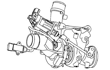
The VR30DDTT uses the latest technology for controlling the opening angle of the wastegates, the wastegate actuator is now electronically driven as opposed to pneumatically. The electric wastegate control actuator operates based on a signal from ECM and adjusts the turbocharger boost control valve angle via link rod. The electronic control allows the turbocharger wastegate control valve to be opened even in non-supercharging regions. This reduces pumping losses and contributes to the fuel economy. When boost is requested the wastegate valve angles are controlled by the electronic control with a high degree of accuracy but are currently limited to OEM WG setups.
The Key Principle with Electronic wastegates is that they are controlled by a target position as opposed to a duty cycle. This extension is
- 8mm equals fully extended / fully open wastegate (no boost)
- 0mm equals fully protracted / fully closed wastegate (full boost)
There is a further lower level control for the actuator but these are not required currently as aftermarket WG controllers are not widely available.
Enable Special Features (Boost Control Related)
EcuTek Boost Control – Enabled by default when adding RaceROM Feature File (patch)
The overall enable for the RaceROM boost control strategy is set by default when adding a patch. Once the patch is added the RR maps for boost control are used as opposed to the OEM strategy, this cannot be disabled or unchecked.
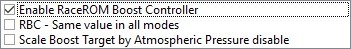
Enable RaceROM Boost Controller
Overall enable for the RBC, enabled by default. If turned off the cruise switchgear will do nothing boost control related.
RBC – Same value in all modes
Forces the RBC setpoint to be maintained even when switching MapSwitch Mode. There is a limitation of this in that ALL modes will have a maximum setpoint corresponding to the lowest of the four values in Boost Controller Maximum.
Scale Boost Target by Atmospheric Pressure disable
Forces the RRBC to ignore changes in atmospheric pressure when calculating boost error.
Boost Limit (Fuel Cut)
The manifold absolute pressure needs to exceed this limit, measured in Bar (Absolute) by the manifold pressure sensor, for a time that exceeds a currently undiscovered delay timer.
Boost Limit Resume
There are separate cut and resume maps to introduce hysteresis into the fuel cut.
With the default limit of 2.44 Bar (at 4400RPM) and a Resume of 1.86Bar, the fuel will be cut when the MAP exceeds 2.44Bar for a set time and resume when the MAP drops below 1.86Bar.
Boost Target
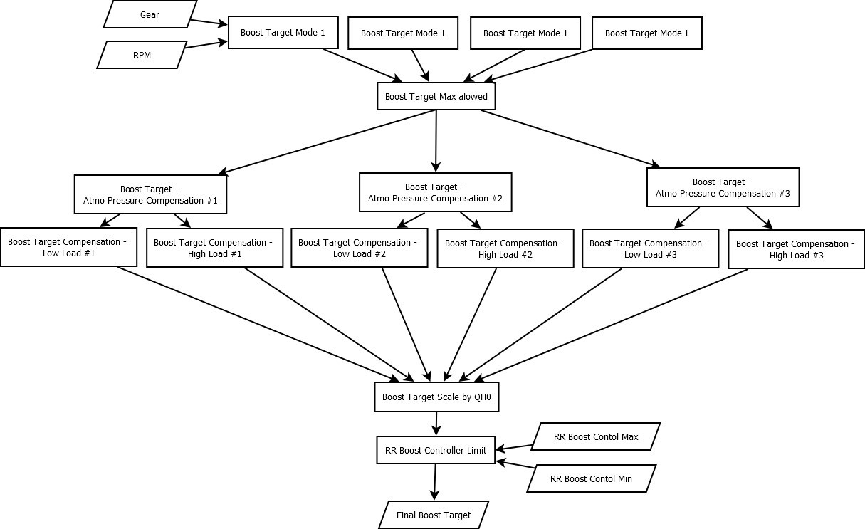
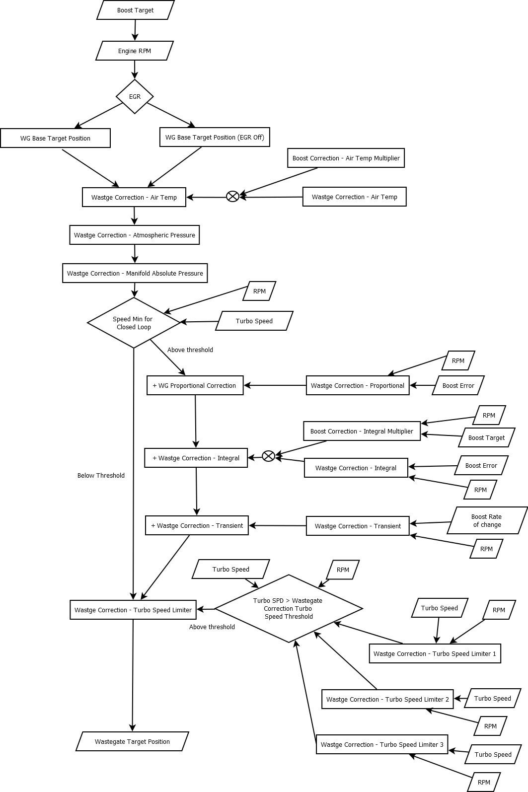
The boost target system in the VR30 product has some aspects that are slightly different to the normal boost target set point methods. The current understanding and setup can be seen in the below flow chart.
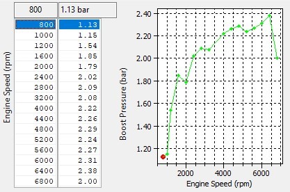
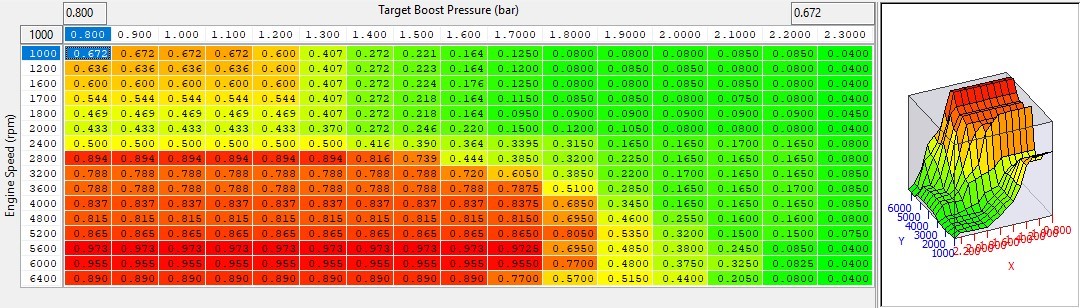
Boost Target Mode 1-3
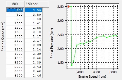
Boost target is now defined using four 3D maps with RPM and gear axis’, there are 4 separate target maps, one for each Map Switch Mode, throttle modulation is in the form of a simple 2D QH0 map.
An RPM dependant target boost profile is set on a per gear basis. Typically gears 1 and 2 have noticeably lower targets due to traction limitations
Boost Target Atmospheric Compensation
The boost target can be offset for changes in atmospheric pressure, the default map values reduce the absolute boost target 0.1Bar for the first 0.1 Bar drop in atmospheric pressure and stay at that afterwards. This is suitable for stock turbos which will often be further limited by turbo speed, pushing the same absolute pressure at altitude can be damaging to the turbos while still not achieving the desired pressure.
If working with turbos that have plenty of headroom at sea level then flattening this map to 0 will give the same absolute pressure target at altitude and result in similar power levels.
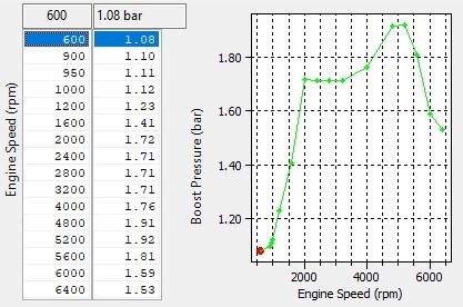
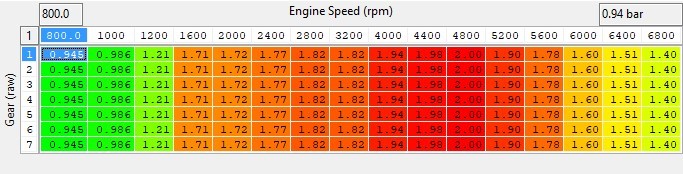
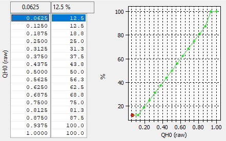
Boost Target Scale By QH0
The boost target as set by the Boost Target map is multiplied by the output of this map. For example, a target of 2.4bar * 0.45 = 1.08bar absolute.
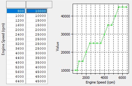
Boost Target Max Allowed
Maximum target based on engine speed, used as a maximum limit for boost target
Wastegate Duty Calculation
The Wastegate position calculation follows the process below, the closed loop control consists of a base wastegate position. The base duty is always subject to air temperature, Barometric pressure and Manifold pressure corrections. If the turbo speed is high enough (above he threshold for closed loop turbo control) a proportional, integral and a transient correction term are calculated and added. There is an overall turbo speed limiting waste gate correction amount applied when above the maximum allowed turbo speed threshold.
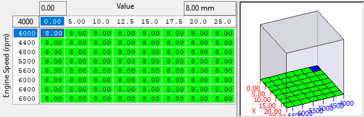
WG Base Target Position (EGR On) WG Base Target Position (EGR Off)
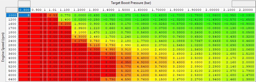
These two maps are used to set a base wastegate position for EGR On and EGR Off, which set a base position in mm extension for the WG for corrections. The X axis is target boost in Bar (absolute) and the Y axis is engine speed. 8mm = fully open, 0mm = fully closed. Negative values cannot be achieved but keep the profile of the map for OEM calculations.
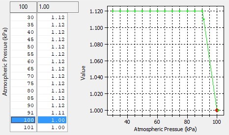
Wastegate Correction - Atmospheric Correction
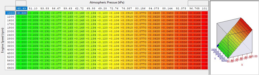
This map defines the amount of WG correction applied in millimeters to the base duty maps depending on the measured barometric pressure (in kPa).
Wastegate Correction - Air Temp
This map defines the amount of WG correction applied in millimeters to the base position maps depending on intake air temperature. The map output is then multiplied by the Boost Correction – Air Temp Multiplier.
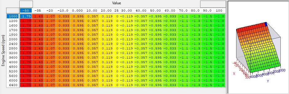
Boost Correction - Air Temp Multiplier
This map multiplies the amount of WG correction - Air Temp map output. The resulting output is then added to the base position map. It can be used to calibrate the wastegate - Air Temp correction map for a given RPM and manifold absolute pressure.
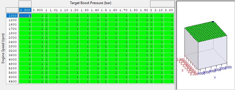
Wastegate Correction - Manifold Absolute Pressure
This map multiplies the output of all correction maps before the information is fed into the closed loop corrections.
Turbo Speed Minimum for Closed Loop & Trustful
A threshold of turbo speed to enable closed loop control of the wastegate position. Proportional, Integral and Derivative feedback are activated when the turbo speed value is exceeded and remains active until the turbo speed drops by an unknown hysteresis value. This table can be used to stop integral windup when at full throttle and waiting for the boost to rise.
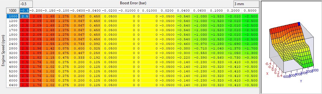
Waste Correction - Proportional
Proportional correction is absolute wastegate duty added or subtracted at an instant in time based on the current boost error. The default maps have high positive values when the boost is under target at low RPM while in spool up. Using high proportional values is preferable to high integral values to prevent windup but still results in low wastegate position on spool.
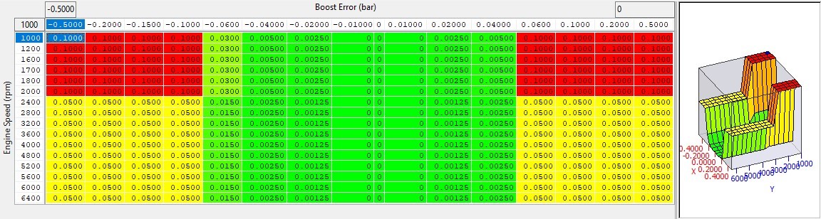
Wastegate Correction Integral #1 
Wastegate integral correction builds up over time. While active (See above conditions) this map dictates how much the integral value is increased with each cycle of the boost control loop. Each loop takes just 10ms (one 1/100 of a second) and the current integral correction is multiplied by the integral multiplier before being applied. It can be observed by checking the WG Corr - Integral live data parameter which is logged by default.
Boost Correction Integral Multiplier
Multiplies the current integral correction, the result is shown as the logging parameter called WG Corr – Integral. The intent of this map is to reduce or increase the effectiveness of the total integral correction based on engine speed and Manifold Absolute Pressure allowing fine control in different running conditions
Waste Correction - Transient (Derivative)
Transient/Derivative correction is absolute wastegate duty added or subtracted at an instant in time based on the current rate of change in boost. The default maps only have positive values when the boost is increasing at a fast rate (peak spool RPM). Using high derivative values should only really be needed to prevent the inertia of large turbos overshooting the boost target value but still need a closed WG position to spool.
![]()
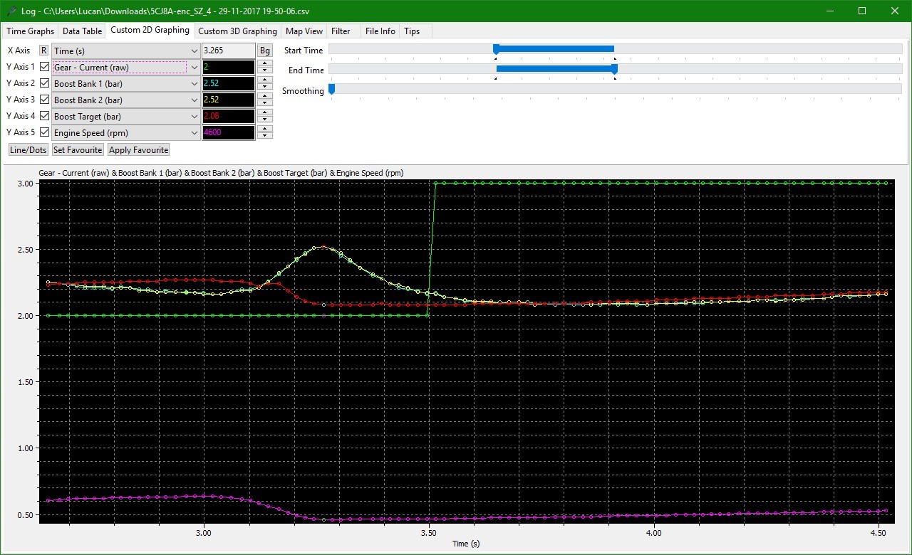
Gearchange Boost Spikes
The Turbo chargers on the VR30DDTT engines are designed for optimal drivability but even with turbo speed sensors and electronic wastegates there is still a lag time between the WG opening fully and the boost dropping. This is compounded when the airflow requirements are reduced on gearshift or overrun. There is no mechanical blow off valves (BOV’s) on these engines so when the boost is increased and the airflow requirements of the engine reduce (on gearshift) boost spikes can occur.
To aid in combating this spike we have added custom code (Gearchange – Wastegate Offset) to drive the waste gate to a set position for a set time during the shift to reduce turbine airflow and hence boost, The Gearchange - Ignition Minimum Allowed map can also be used to limit the amount of ignition retard to reduce the amount of exhaust enthalpy limiting the ability of the turbo to make boost pressure.
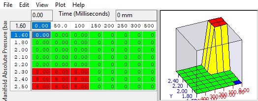
Gearchange - Wastegate Offset
A temporary change in the Wastegate duty triggered with an upshift to prevent boost spikes on gearshift caused by a sudden change in the air consumption of the engine as the RPM drops. The X axis is time since the start of an upshift, and the Y axis is the relative boost in Bar at the time the shift was triggered.
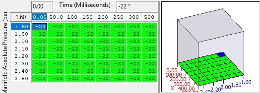
Gearchange - Ignition Minimum Allowed
A temporary lower limit on the final ignition timing value triggered by an upshift to prevent boost spikes on gearshift caused by a sudden change in the air consumption of the engine as the RPM drops. The X axis is time since the start of an upshift, and the Y axis is the relative boost in Bar at the time the shift was triggered.
Keep in mind that this will effect the amount of torque reduction achieved so may mean that gear shift quality is affected.
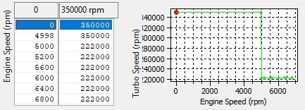
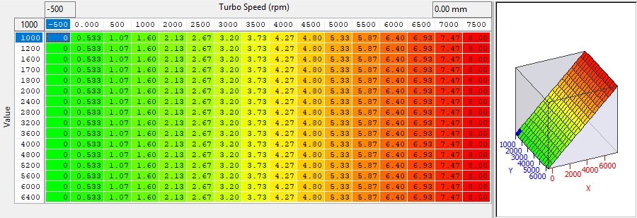
Wastegate Correction Turbo Speed Threshold
This map is the turbo speed limit, when the measured (or estimated for silver sport cars) turbo speed goes above this threshold the Wastegate Correction Turbo Speed Limit #1 - #3 maps are applied to maintain the turbo speed for turbo reliability. This map can be increased to allow the turbo to spin faster and increase the airflow/pressure.
Wastegate Correction Turbo Speed Limiter #1 - #3
When the Wastegate Correction Turbo Speed Threshold is exceeded, the offset in this table is applied to the absolute wastegate position reducing the achieved boost. This maintains a specific turbo speed preventing damage to the turbo due to over-speeding. The X-Axis is turbo speed above threshold, the y-axis is engine speed.
These maps 1 to 3 are the proportional integral and derivative WG offset maps used in the the closed loop turbo speed control on the high power models of VR30 engines. You shouldn't need to adjust these unless you are using the turbo speed limits as a target or your are seeing boost oscillating when its running on the turbo speed limits.
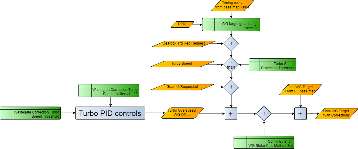
OEM Turbo speed Control and Gearshift Wastegate Correction
There are two types of VR30 engine a High and Low power version, the low power version (and the new hi power) cars don’t have turbo speed sensors. with this in mind there is overspeed protection measures to protect the turbo from harm when running above the safe turbo speeds defined by the factory. This is done using two methods,
one is general overspeed and uses a PID control loop to keep the turbo speed at the limit (using WG correction turbo speed maps above).
the other is a gear change WG offset.
The strategy is employed roughly as follows
it first does turbo speed checks
then if the turbo speed is too high it will use a PID control loop to reduce the turbo speed to the limit (based or turbo speed error)
then it will look at the Gear shift etc and add a WG offset if its triggered
OEM Gearshift Wastegate Correction
When the turbo speed is above the Gear shift offset turbo speed limit and a gearshift is occurring this value is added to the final WG position target. In Low Power variants the turbo speed is 0 so this function does not usually get applied. This map can be set to 0 and the RaceROM gearchange offset value used to prevent the over boost on shift due to the removal of BOV's from the VR30.
Alternatively if you set the turbo speed threshold for WG offset to a negative number the OEM function should trigger on the low power calibrations
(+44) 1895 811200 When dialing from within the UK, the country code is not required so dial 01895 811200 Open Hours Monday to Friday 9:00am - 5:00pm BST (UK Time) (4am-1230pm Eastern Standard TIme US) Visitors by appointment only EcuTek Tehnologies Ltd.Contact Us:
8 Union Buildings
Wallingford Road
Uxbridge, UB8 2FR
England
VAT No: GB 235 2616 23