/
GT-R RaceROM Launch Control, Rolling Launch and BOTL

GT-R RaceROM Launch Control, Rolling Launch and BOTL


GT-R ProECU Tuning Guide RaceROM Supplement: RaceROM Launch Control, Rolling Launch and BOTL


Table of Contents


This guide covers the RaceROM advanced Launch Control features.  For information on the RaceROM Launch Control refer to GT-R Factory Launch Control

RaceROM Launch Control, Boost off the Line (BOTL), and Rolling Launch

The RaceROM Launch Control feature allows you to adjust the launch control RPM live. This can be used to provide a higher or lower power/torque output during launch to suit the driver’s requirements.  In addition, you can specify a pre-launch manifold pressure target for each mapswitch mode. The ECU will dynamically retard and advance the ignition timing in order to achieve the target.  Launch control has been updated for Phase 6 with additional control of ignition retard for BOTL and a throttle compensation for retard to prevent engine speed from dropping significantly as retard is increased to achieve boost for launch.  Meanwhile Rolling Launch allows you to hold a steady vehicle speed while building boost to enable an abrupt acceleration forward.


Table of Contents


Method of Operation

The launch RPM is set in the Engine ECU and cannot be adjusted from the factory.

ECM ROM SeriesECM Launch Control RPM
JF Series (LC1)4500rpm
JW Series (LC3)3300rpm
KB KJ 38 Series (LC4)4100


EcuTek have developed RRLC so the Launch RPM can be adjusted LIVE during the Launch Mode. This allows the driver to select the optimum launch RPM (and therefore engine power output) for the current conditions.

RRLC allows the driver to adjust the launch RPM by pressing the cruise control “res/accel” and “coast/set” buttons while the launch control system is active.

With launch control active, whilst fully depressing the accelerator pedal, press the “res/accel” button to raise the launch RPM. Press the “coast/set” button to lower the launch RPM.  The default Launch Control RPM (set in the ECM ROM) will be used after ECU Programming, ECU Reset or disconnecting the battery.

If the RRLC is used to change the default LC RPM, then this new RRLC RPM is stored ready for the next launch (unless the ECU is programmed or ECU Reset etc).


Map List


Live Data Parameters

  • Dig: BOTL Active (True / False) – Flag showing if BOTL is active
  • Dig: Launch Control Active (True / False) – Flag showing if launch mode has been entered.
  • Launch BOTL Ignition Base (°) – BOTL Base ignition timing
  • Launch BOTL Igntion Proportional (°) BOTL proportional ignition correction
  • Launch RPM (RPM) – Current launch control target RPM including any overshoot
  • Launch RPM Base (RPM) – Current launch control RPM without any overshoot added.
  • Launch RPM Error – Difference between Actual and Launch RPM, positive is over target.
  • Launch Timer (s) – Time since launch mode became active

LC Flags

1 - BOTL Active 
2 - Throttle Integral Active 
4 - Launch Control active
8 - Post Launch
16 - Rolling Launch active
32 - Torque actual limit active

Note: These values are displayed as a sum e.g. 3 = 1 +2 = BOTL Active & Throttle Integral Active


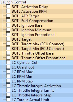
BOTL Activation Delay

Launch Control must have been active for at least this delay for BOTL to become active, this is usually not important as the timer will have expired by the time the activation RPM has been achieved.


BOTL Activation RPM

The Boost Off The Line Strategy will be enabled when the Launch RPM Error exceeds the upper value and remain active until is drops below the lower value. The lower value to disable BOTL is deliberately low to ensure that BOTL doesn’t cycle on/off due to RPM fluctuations caused by the BOTL itself.

Raising the upper value to -100 RPM will disable the BOTL retard from activating until later and may be useful for large turbo cars. Increasing the upper value to more than -50 RPM may have undesirable results as the actual RPM approaches the target launch RPM slowly once close to the target.


BOTL AFR Target

Fixed target AFR while in launch control (LC) mode.


BOTL Fuel Compensation

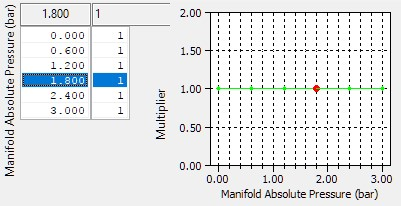
This can be used to multiply the fuel quantity while in launch control to make broad corrections for errors in AFR.


BOTL Ignition TIming Base

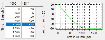
Sets the base timing while BOTL is active, instead of the main ignition map for each Mapswitch Mode. The ignition timing values are very low to promote making boost, but caution should be employed before lowering them too far as excessively retarded ignition timing will result in sluggish RPM control on launch and potentially boost that is too high and hard to control.


BOTL Ignition Minimum

This prevents an instantaneous significant ignition timing change due to BOTL from causing a sudden drop in engine RPM and subsequent cycling of RPM and BOTL switching on/off.

The input axis is time in milliseconds since BOTL became active, the output values are absolute ignition timing.


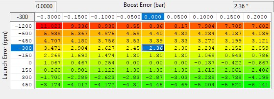
BOTL Ignition Proportional

For Phase 6 the Y axis is now Launch RPM Error and allows a change in retard to help stabilise the engine speed and prevent excessive retard while the RPM is still increasing to equal the target.


BOTL Target

A target of Manifold Absolute Pressure to achieve using the Boost Off The Line strategy, the default values of 0.5 represent 0.5bar absolute, in other words 0.5 bar of vacuum (at near sea level).


BOTL Target Max (ECU Connect)

Using EcuTek’s iPhone and Android companion App - ECU Connect, the BOTL target boost can be altered between limits set for each Mapswitch Mode. By default, both the min and max limit are set to the same default values for LC MAP Target and will require calibration to allow manipulation from within ECU Connect.


BOTL Target Min (ECU Connect)

Corresponding minimum limit for LC Map Target when adjusted from ECU Connect.


BOTL Throttle Offset Base

This adds an offset to the normal throttle angle depending on the current BOTL ignition retard, which is defined as the difference between the normal ignition timing as determined by the RaceROM Ignition Map for the current Mapswitch mode, and the current actual ignition timing as set by the BOTL strategy.

If the values in this map are made too high, the engine RPM will rise out of control, if left unchecked for more than about 1 second the OEM engine speed control strategy which will be trying to regulate the engine speed to match the current launch RPM, will start using fuel cuts to control the speed, and eventually close the throttle altogether.


BOTL Throttle Offset Proportional

This adds a further correction to the values in BOTL Throttle Offset Base used to correct for short term errors in launch RPM and BOTL manifold pressure target. The values in this table vary too much with changes in either input, RPM instability can result.


LC Cylinder Cut

If BOTL ignition retard is active, this map also allows for a variable amount of fuel cut using the same cut strategy employed in custom maps, the resulting fuel cut percentage will be reflected in the Cylinder Cut Probability live data value. This can be used to help regulate engine speed, lower boost or just make a lot of noise.

The default map is calibrated not to do any cutting when using the stock Launch control RPM.

Caution is advised using this map and restraint is recommended, you can damage an engine with prolonged use of BOTL and fuel cut.


Launch Control Overshoot

The overshoot RPM is added to the base RPM value to temporarily raise the RPM limit at the beginning of Launch Control to help the boost to be more quickly increased to the target level.

The input X axis is the time in milliseconds since the ECU entered launch control mode, the Y axis is the target Manifold Absolute Pressure requested by the BOTL strategy. For very high levels of MAP to be achieved it may be necessary to temporarily increase the launch RPM significantly. 

The live data value for Launch RPM will reflect the offset output by this map, while Launch Base RPM will only report the current base RPM as set using ECU Connect or the cruise control switchgear. Launch RPM Error will still be calculated using the current value for Launch RPM including any offset from this map.

When in launch mode and using the cruise control switch gear to adjust the base RPM, this overshoot will initially be applied, but once the overshoot RPM is 0 then the resulting LC RPM should be close to the base value. To adjust it’s recommended to enter launch control and wait for the RPM to stabilise before adjusting.


LC RPM Max

A maximum limit on the range of adjustment of the launch control RPM, as adjusted using either the cruise control switchgear or ECU Connect.


LC RPM Min

A minimum limit on the range of adjustment of the launch control RPM, as adjusted using either the cruise control switchgear or ECU Connect.


LC RPM Step

The launch control target RPM is adjusted by this value for each step when live adjusting the RPM using the cruise control switch gear.


Launch Control AFR Target 

This is the AFR Target applied prior to launch.


Launch Control Manifold Pressure Target 

This map allows you to specify a target manifold pressure in order to generate “Boost Off The Line”.


Launch Control Ignition Timing Base 

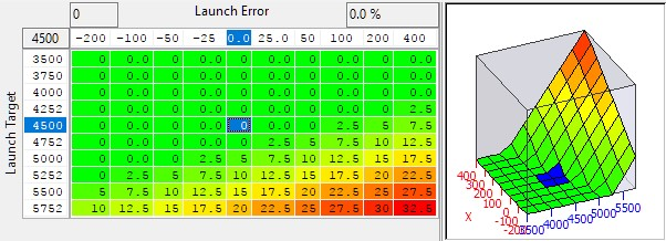
This map specifies ignition timing based on Manifold Pressure Target and RPM. Retarding the timing generates more manifold pressure. When calibrated correctly, the ECU should be able to maintain the target pressure prior to launch. 


Launch Control Ignition Timing Proportional

This map applies an adjustment to the base ignition timing based on the difference between the target and actual manifold pressure. If the pressure is below target, the map will retard the timing further, if the pressure overshoots the target, the map will advance the timing.


Launch Control VVT Adjustment 

This can be used to adjust the VVT angle to provide greater airflow across the engine during launch, therefore increasing boost pressure during launch.


RaceROM Rolling Launch

Rolling Launch throttle compensation has been updated with a different strategy for taking control of the throttle that should prevent spurious Drive-By-Wire related DTCs from being generated. The method of operation is otherwise unchanged and is detailed below (taken from existing manual).

As the name suggests, Rolling Launch is a type of launch control that can be performed from a rolling start.


To operate Rolling Launch, drive the car at a steady speed in a low gear - 60km/h in 2nd gear is about right. Set the cruise control to maintain the vehicle speed. Now press the accelerator pedal all the way down to the floor. Instead of accelerating, the ECU will initiate an anti-lag effect. This will rapidly generate a large amount of boost, controlled using a proportional closed loop mechanism. But the car will continue to hold steady at the selected vehicle speed. When you are ready to launch, press the CANCEL button on the steering wheel. The cruise control will disengage, the throttles will open fully and the ignition timing will advance. This unleashes a large amount of torque and causes rapid acceleration in an instance.

The rolling launch feature will work in any gear and at any RPM or vehicle speed.


Map List


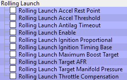
Rolling Launch Accel Rest Point

While Rolling Launch is enabled in cruise control mode RaceROM will set the Accel pedal input to see this voltage. The default voltage is essentially the normal at rest voltage, and means that cruise control will ignore the accel input and maintain the selected cruise control speed target while rolling launch is enabled.


Rolling Launch Accel Threshold

While the ECU will still see the Rolling Launch Accel Rest Point voltage, if the true accel voltage exceeds this threshold then the antilag function will be activated.


Rolling Launch Antilag Timeout

This specifies the maximum time limit for the antilag system to be active.  Once the antilag function has been triggered, it will be deactivated after this time to prevent overheating.


Rolling Launch Enable

Rolling Launch is enabled on a per Mapswitch mode basis and can be set to only be active when VDC is off and/or Race Suspension mode is enabled.


Rolling Launch Ignition Proportional

This is a proportional adjustment that gets added to the ignition timing according to the difference between the current manifold pressure and the target. The aim is to vary the ignition timing in order to keep the manifold pressure as close to the target as possible.  Used in conjunction with Rolling Launch Ignition Timing Base to deliver the Rolling Launch Target Manifold Pressure typically using increased retard to increase boost. The final ignition value will be capped at -30deg (30deg ATDC).


Rolling Launch Ignition Timing Base

While the Rolling Launch Antilag system is active, ignition retard is used to build boost. This specifies the base ignition timing according to the manifold pressure target overriding the values from the main ignition maps. This map should be calibrated such that the values used are close to the final value required to make the target boost at each RPM point. Typically, more retard will generate more boost, more advance will generate less boost.  Correction for boost target error comes from the Rolling Launch Ignition Proportional map.


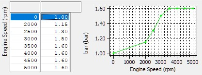
Rolling Launch Maximum Boost Target

A limit of Manifold Absolute Pressure to the boost target used by the Rolling Launch antilag system to prevent the driver from over working the turbo and engine at low RPM. The base target is set by the values in Rolling Launch Target Manifold Pressure but can be reduced at specific RPM using this map. The overall target will always be the lower of the two values.


Rolling Launch Target AFR

This specifies the target AFR when Rolling Launch retard is active. Separate targets may be specified for each of the four map switch modes.  this should be set reasonably rich to help keep exhaust temperatures from become extreme.


Rolling Launch Target Manifold Pressure

This specifies the base target Manifold Absolute Pressure while the Rolling Launch anti lag is active. Separate targets may be specified for each of the four map switch modes. The ECU chooses base ignition timing via the “Rolling Launch Ignition Timing Base”, then fine-tunes using the “Rolling Launch Ignition Timing Proportional” to try and achieve this target.

 This target is capped by the limits set in Rolling launch Maximum Boost Target and the result is used as the target for the ignition retard maps as part of the antilag system.


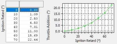
Rolling Launch Throttle Compensation

This map adjusts the throttles to compensate for torque variations as the ECU varies the ignition timing to generate boost. The compensation is now an absolute throttle angle adder and the above table has shown to give sensible results but may need fine tuning.  If the car decelerates during antilag then increase the values slightly. If the car accelerates during antilag then decrease the values slightly. Otherwise do not adjust.


EcuTek ProECU tuning tools tools should only be used by experienced tuners who understand the product and engine calibration. 
If you do not fully understand this product then you WILL damage your engine, ECU or your vehicle. 
Please ensure you fully read all EcuTek manuals BEFORE attempting to use ProECU with your laptop or your vehicle. 
Use with extreme caution and understanding at all times, if in doubt then do not proceed. 
EcuTek accepts no responsibility for any damage to the engine, ECU or any part of the vehicle that results directly or indirectly from using the product.


** If you are in any doubt that you do NOT have the experienced required to use this product then you should NOT USE IT **


Retail customers

** If you have any doubt that you do NOT have the experienced required to use this product then you should NOT USE IT, you should simply contact your EcuTek Master Tuner shown clearly on the top of your Programming Kit or visit your preferred tuning shop to have a professional tuner to use it for you ** 

Contact Us:

EcuTek Technical Support

support@ecutek.com

(+44) 1895 811200

When dialing from within the UK, the country code is not required so dial 01895 811200


Open Hours

Monday to Friday 9:00am - 5:00pm BST (UK Time)

(4am-1230pm Eastern Standard TIme US)

Visitors by appointment only


EcuTek Tehnologies Ltd.
8 Union Buildings
Wallingford Road
Uxbridge, UB8 2FR
England

VAT No: 
GB 235 2616 23


Related pages