GT-R RaceROM Boost Control
- Brandyn Mowat
Ecutek Boost Control vs RaceROM Boost Controller
There may be some confusion between the features for boost control in recent RaceROM versions, despite the similar naming due to historic reasons the two RaceROM features have different functions.
Ecutek Boost Control
Ecutek Boost Control is the control strategy to set the boost target and control the wastegate solenoid such that the boost reaches and remains on target.
RaceROM Boost Controller
(abbreviated to RBC) is a feature used to limit the boost target using the cruise control switchgear. The maximum boost target is displayed on the boost gauge of the MFD. As can be determined from the boost target flow diagram the boost target can be below the value set by the RBC but it can never exceed it.
Absolute Boost
The single most important concept introduced with Phase 5 GTR is the use of Manifold Absolute Pressure (MAP) for all aspects of tuning the boost control. All boost target, boost limit and boost threshold values are all absolute values in Bar. Tuners will now find that all boost related maps and live data will give consistent readings regardless of altitude, and calculations will hold true in all circumstances.
RaceROM Boost Controller values still correspond to the stock to the gauge, so 1.5bar still equates to 1.5bar of relative boost at sea-level.
To make tuning as simple as we can we have added an atmospheric compensation that by default gives a consistent “boost” at all altitudes, but the result is that your MAP will drop as a result, and power will be reduced at altitude if using the default Boost Target Atmospheric Compensation map.
To ensure that boost tuning is as simple and intuitive as possible, we have corrected the Nissan boost gauge display to show true manifold gauge pressure that will always correlate with the current atmospheric and absolute manifold pressure. Without this correction, your Nissan GTR boost display has been lying to you, displaying instead manifold absolute pressure – 1 resulting in strange behaviour at altitude. It has also been inconsistent with the actual boost level as measured by an independent gauge, such as the boost input on a dyno. This correction can optionally be disabled.
Boost Target Calculation
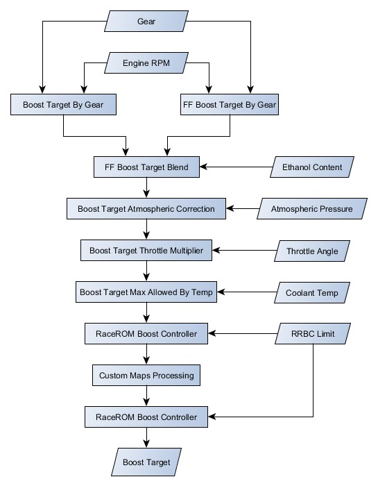
The boost target is obtained following the below flowchart. You will see that the RRBC limit is imposed both before and after custom maps processing, this ensures that custom maps cannot raise the limit beyond the limit set from the RRBC.
The RRBC is a final limit to any boost target, any boost target higher than the RRBC limit will be capped to the RRBC limit.
Enable Special Features (Boost Control Related)
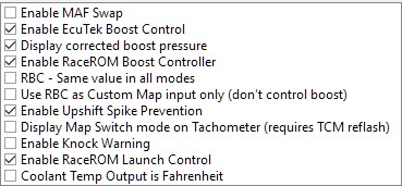
Enable EcuTek Boost Control
Overall enable for the RaceROM boost control strategy used instead of the OEM turbine flow based strategy. Enabled by default and highly recommended.
Display corrected boost pressure
By default, the boost gauge shows (absolute pressure – standard atmospheric pressure) which means at altitude with the engine not running it will report a negative number. This options corrects the boost gauge to show a true relative pressure of (manifold absolute pressure – atmospheric pressure)
Enable RaceROM Boost Controller
Overall enable for the RBC, enabled by default. If turned off the cruise switchgear will do nothing RBC related.
RBC – Same value in all modes
Forces the RBC setpoint to be maintained even when switching MapSiwtch Mode. There is a limitation of this that ALL modes will have a maximum setpoint corresponding to the lowest of the four values in Boost Controller Maximum.
Use RBC as Custom Map input only
The RBC can be an excellent tool for interacting with Custom Maps. This option allows a value to be set using the cruise control switches, displayed on the boost gauge, but the value is not used as a limit to boost target. It is however available to use as a custom map, and used for example to adjust traction control implemented using Custom Maps.
Enable Upshift Spike Prevention
Overall enable for the USP strategy.
Map List
Live Data
- Boost Bank1/Boost Bank2 – Absolute pressure in bar, measured by the two boost sensors
- RBC Maximum Desired Boost – Relative boost max target, matches number format on gauge
- Boost Target – Absolute pressure target in bar, measured by the intake manifold pressure sensor
- Boost Error – Difference between MAP and Boost Target, positive numbers are over boost
- Manifold Gauge Pressure – “Boost” pressure measure in bar above the current atmospheric pressure
- Manifold Absolute Pressure – Absolute pressure in bar, measured by the intake manifold pressure sensor
- Wastegate Duty – The duty cycle applied to the wastegate solenoid (Same as Final Duty)
- WG Duty Base – Output from Wastegate Duty Base maps
- WG Duty Adder – Correction resulting from Gear/IAT multiplier step
- WG Duty Integral – WG duty added by Integral correction of EcuTek boost control strategy
- WG Duty Proportional – WG duty added by Proportional correction of EcuTek boost control strategy
Boost Limit Fuel Cut
The manifold absolute pressure needs to exceed this limit, measured in Bar (relative) by the manifold pressure sensor, for a time that exceeds Boost Limit Fuel Cut Delay, to trigger a fuel cut as an overboost safety measure.
Boost Limit Fuel Cut Delay
Time period in seconds the ECU will wait before triggering a fuel cut when the manifold relative pressure exceeds the boost limit as set by the Boost Limit Fuel Cut.
![]()
Boost Limit Fuel Cut Hysteresis
Previous versions of RaceROM used separate cut and resume maps to introduce hysteresis into the fuel cut. However, in version 6 we have introduced a single value to set the hysteresis to simplify setting the boost limit fuel cut and conserve space within the ROM. With the default limit of 2.4Bar and hysteresis of 0.6Bar, the fuel will be cut when the MAP exceeds 2.4Bar for 0.2 seconds and resume when the MAP drops below 1.8Bar.
![]()
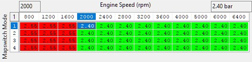
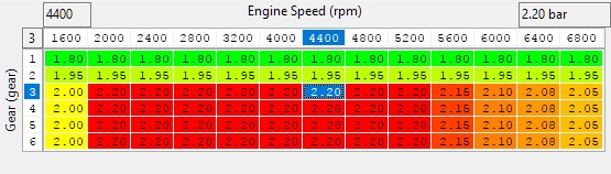
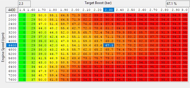
Boost Target by Gear
Boost target is no longer defined using a 3D map with RPM and throttle axis’, instead the target is defined by gear and RPM, with throttle modulation coming in the form of a simple 2D map. There is also a corresponding boost target for FlexFuel operation named FF Boost Target By Gear and can be found in the RaceROM FlexFuel category.
An RPM dependant target boost profile is set on a per gear basis. Typically gears 1 and 2 have noticeably lower targets due to traction limitations.
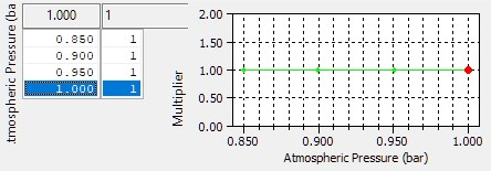
Boost Target Atmospheric Compensation
The boost target can be offset for changes in atmospheric pressure the default map values reduce the absolute boost target 0.1Bar for each 0.1Bar drop in atmospheric pressure. This is suitable for stock turbos which will often be pushed to their maximum at sea level, and pushing the same absolute pressure at altitude can be detrimental to the turbos while not giving the desired pressure.
If working with turbos that have plenty of headroom at sea level then flattening this map to 0 will give the same absolute pressure target at altitude, and result in similar power levels.
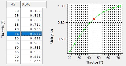
Boost Target Throttle Multiplier
The boost target as adjusted by the Boost Target Atmospheric Correction map is multiplied by the output of this map. For example a target of 2.4bar x 0.45 = 1.08 bar absolute.
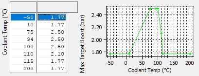
Boost Target Max Allowed By Temperature
Maximum target based on engine coolant temperature, used as a maximum limit for boost target at normal engine temps and reduced significantly at excessive temps for engine safety.
Wastegate Duty Calculation
The Wastegate duty calculation follows the process below, the closed loop control consists of a base wastegate duty that blended from a high and low altitude base map def into a base multiplier for IAT/Gear. The base duty is always subject to a proportional correction, and an integral correction term is calculated and added only when MAP, Boost Error and Throttle Angle tests are met. There is an overall enable of boost control based on RPM, and the wastegate duty is always zero if the engine speed is below this RPM threshold.
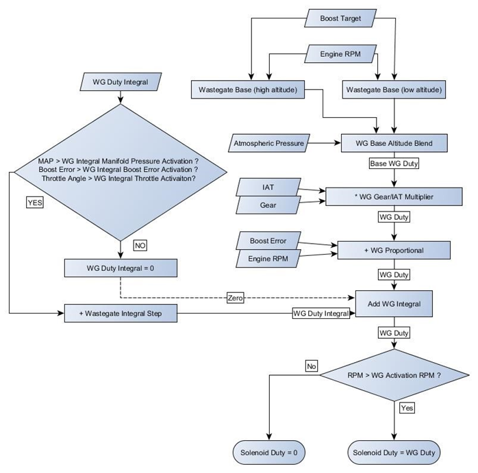
WG Activation RPM
The wastegate solenoid will not be active until this RPM is reached.

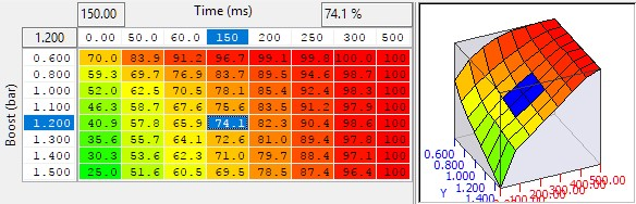
WG Base Duty(Low Altitude)
WG Base Duty (High Altitude)
These two maps are used to set a base duty for high and low altitudes, which are combined using the Wastegate Base Altitude Blend map. The X-Axis is target boost in bar (Absolute) and the Y-Axis is engine speed.
WG Base Altitude Blend
This map defines how the high and low altitude base maps are combined to produce the wastegate base duty. A value of 1.0 uses only the value from the low altitude (sealevel) base map, a value of 0.0 uses only the value from the high altitude base map. The final value for WG Duty Base is calculated as:
𝑊𝐺 𝐷𝑢𝑡𝑦 𝐵𝑎𝑠𝑒 = (𝑊𝐺 𝐵𝑎𝑠𝑒 𝐷𝑢𝑡𝑦 (𝑙𝑜𝑤 𝑎𝑙𝑡𝑖𝑡𝑖𝑑𝑒) × 𝑊𝐺 𝐵𝑎𝑠𝑒 𝐴𝑙𝑡𝑖𝑡𝑢𝑑𝑒 𝐵𝑙𝑒𝑛𝑑)
+ (𝑊𝐺 𝐵𝑎𝑠𝑒 𝐷𝑢𝑡𝑦 (ℎ𝑖𝑔ℎ 𝑎𝑙𝑡𝑖𝑡𝑖𝑑𝑒) × (1 − 𝑊𝐺 𝐵𝑎𝑠𝑒 𝐴𝑙𝑡𝑖𝑡𝑢𝑑𝑒 𝐵𝑙𝑒𝑛𝑑))
The example shown below uses the high altitude base map at 0.85 bar atmospheric pressure and the low altitude base map at 1.00 bar atmospheric pressure with linear interpolation in between.
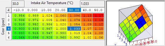
WG Gear/IAT Multiplier
The output of the Wastegate base duty map can be multiplied to increase or decrease it to compensate for changes in intake air temp and/or gear. Typically the base duty is increased with values greater than 1.0 for lower gears (1st/2nd) to improve spoolup with rapidly changing RPM. Conversely the base duty is often decreased with values of less than 1.0 for higher gears (5th/6th) to prevent overboost with increasing load and slower RPM rates.
WG Integral Boost Error Activation
A threshold of boost error with hysteresis to enable integral closed loop control of the wastegate duty. Integral feedback is activated when the upper value is exceeded and remains active until the error drops below the lower value. This table can be used to stop integral windup when at full throttle and waiting for the boost to rise.
Integral correction will only begin when the conditions for Boost Error, MAP and Throttle are met, and will be reset to zero if any one of these conditions are not met

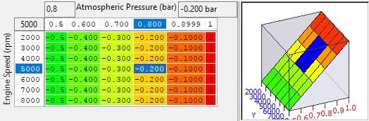
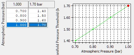
WG Integral Manifold Pressure Activation
A threshold of manifold absolute pressure above which the integral correction is activated.
This table can be used to stop “integral windup” by preventing integral feedback under conditions where the boost control cannot realistically achieve any target boost. The input axis is Atmospheric pressure, and allows the tuner to lower the threshold in line with the drop in atmospheric pressure. Typically this table is set at or slightly below the base pressure for the actuator or wastegate.
WG Integral Manifold Pressure Hysteresis
Manifold Absolute Pressure must fall below WG Integral Manifold Absolute Pressure Activation by this value for the integral correction to become inactive.

WG Duty Integral Step
Wastegate Integral correction builds up over time. While active (see above conditions) this map dictates how much the integral value is increased with each cycle of the boost control loop. Each loop takes just 10ms (one 1/100 of a second) and the current integral correction can be observed by checking the WG Duty Integral live data parameter which is logged by default.
WG Duty Integral Min/Max
The integral correction can be limited with these two values. The minimum limit is the top value and the max limit is the lower value. On cars running significantly larger turbos than stock, these values can be scaled down in line with the expected lower wastegate duty. Values of approximately +/- 20% of your max final duty will be a good start.

WG Integral Throttle Activation
A threshold of throttle angle with hysteresis to enable integral closed loop control of the wastegate duty. Proportional and integral feedback is activated when the upper value is exceeded and remains active until the throttle angle drops below the lower value. This table can be used to stop overactive closed loop corrections under light load conditions.

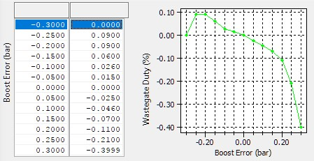
WG Proportional
Proportional correction is absolute wastegate duty added or subtracted at an instant in time based on the current boost error. The default maps have high positive values when the boost is under target at low RPM while in spool up. Using high proportional values is preferable to high integral values to prevent windup but still results in high wastegate duty on spool.
WG Upshift Compensation
A temporary change in the Wastegate duty triggered with an upshift to prevent the boost spikes on gearshift caused by a sudden change in the air consumption of the engine as the RPM drops. The X axis is time since the start of an upshift, and the Y axis is the relative boost in Bar at the time the shift was triggered.
EcuTek ProECU tuning tools tools should only be used by experienced tuners who understand the product and engine calibration.
If you do not fully understand this product then you WILL damage your engine, ECU or your vehicle.
Please ensure you fully read all EcuTek manuals BEFORE attempting to use ProECU with your laptop or your vehicle.
Use with extreme caution and understanding at all times, if in doubt then do not proceed.
EcuTek accepts no responsibility for any damage to the engine, ECU or any part of the vehicle that results directly or indirectly from using the product.
** If you are in any doubt that you do NOT have the experienced required to use this product then you should NOT USE IT **
Retail customers
** If you have any doubt that you do NOT have the experienced required to use this product then you should NOT USE IT, you should simply contact your EcuTek Master Tuner shown clearly on the top of your Programming Kit or visit your preferred tuning shop to have a professional tuner to use it for you **