GT-R RaceROM Injector Calibration
Brandyn Mowat
Paul Blamire
Even good injectors are not perfect, and can suffer from inaccurate fuelling at light and low low pulse widths. With EcuTek RaceROM Phase 7and beyond, Injector scaling you can speed up the tuning process and get better results for your customer by following the basic steps below.
- Find injector data and fit injectors
- Set the injector flow rate
- Set the injector lag time values
- Set appropriate minimum open times
- Set the low pulse width compensation function up
- Add fuel pressure and temperature compensations if sensors are available
If you were loking for information on OEM injector scaling head over to Scaling Injectors For Nissan Using OEM Method (GT-R, 370z)
In this article, we will look at the Version 7 and above RaceROM method for characterising injectors for the Nissan GTR Port injection engines i.e. VR38. The RaceROM strategy differs from the Nissan strategy significantly but matches the typical aftermarket injector definitions normally found and gives exception results when tuned correctly. We will go through the following maps
- Primary Injector Flow Scaling (RaceROM)
- Primary Injector Lag Time (RaceROM)
- Injector Low Pulse Width Compensation
- Injector Minimum Open Time
- Fuel Pressure Compensation
- Fuel Temp Compensation
These variables can be found in the Fuelling category under the Injectors section of the ROM file.
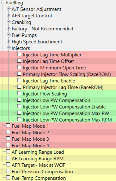
There are many resources for injector information that may help out including the link here, Engine Labs Injector Article.
The basics of RaceROM Injector scaling.
Injector flow scaling is a combination of simple concepts which when properly set up can make very repeatable fueling. There are generally 3 options that aftermarket injectors classify
- Injector Flow Rate - the amount of flow the injector can achieve at set pressure using the test rig that the injector manufacturer or tester has set up.
- Injector Lag Time - Also known as Latency or dead time is the time from when current is applied to the injector coil until fuel starts to flow. This may also differ from calibration data sets as the fluid type and drive characteristics of the test machine will be slightly different than that of the GTR ECU and fuel system.
- Low Pulse Width Correction - This is the value that is intended to compensate for the non linear flow rate found at low injector open times.
The injector data is very important for use as a reference when setting up your injectors, injector manufacturers like Injector Dynamics, ASNU and Fuel Injector Clinic all give data in this format and some of them can be copied directly into the maps as a starting point. See the example Below of sample data from ASNU.
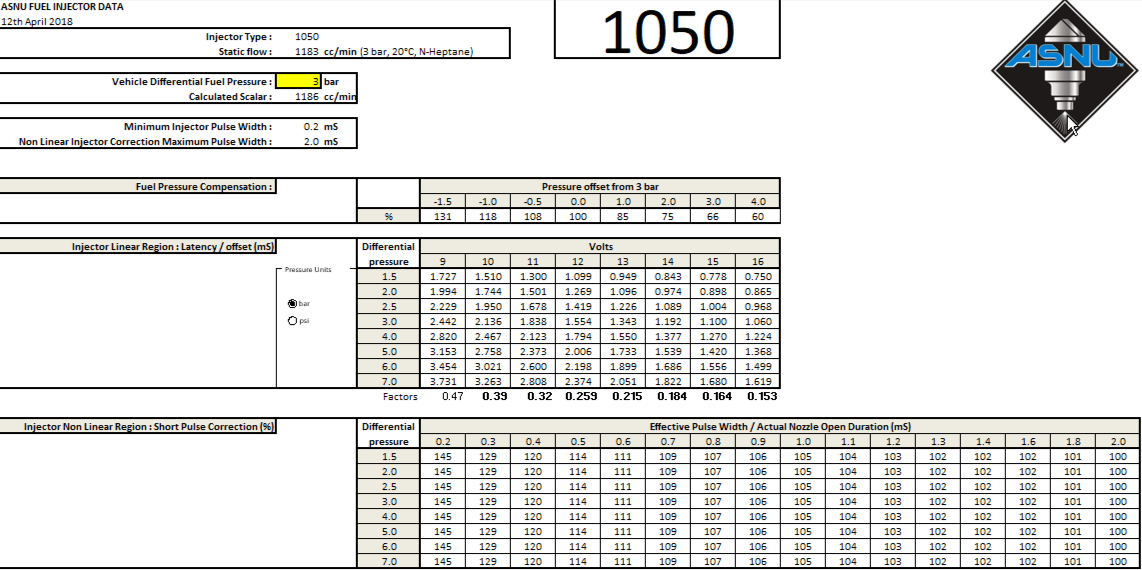
The values that manufacturers give may not be exactly the same as what you find give the correct fueling. There are generally many differences between the test rigs the manufacturers use and the Nissan GTR fuel rail (test pressure, rail type, length, harmonics, fluid type, currents etc) so you may see minor differences to advertised settings.
Primary Injector Flow Scaling (RaceROM)
The injector scaling data used should be close to advertised size, however we do tend to see that aftermarket injectors generally do not exactly match the suppliers flow rate data, this is dependent on the manufacturers test methods.
Keep in mind that the ECU does not know the actual injector size but instead uses a multiplier value scaled to match the stock injector size. We find that our own EcuTek 1050cc injectors are best represented by a flow scaling of 1050-1100cc.
There is an OEM value in all ROMs which we DO NOT recommend using as it is limited to 800cc. Instead we recommend you use the Injector Flow Scaling (RaceROM) map. With this map you can select Injector scaling values for each of the 4 Map Switch modes. This is useful if alternate fuels are used, for example if using E85 you can simply reduce the Injector scaling size by 30% and the ECU will deliver +30% more injection volume. The top value is for mapswitch MODE 1 the bottom value is MODE 4.

EcuTek can supply high-quality Bosch Motorsport injectors that have a rated flow of 1050cc, (enough for 1000+bhp on a GT-R) they are tried and tested and they do not suffer from some of the idle and black smoke issues that some other well known brands do. See the webstore and Nissan GT-R R35 Motorsport 1050cc Injector Kit Manual for more information.
You can find the injector flow rate at your base fuel pressure in the data sheets supplied and enter it into the Injector Flow Scaling (RaceROM) map. The injector size can be manipulated if required to get the high load fuel trims as close to 100% as possible (+-5% is achievable).
Primary Injector Lag Time (RaceROM)
Nissan do not use a standard injector curve because the IPDM (Intelligent Power Distribution Module) constantly maintains injector voltage very close to 14V (unlike other manufactures), for low voltage cranking they use the cranking injection table to compensate for battery voltage drops.
When using larger pumps, alternators or other ancillary equipment it may have significantly different characteristics to the stock equipment and may cause voltage and pressure differences. To improve tuning of larger injectors or account for upgraded equipment on the GTR we have introduced a new 3D map for injector lag time based on battery voltage and fuel pressure (the two biggest influences on lag time).
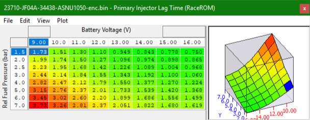
Make sure to enable the 3D lag time map in the software otherwise the OEM Nissan value will be use instead.

You should start with the available manufacturer data as a base and tune the appropriate regions if required. Injector lag time errors have the greatest effect at low pulse widths as the percentage of open time of the error is higher, this table could be tuned at lower pulse widths above that seen in the Low Pulse width compensation maps.
Injector Low (PW) Pulse Width Compensation
All Injectors exhibit a deviation from the linear flow rate when the total injector open time is close to the lag time values (i.e. low effective pulse-widths). To allow adequate fuel delivery at higher loads larger injectors are required however they are still required to maintain the correct fuel amount at idle. Injectors don't flow linearly at low effective opening times like at idle which affects the fuel delivered. Low Pulse Width correction can be used to account for the non linear fuel flow rates in these regions and perfect the amount of fuel delivery.
In some cases the maximum and minimum required fuel delivery range can be so large that staged injection will be required to allow adequate control at low and high demands.
RaceROM allows you to adjust the final actual pulse width based on the effective pulse-width (Pulsewidth before any lag time added) to compensate for the altered fuel delivery. The Injector Low PW Compensation map multiplies the effective pulse with by the correction factor to get the final pulse-width. Use the data from the Injector supplier to get a base line correction and adjust the values increasing them to get more fuel and decreasing them to get less.

Version 6 patches are slightly different in output the effect injector size not pulsewidth so effectively invert the correction. The change of method in phase 7 brought the method in line with industry data.
To use the maps make sure they are enabled in the correct map switch mode.

There are engine speed and injector open time limits to stop the LPW correction maps working engine speeds and you can use the injector manufacturers data to selecting these deactivation points.


Fuel Pressure Compensation
With RaceROM version 7 changes in fuel pressure can be compensated for using the Fuel Pressure compensation map, a Fuel pressure sensor should be configured using the new sensor options. To set up the sensor see the RaceROM version 6 manual or the Fuel pressure sensor set up article.
Relative Fuel Pressure is used in the Fuel Pressure Compensation maps and represents the pressure difference between the inlet (fuel rail) and nozzle (inlet port) pressures, it is calculated as:

To calculate the fuel Pressure compensation the following formula can be used. It uses the Set base fuel pressure relative to manifold pressure (Nominal relative Fuel pressure) and the actual measured relative fuel pressure to set a correction value
. 
A table can be populated using the values for different base pressure much like below.
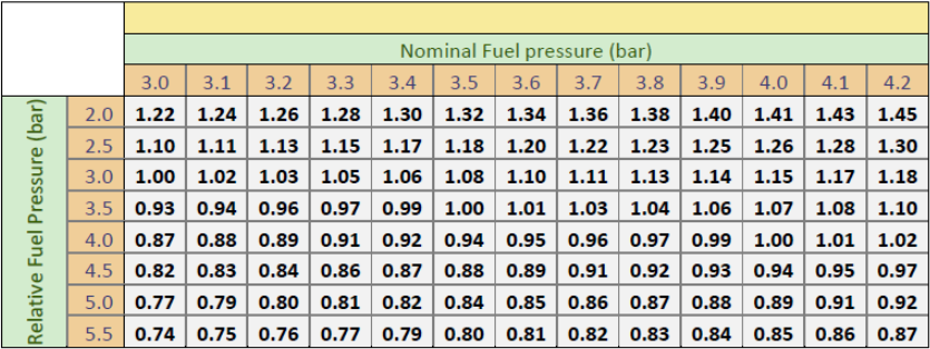
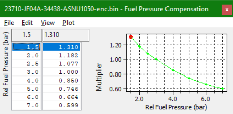
You could use the column from this table for the set relative base pressure (3.5 bar on a standard GTR) in the Fuel Pressure Compensation map as a base value. The ASNU example data has these value already determined and can be seen below.
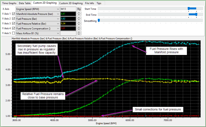
To demonstrate the fuel pressure compensation working you can see that the relative fuel pressure increases with manifold pressure to show the the regulator is performing correctly. However the fuel flow rate with only the primary fuel pump running is not enough to maintain the relative fuel pressure until the secondary pump starts, the fuel pressure compensation take car of this by increasing the injection amount to keep the AFR constant.
Fuel Temperature
When tuning a car with a fuel temperature sensor, it is possible to compensate for changes in the fuel temperature. Typically fuel pulse width is increased with increasing fuel temperature to compensate for the drop in fuel density, values greater than 1.0 will increase the amount of fuel delivered.
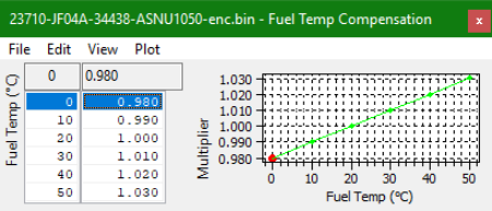
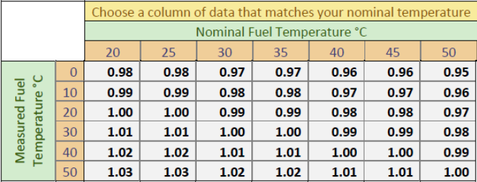
The table below outlines the approximate multiplier required to correct for a difference in fuel temperature.
Contact Us:
(+44) 1895 811200
When dialing from within the UK, the country code is not required so dial 01895 811200
Open Hours
Monday to Friday 9:00am - 5:00pm BST (UK Time)
(4am-1230pm Eastern Standard TIme US)
Visitors by appointment only
EcuTek Tehnologies Ltd.
8 Union Buildings
Wallingford Road
Uxbridge, UB8 2FR
England
VAT No: GB 235 2616 23
