GT-R TCM Tuning Guide
- Brandyn Mowat

GT-R ProECU Tuning Guide: TCM Supplement
Live data
A full list of live data parameters can be found in the service manual, however the most important ones are listed below.
- Accel Position sensor 1 (%) - Actual Accel pedal driver input
- Accel Position sensor 2 (%) - Effective Accel position including adjustment by (for example) cruise control
- Clutch A Pressure (Bar) - Measured pressure on Clutch A Clutch A Slip (RPM) Engine RPM – Clutch A output RPM
- Clutch A Speed (RPM) - Clutch A shaft RPM
- Clutch A Pressure Target (bar) - Target pressure on clutch A the TCM control will try to maintain Clutch A Temperature (°C) Estimated temperature of clutch A based on friction, load and slip
- Clutch B Pressure (Bar) - Measured pressure on Clutch B Clutch B Slip (RPM) Engine RPM – Clutch B output RPM
- Clutch B Speed (RPM) - Clutch B shaft RPM
- Clutch B Pressure Target(bar) - Target pressure on clutch B the TCM control will try to maintain Clutch B Temperature (°C) Estimated temperature of clutch B based on friction, load and slip Engine Speed 1 (RPM) - Engine RPM
- Engine Torque Available (Nm) - Estimated engine torque potential without any reductions active
- Engine Torque Demanded (Nm) - Engine torque requested by driver, sent from ECM
- Engine Torque Limit Request (Nm) - Torque request sent to ECM to cut power on upshift
- Engine Torque Limit Request2 (Nm) - Torque request sent to ECM to limit push after downshift blip (when req)
- Fluid Temperature (°C) - Bulk temperature of transmission fluid G Force Lateral (G) Lateral (left/right) G-Force from the G sensor
- G Force Longitudinal (G) - Fwd/Rev G-Force as calculated from rate of change of vehicle speed
- Gear Current - The Gear the TCM is actually in (may be different to display) Gear Desired The Gear that the TCM is trying to shift to
- Gear Planned - The next gear that will be shifted into if requested (preselected next gear) Gear Indicator Gear as shown on the dash indicator
- Line Pressure (Bar) - Main hydraulic system pressure
- Mode (0 to 5) - 0=Auto, 2=Auto (Race), 3=Manual, 4=Manual(Race), 5=Snow/Eco
- XXXX S/V Commanded (%) - Solenoid valve current commanded by TCM for various solenoids
- XXXX S/V Monitored (%) - Solenoid valve current measured by TCM for various solenoids
Early Gen 1 TCM ROMs will log at approximately 10 Hz while the later ROMs such as the KJ series (both 1mb) log at 50hz. TCM logging speed is unaffected by the number of logging parameters enabled as all the data is returned no matter what the request.
EcuTek recommends the programming of all 2008-2010 TCMs with the latest KJ series ROMs as they offer a number of improvements, of which logging speed is just one, more detailed explanation of ROM choice is covered later in this manual.
The Upshift Sequence
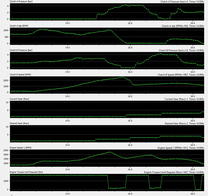
The upshift sequence can be broken down into three phases:
- Take up – The incoming clutch (the clutch that will be engaged in the next gear) is preloaded with light pressure and starts to slip, taking up any slack in the transmission.
- Outgoing clutch transfer – The pressure on the outgoing clutch (the clutch that was engaged before the shift was initiated) is ramped down and finally reduced to zero.
- Incoming clutch transfer – The incoming clutch pressure is ramped up, finally to the current target clutch pressure. This can happen simultaneously with outgoing clutch transfer, or in the case of shifts at high torque it happens after to avoid significant pressure being applied to both clutches at the same time.
During the either or both of the clutch transfer phases the torque is reduced by the TCM via a torque request sent to the ECM via CANbus.
The screenshot shows the stages on a gentle upshift from 1st to 2nd gear.
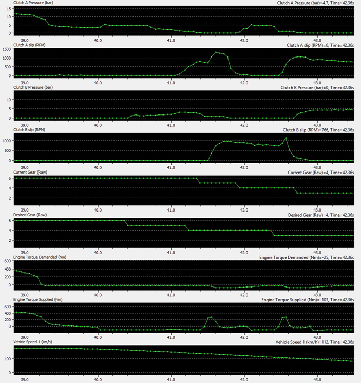
Downshift Sequence
The downshift sequence is very similar to the upshift sequence, due to the low torque outputs present in overrun conditions (typically negative due to the transmission driving the engine) clutch pressures are considerably reduced and it can be difficult to see exactly what is going on. In the below example the log shows downshifting on gentle deceleration from 6th through to 3rd gear, it’s worth noting that unlike upshift under even light load the clutch pressures are low and often there is no definitively engaged gear.
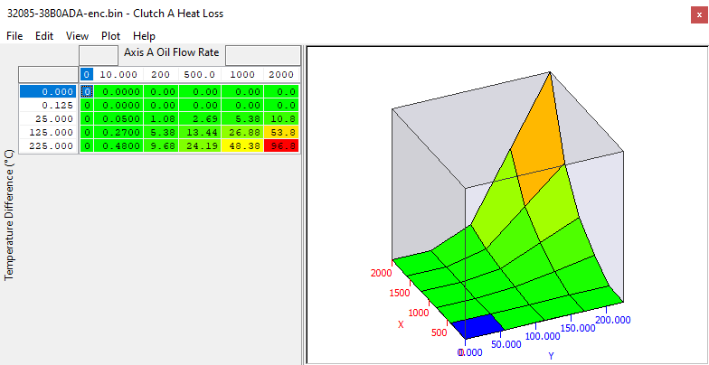
Clutch A/B Heat Loss
Clutch temperature is estimated by the TCM based on friction, RPM and clutch pressure for heat input and oil flow for cooling. The heat loss maps dictate the heat rejection from the clutch (into the oil) based on the temperature of the oil and the flowrate through the clutches. These maps are usually left standard.
Clutch Temperature Threshold 1-4
In maximum effort drag cars it may be required to raise these thresholds so they are more representative of the capabilities of an uprated clutch, or in situations where the TCM overestimates the heat input encountered with an uprated clutch. Raise all 4 thresholds together to avoid clutch temperature protection thresholds to be hit, thereby preventing limp mode situations after a number of launches, and prevent loss of clutch pressure during a drag run.
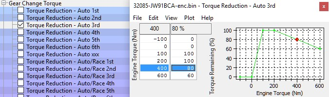
Gear Change Torque
During an upshift under load the TCM sends a request for a reduced torque level to the ECM, the ECM responds with a reduction in ignition advance to try and meet this new reduced torque level. The “Gear Change Torque” maps set what percentage of the Engine Torque Available should remain, the output of this map is still subject to small corrections so you may not see torque figures that exactly match the output of these maps.
The following 3 examples show the output torque requested in a few different scenarios using the stock maps.
Example 1:
Input torque = 500Nm
Map output = 70%
Requested torque = 350Nm
Example 2:
Input torque = 700Nm
Map output = 60%
Requested torque = 390Nm
Example 3:
Input torque = 1100Nm
Map output = 60%
Requested torque = 660Nm !!!
In the case of 1100Nm input (not unknown on high power drag car) the output 660Nm, this still very high torque value can cause issues with shifting as the increased clutch slip and time to speed match results in longer overall shift times and potentially damaged clutches. Therefore on very high powered cars it’s possible to rescale the input to (for example) 1000Nm and reduce map value to more like 35% giving 385Nm Shifting torque even at 1100Nm.
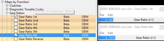
Gear Ratios
Gear ratio data is set individually for each gear including reverse, used for calculation purposes and is very important to be correct. Adjusting the ratio for a long 6th gear is a common procedure, however do not adjust these to compensate for changes in final drive ratio as the TCM compares output shaft A/B RPM with the engine RPM. Shifting can stop happening at all and/or become very poor when inappropriate values are used.
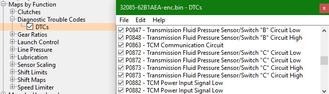
Diagnostic Trouble Codes
In a small number of cases it may be required to disable a DTC within the TCM. However most DTCs reported by the TCM are critical to operation and normally mean a fault is present. P2637 and P2641 are common DTCs and normally solved by making changes at the ECM, typically MAF voltage limits or bad torque estimation is the cause.
WARNING: do not assume that a DTC error code only requires something to be switched off in the TCM rom! Many functions on the ECU side may also utilize information from the transmission and vice versa.
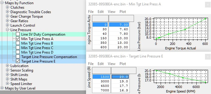
Line Pressure
“Line Pressure” is the system pressure for the transmission’s fluid reserve, which is then used and regulated to a lower pressure for specific sub systems within the transmission such as clutch pressure and shift solenoids. Therefore clutch pressure can never be higher than line pressure, so keep in mind that high demands on clutch pressure will require changes to the minimum target line pressure.
The Target Line Pressure Compensation map can be used to increase the line pressure at high temperatures and higher RPM if there are problems in maintaining the clutch pressures.
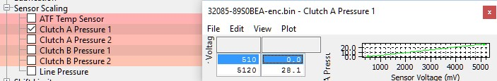
Sensor Scaling
- ATF Temp Sensor - The transmission oil temperature sensor can be rescaled for non-standard temperature sensors.
- Clutch A Pressure 1 and Clutch B Pressure 1 - Sensor scaling for clutch and line pressures (line pressure not available on all ROMs). Two pairs of values give an overall slope for the sensor, these are the normal values used when the TCM zeros the sensor scaling. The final scaling is usually in line with the values here.
- Clutch A Pressure 2 and Clutch B Pressure 2 - Sensor scaling for clutch and line pressures (line pressure not available on all ROMs). Two pairs of values give an overall slope for the sensor, these are the LOWER limits used when the TCM zeros the sensor scaling and are typically 290mv lower than the Pressure 1 values.
Shift Maps (Adaptive Shift Control)
Introduction to ASC
When driven in Auto the TCM monitors how aggressively the car is being driven and selects one of 4 shift schedules depending on how demanding the driver is, Nissan calls this "Adaptive Shift Control" or ASC. Using inputs including G forces, steering input, road speed, engine RPM, torque demand, pedal inputs and transmission mode, the TCM calculates a "demand" which goes up when driving hard and decays down when driving in a more relaxed manner. As the demand goes up so does the shift map that the TCM chooses, although Nissan simplify this to a more basic concept in the following table.
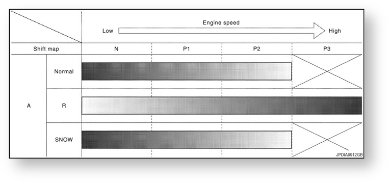
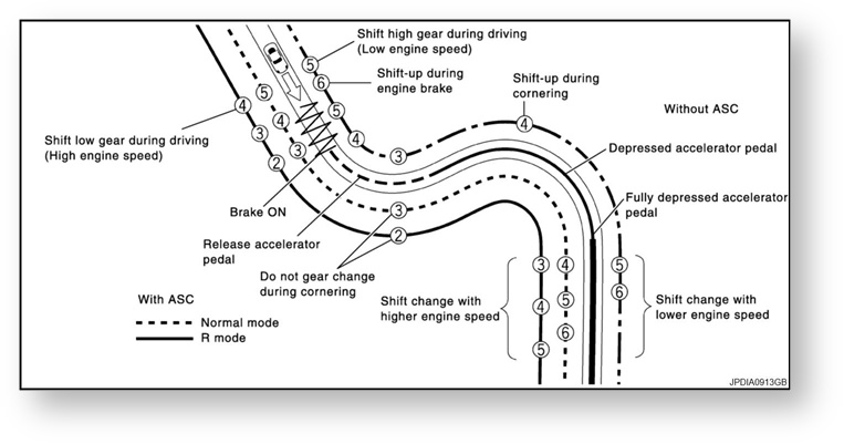
The difference between driving the car in Normal and R mode are described by Nissan in terms of resulting gear in following diagram.
ASC Group N - P3
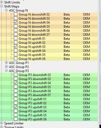
For normal driving in Auto mode the ASC shift maps are the ideal starting point to change the driving experience of the car, especially to prevent the TCM shifting into high gears at low speeds, a particular problem on modified cars. In ProECU there are maps for each of the ASC schedules for up shift and downshift in each gear, for example.
- Group N downshift 02 = Normal Downshift from 2nd to 1st
- Group P1 upshift 03 = P1 Upshift from 3rd to 4th
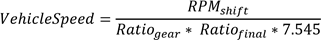
These maps have inputs of Accel Pedal in % and outputs of road speed in Km/h, defining the speed at which the upshift or downshift is triggered depending on the accel pedal position. These can be approximated to an RPM using the following formula:

Alternatively the required speed can be calculated from the target shift RPM by rearranging the above formula:
| Gear | Stock Ratio | Km/h Per 1000RPM |
|---|---|---|
1 | 4.06 | 8.823 |
2 | 2.3 | 15.574 |
3 | 1.59 | 22.529 |
4 | 1.25 | 28.657 |
5 | 1 | 35.821 |
6 | 0.797 | 44.945 |
The Stock final drive ratio is 3.7 and the stock gear ratios are listed below with values for km/h per 1000rpm. It should be noted that due to the delay in an upshift completing you should use a vehicle speed that corresponds to a lower RPM than your ultimate target, this is more important in lower gears when the RPM rate will be higher. And due to clutch slip these values are not always 100% accurate.
The below 2 charts show the difference between Normal and P3 ASC shift schedules across all gears (JF04)
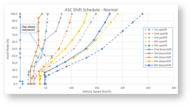
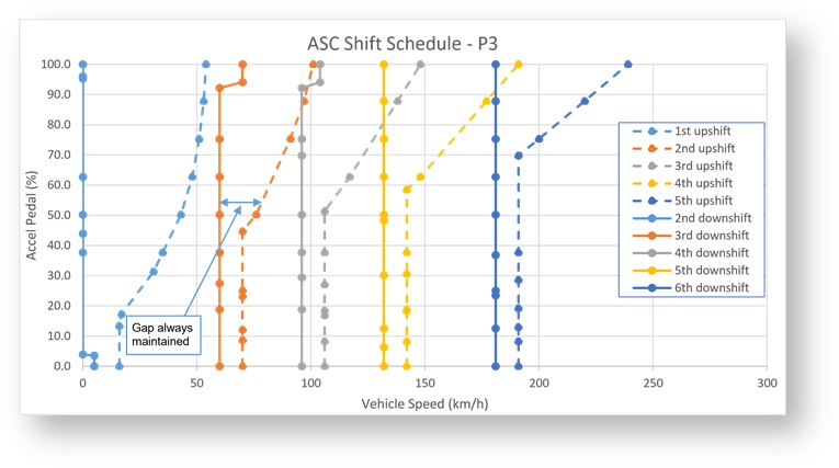
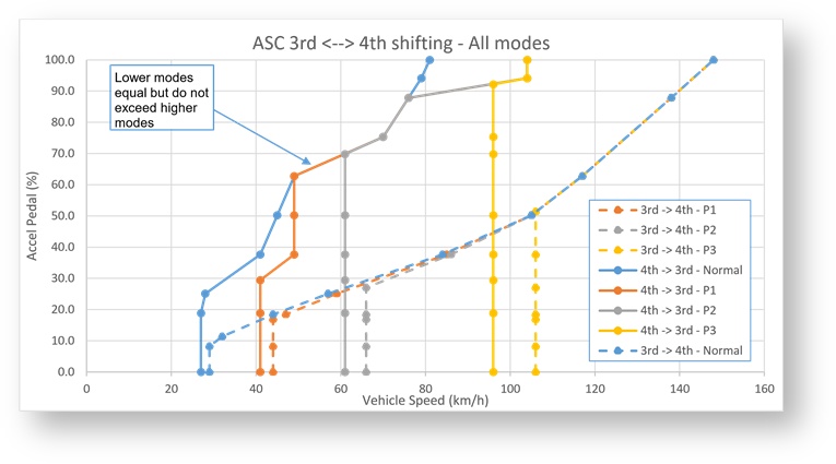
This chart shows all of the shifting options between 3rd and 4th gear in modes N through P3
Rules for shift point values
When editing shift schedules it’s important to follow some basic rules to avoid unexpected results and seemingly random shifts.
For any given group (N to P3) downshift speed (gear) =< upshift speed (gear-1) Otherwise a downshift will immediately trigger an upshift.
For upshift and downshift, at any given Accel %, speed in N =< P1 =< P2 =< P3 Otherwise driving harder will force upshifts and downshifts at lower RPM.
Notes:
- Putting the transmission in Race mode will instantly raise the shift schedule to P1, although with gentle driving it can drop back down to Normal.
- The data values in the shift maps of 1mb TCM roms is limited to 255km/h due to being 8bit values, 1.5mb
ROMs do not have this limitation (max value is 1310.7). For auto upshifting at higher speeds than 255km/h (fast standing mile cars for example) we recommend using a manual shifting mode and adjusting the shift limits as outlined in the following section.
- When accelerating hard, a high power GTR will continue to accelerate and the RPM rise as the shift is completed (please refer to “Understanding the Upshift Sequence”). As a result in low gears the shift speed is set lower than expected to ensure the RPM doesn't hit the limiter by the time the shift has completed, which can easily take 0.5s in low gears (total time from trigger to next gear clutch fully engages).
Map List
Shift Limits (Auto Upshift in Manual Mode)
You can now have full control of when the TCM chooses to shift in all modes including Manual and Manual Race with the inclusion of shift limit maps.
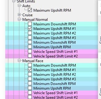
Depending on the mode or conditions there are limits on when shifts can happen. For example to prevent 5th gear being selected in manual mode at 7000rpm in 6th gear to stop over revving, but also a minimum to prevent 3rd gear being selected at too low and RPM that would stall the engine. These maps are all in RPM, and for "Manual Mode" and "Manual Race Mode" there are separate limits for minimum and maximum upshift and downshift. There are also additional limits for when using cruise control which stops shifting at high RPM despite ASC shift schedules.
As you can see from the following screenshot the limit for auto upshifting in Manual Race mode is 10000RPM which is which to intents and purposes it is disabled. Auto mode also has the same 10000RPM limits because the ASC shift schedules should take care of the shifting decision.
While cruise control is active there are lower shift limits, these are not used if you are increasing your set speed using the cruise control switches, but are used when the ECM is maintaining a steady set cruise speed.
Check the Help text for each map individually to check the engine RPM type being use, there are 2 options:
- Current RPM = RPM at the moment you want to trigger the shift in the gear that you currently in.
- Post Shift predicted RPM = Calculated RPM in the gear that will be shifted to AFTER the shift is complete.
For Maximum Upshift and Minimum Downshift the RPM is "Current RPM".
For Minimum Upshift and Maximum Downshift the RPM is "Post Shift Predicted RPM" For each map, the help text describes what type the RPM values are.
Example of Current RPM limit
In the 80B0A ROM the Maximum Upshift RPM in "Manual Mode" for 2nd gear is 6674rpm. This means that if the driver doesn't pull the paddle to trigger, an upshift the TCM will automatically trigger an upshift in 2nd gear at 6674rpm. Note that in low gears the limits are deliberately low to avoid hitting the limiter due to the time it take for a shift to ctually happen while the RPM is rapidly increasing.
Example of Post Shift Predicted RPM limit
In the 80B0A ROM the Maximum Downshift RPM in "Manual Normal" for 5th gear is 6965rpm. This means that when downshifting from 6th to 5th the TCM will not allow the downshift to happen until it calculates the RPM after the shift in 5th gear will be less than 6965rpm, this is why the 6th-5th downshift limit appears in the row for 5th gear.
Map List
Launch Control
For more information refer to the GT-R Factory Launch Control
ROM Compatibility
There are 3 main groups of TCM ROM:
- Gen 1 JF and JW series ROMs – 1Mb in size
- Gen 2 KB and KJ series ROMs – 1Mb in size
- Gen 2 38, 62, 80 and 89 series ROMs – 1.5Mb in size ROM FILE SIZE MUST MATCH THE TCM SIZE!!
- A 1.5mb ROM cannot be programmed into a 1mb TCM.
- A 1mb ROM cannot be programmed into a 1.5mb TCM.
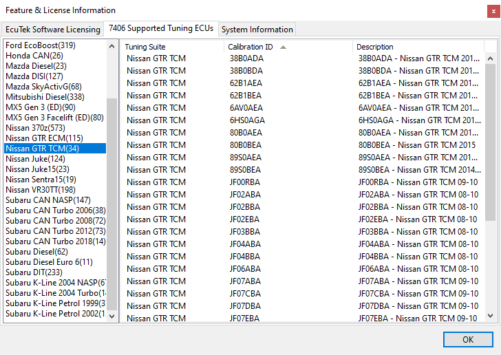
To see the latest version ECM ROM that should be chosen for your region, go to Feature & Licence Information under the Help menu, and the select the Supported Tuning ECUs tab:
Suggested Roms
1Mb TCM
We recommend that the LC5 TCM ROM 32085-KJ10BDA-enc.bin is used in all 1mb TCMs (even if the ECM has not or will not been programmed with ProECU). We also recommend adding the latest version 5 RaceROM (v19472 or later) to enable the sending of extra info to the ECM and/or allowing for the Mapswitch mode to be displayed on the tacho.For
It’s recommended that the latest Engine ECU ROM is also used in conjunction with the LC4-LC5 TCM code. The KJ ECM code is better suited and more compatible for the later Gen 2 TCM code versions (LC4-5).
For Gen 1 models the latest ECM code version would be the JW series ECU ROM.
Some Examples are shown below for Gen 1 GTR:
| Factory ECM Rom | Suggested ECM ROM | Factory TCM ROM | Suggested TCM ROM |
|---|---|---|---|
| JF51A Euro | JW93A Euro | JF04BBA | KJ10BDA |
| JF04A Japan | JW90A Japan | JF02BBA | KJ10BDA |
| JF30A USA | JW92A USA | JF09DBA | KJ10BDA |
1.5Mb TCM
The latest 2013 onwards TCMs with the 1.5mb ROMs all provide smooth shifting and launch control, and there isn’t much to choose between them. Like the earlier TCMs we recommend adding the latest V5 RaceROM (v19472 or later).
The "Nismo" ROM
The ROM referred to when tuners mention the “Nismo” rom is in fact 32085-89S0BEA-enc.bin and is automatically downloaded via EcuTek Update by ProECU. It is a 1.5Mb rom and cannot be programmed into a 1mb TCM! Some development work is in progress to identify more of the subtle changes between the 89S0BEA ROM and earlier 1.5Mb ROMs so they can be imported to the 1Mb ROMs. This may be included in a later release of ProECU but until it is announced EcuTek cannot help with more specific enquiries relating to the 89SOBEA ROM.
2008 JDM TCM Issues
Some very early Gen 1 JDM region models may seem incompatible with later LC2 to LC5 TCM ROMs.
The CEL light is shown after programming but no DTCs are stored.
Programming the original LC1 TCM ROM version again will solve the DTC issue but it doesn’t help us improve the TCM software.
It is possible to use the far superior LC5 ROM in these ECU by ensuring the ECM and TCM DTCs are cleared correctly and the ECM is Reset after programming the later TCM software.
The READ and CLEAR DTCs sequence will need to be repeated 2 or 3 times before the TCM DTCs are successfully cleared, so persevere and eventually the TCM CEL will clear.
You can carry out the TCM Auto Learn sequence followed by manual
GTR TCM FAQ
Which TCM ROM should I use ?
We recommend that the LC5 TCM called ‘32085-KJ10BDA-enc.bin ‘ is used in all 1mb TCMs (even if the ECM has not or will not been programmed with ProECU). For 1.5mb TCMs the latest rom for your region is usually a safe bet. If you intend to use Tacho needle display or Valet mode on the ECM then adding the latest RaceROM is essential.
The car is not smooth on gear changes.
Ensure you have the LC5 TCM ROM installed and use the latest RRFF phase 5 (19464) or newer installed, the phase 5 provides incredible smoothness and driveability. Also ensure on Gen 1 cars that you are running the JW or KB series ROM.
The clutches slip on full load
It’s critical that the Fuel Trims are within +/-10% so that the Engine Torque value sent to the TCM is accurate. If it’s too low the clutches will slip, watch the Clutch Slip logging parameter in the TCM ROM. Make a log of the TCM during a full load run, the maximum clutch pressure is normally 16.5 to 17.2bar, the clutch seals cannot hold more that this during our testing. See the ECM Tuning Guide for advice on adjusting the Torque Actual map to avoid the clutches slipping.
Why doesn’t Race ROM Launch Control work?
Ensure coolant temp is over 70 deg C, ensure your TCM ROM has RRLC enabled in the mode you are using. Also see the Launch Control section for more help.
The car doesn’t launch well
If the car bogs on launch or just after launch then make a TCM Learning sequence then adjust the clutch capacity and touch points as per the Special Tools section later in the manual. Too much clearances on the touch points can cause this.
I cannot get the Idle Learning or Gearbox Learning to work
Ensure the oil temps are hot, if bigger MAF tubes are fitted then try adding plus 5% to the MAF scale in the idle region, there is a minimum airflow g/sec required for the learning sequence to commence.
I get an error message trying to program the ECM or TCM
The engine should not be running and in PARK, also ensure headlights and interior fan blower are off, see the ECU programming section for further advise.
I get Torque error DTCs when pulling away or driving
- Ensure you are running RRFF phase 3 or newer.
- Ensure the K Factor values are stock (as K Factor will distort the engine torque values given to the TCM). See the previous idle stability questions as well.
- Some aftermarket BOV with strong springs can cause this.
- Try enabling Speed Density as a test to help you understand the problem.
EcuTek ProECU tuning tools tools should only be used by experienced tuners who understand the product and engine calibration.
If you do not fully understand this product then you WILL damage your engine, ECU or your vehicle.
Please ensure you fully read all EcuTek manuals BEFORE attempting to use ProECU with your laptop or your vehicle.
Use with extreme caution and understanding at all times, if in doubt then do not proceed.
EcuTek accepts no responsibility for any damage to the engine, ECU or any part of the vehicle that results directly or indirectly from using the product.
** If you are in any doubt that you do NOT have the experienced required to use this product then you should NOT USE IT **
Retail customers
** If you have any doubt that you do NOT have the experienced required to use this product then you should NOT USE IT, you should simply contact your EcuTek Master Tuner shown clearly on the top of your Programming Kit or visit your preferred tuning shop to have a professional tuner to use it for you **