GT-R RaceROM Speed Density Guide
- Brandyn Mowat
How to set up Speed Density
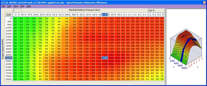
.The SD VE map is against Engine Speed (RPM) and Manifold Relative Pressure (Bar). The values in the map are volumetric efficiency (VE) %. The older RRFF SD Map had Mass Airflow values in the SD map but the latest RRFF now uses a superior VE based SD calculation which we will cover here.
When the SD map is active it simply replaces the current Mass Airflow (g/sec) reading that would normally come from the MAF sensor, therefore ALL load calculations are not affected by the MAF sensor at all. When the SD map is correctly calibrated there is little difference from running on MAF and the SD VE map works in this fashion:
Increasing the SD values will make Engine Load higher therefore retarding the Ignition and increasing the Injection volume amount therefore making the AFR richer. While Reducing the SD values will make Engine Load lower, therefore advancing the Ignition and reducing the Injection volume amount therefore making the AFR leaner. The Speed Density Volumetric Efficiency map utilises the Plenum based MAP sensor to calculate SD. It does NOT use the pre throttle Boost Pressure sensors. The stock MAP sensors can read to 2.7 bar absolute (39.5 psi absolute), any pressure over 2.72 bar absolute will need a 4bar MAP sensor fitting.
The default SD map has been calibrated for a stock vehicle, the VE based calculation will be seriously affected by any fundamental change in VE (like fitting larger turbochargers or changing the camshafts).
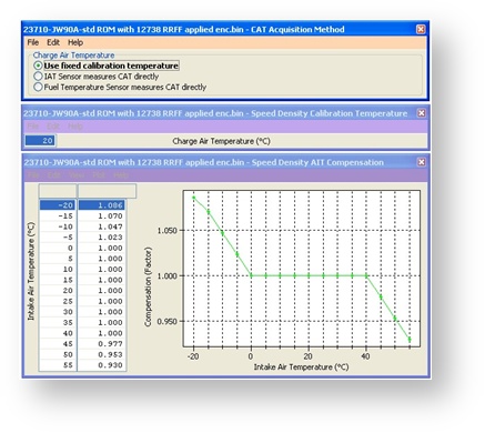
Charge Air Temp (CAT) also plays a critical part in the VE calculation. Unfortunately Nissan did NOT equip the vehicles with a charge air temp sensor from the factory so if you aren't adding one in, we have to assume a fixed temperature and then make a calibrated compensation based against Intake Air Temp.
No air temp sensor fitted in the charge pipe
The Speed Density Temp Compensation map will adjust the SD VE calculation based on the current IAT, therefore attempting to calculate the true air density by calibration.
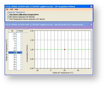
Intake Air temp sensor fitted in the charge pipe
If the Air Intake Temp sensor (AIT) has been placed in the charge pipe and the IAT is measuring true CAT (after the turbo and intercooler) then we do NOT need to use the ‘Speed Density Temp Compensation’ map (as VE calculation is including true CAT), in this situation we need to select the CAT Acquisition Method of ‘IAT sensor measures the CAT directly’ option. We also need to set the values in the Speed Density Temp Compensation to 1 as we are not ‘guessing’ the CAT anymore.
Removal of MAF sensor (optional)
It is expected that this feature will be used in applications where you wish to replace the MAF sensors with a custom intake. If you remove the MAF sensors, you must go to the Enabled Diagnostic Trouble Codes map and disable the error relating to Mass Airflow Sensors. If you do not disable these codes then the ECU will detect a “Mass Airflow sensor failure” and use its fallback processing instead of the Speed Density feature.
The Nissan Intake Air Temperature sensor is built into one of the MAF sensors. You should provide a temperature sensor within your replacement intake or the intake manifold. If this is not possible, disable the error codes relating to IAT sensor so that the ECU does not detect that the IAT sensor has been removed. Then update all maps that use IAT as an input to return a sensible output value regardless of the IAT input value.
Map List
Live Data
- Dig: Speed Density – Digital flag, set to 1 when Speed Density is Active
- Engine Load Absolute – Engine load calculated by the speed density strategy
- Mass Airflow Estimated (SD) – The mass airflow in g/s as calculated by speed density strategy
- SD Volumetric Efficiency – The VE used by the speed density strategy
How to set up Hybrid Speed Density
Hybrid SD mode options
RaceROM’s powerful Hybrid Speed Density allows the Load Input to be switched between MAF and SD as required. The transition can be ‘MAF then SD’ or ‘SD then MAF’.
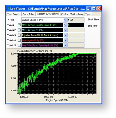
Hybrid SD is a great solution if your MAF volts are hitting 5volts at a higher RPM.
In this situation you can run the superior MAF load input for most of the time then switch to SD when the MAF is nearing 5 volts.
In this example to the left we would switch to SD around 5500rpm where the MAF is at 4.90volts and just before the MAF’s hit 5volts.
Remember to check the MAF volts on both Bank #1 and Bank #2 as one MAF might flow more than the other.
The parameter used in order to shift the ECM Strategy from MAF to SD can be any one, or a combination of:
- Engine Speed (RPM)
- MAP (Bar)
- Mass Airflow (g/sec)
In the previous example we would specify that past 5500rpm we switch to SD but we can also say that boost pressure has to be over 1.2bar as well, this would prevent the SD from ever working below 1.2bar and below 5500rpm.
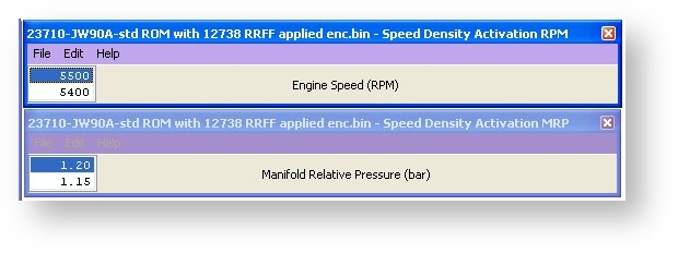
In this example the engine will be running on MAF at Idle, low load and it will stay on MAF until 5500rpm AND the boost exceeds 1.2bar relative. As soon as the RPM drops BELOW 5400rpm or the Boost drops BELOW 1.15bar then the ECU will switch back to MAF.
In order to get a smooth transition when swapping between ‘MAF and SD’ or ‘between SD and MAF’ we want to make sure that the MAF and SD maps read very similar airflow levels at the switching point so that the car isn't immediately seeing a large adjustment of fuel/ignition timing etc. One major point to make this easier is that ProECU can log the output of the MAF sensors even if they are not used by the ECU (i.e. the ECU is running on SD not MAF).
To calibrate for a hybrid transition we need to Enable SD earlier than the switch point, if the switch point is 5500rpm then enable SD over 4000rpm. Even though the ECU is using SD past 4000rpm the MAF can still be logged, now we need to log the following three parameters.
- Mass Airflow Absolute (MAF) (g/s) – The mass airflow reading from the MAF sensor
- Mass Airflow Absolute (SD) (g/s) – The mass airflow calculation from the SD map
- SD Volumetric Efficiency (%) – The output of the SD map
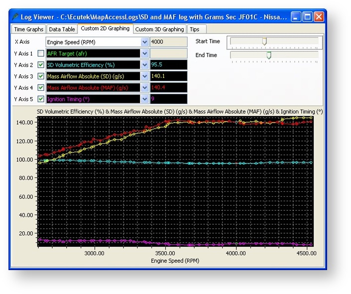
The log file shot below shows the ECU running on SD. As shown in that log, the ECU is currently running on SD, we know this because the SD VE shows 95% and Mass Airflow readings for MAF and SD are different. If the ECU was using MAF the SD VE reading would be 0% and the Mass Airflow readings would be the same. The Mass Airflow readings for MAF and SD are very close between 3500 and 4500rpm so it would be a very smooth transition to swap from MAF to SD (or SD to MAF) at any RPM shown below. The Mass Airflow is from our SD map, the MAF sensor reading is also logged but is not used by the ECU.
Here is an example of a Good Hybrid SD transition
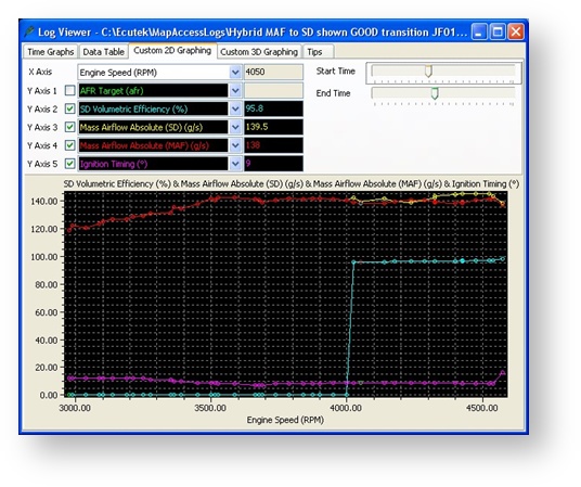
At 4000rpm the ECU swaps to SD and the SD VE value moves from 0 to 95.8%, the Mass Airflow reading comes from SD map and not the MAF sensor (but they read very similar values). This is a great example and the switch point from MAF to MAP will be a smooth transition.
Here is a BAD Hybrid SD transition
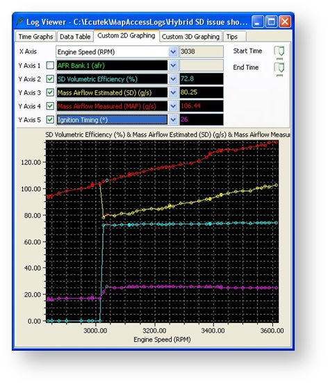
This is BAD hybrid tuning and the car even had clutch slip problems during transition. In this example the SD is switched ON at 3000rpm. You can see the SD VE parameter go from 0% to 72.8% when SD activates and SD now provides the ECU with the Mass Airflow input value for its load calculations. Additionally you're able to see that the Mass Airflow calculated from the SD VE maps (shown in yellow) suddenly drops from 106 grams/s to 80 grams/s but the Mass Airflow as shown by the MAF sensors (in red) continue to read a more sensible and true Mass Airflow. In this case the SD map has been poorly calibrated!
As the SD is enabled the Mass Airflow drops and engine load drops drastically and Ignition timing jumps from 17 to 26 degrees. The Fuel Trim also went to 125% to add enough fuel. In order to fix this issue, the SD map needed increasing from 76% to 98%. From this we can see first hand that to make smooth transitions it’s critical to make sure MAF and SD read close before and after the transition swap.
An additional thing to keep in mind is that you'll need the Fuel Trims correct running on MAF, if not then adjust the MAF scaling until they are correct. Once you're done, enable SD and ensure the Fuel Trims are correct and if not then adjust the SD map. Then you can set the conditions to switch as you wish! As you can enable SD in any of the 4 map switch modes you could use MAF in MODE 1 and SD in MODE 2 to get a back to back result in the same run/log without needing to reflash the car.
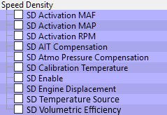
Maps
SD Activation MAF
Hysteresis is achieved using two separate values for activation and deactivation. The upper value (0 by default) is the MAF in g/s over which SD will become active, the lower value (0 by default) is the MAF in g/s below which SD will become inactive.

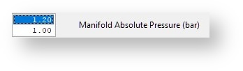
SD Activation MAP
Hysteresis is achieved using two separate values for activation and deactivation. The upper value (0 by default) is the MAP in bar over which SD will become active, the lower value (0 by default) is the MAP in bar below which SD will become inactive.
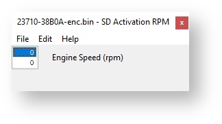
SD Activation RPM
Hysteresis is achieved using two separate values for activation and deactivation. The upper value (0 by default) is the engine speed in RPM over which SD will become active, the lower value (0 by default) is the engine speed in RPM below which SD will become inactive.
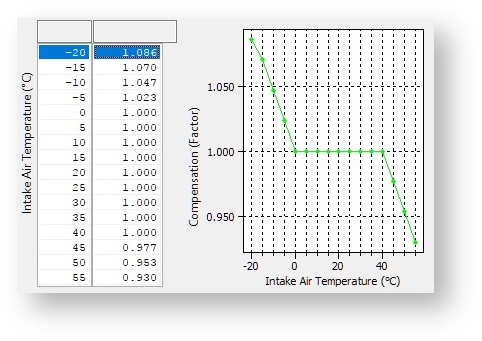
SD AIT Compensation
If the SD Temperature Source is set to Use fixed calibration temperature this map can be used to make adjustments to the calculated mass airflow based in Intake Air Temperature. It can be used in situations where SD is required on an otherwise standard car to deal with MAF limits, and a dedicated charge air temperature measurement solution is not in place.This map is ignored if either of the direct temperature measurement sources are used.
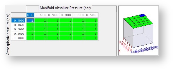
SD Atmo Pressure Compensation
This can be used to compensate for the changes in VE typically experienced at high altitude and low atmospheric pressure. The values will multiply the VE from the SD VE map.
SD Calibration Temperature
This is the charge air temperature assumed by the Speed Density strategy if SD Temperature Source is set to Use fixed calibration temperature.

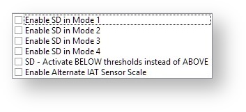
SD Enable
An overall enable of the Speed Density strategy on a per mapswitch mode basis. It also includes options to use the activations thresholds as maximums in cases were SD is employed in low load conditions, and to activate the alternative IAT sensor scaling in Sensors » Intake Air Temperature » Alternative IAT Scale.
SD Engine Displacement
The engine displacement is a key part of calculating the rate of air consumption, increasing or decreasing this value will proportionally increase or decrease the resulting mass airflow. Ensure this is changed to match the capacity of non-standard engine builds.

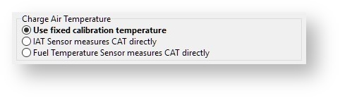
SD Temperature Source
This is used to select Speed Density strategy handles Charge Air Temperature for air density compensations. If Use fixed calibration temperature is selected, temperature is assumed to be constant at the level set in SD Calibration Temperature and the mass airflow is corrected as per the multiplier in SD AIT Compensation.
If IAT Sensor measured CAT directly is selected, the temperature input from Input Air Temperature sensor (normally located in the MAF sensor) is used as part of the ideal gas law calculation to estimate air density and SD IAT Compensation is ignored.
Fuel Temperature Sensor measured CAT directly can be selected if a dedicated Charge Air Temperature sensor is wired into the fuel temperature input (a useful option for cars that don’t have a fuel temperature sensor as standard). The output from the sensor is then used in the ideal gas law calculation to estimate air density and SD IAT Compensation is ignored.
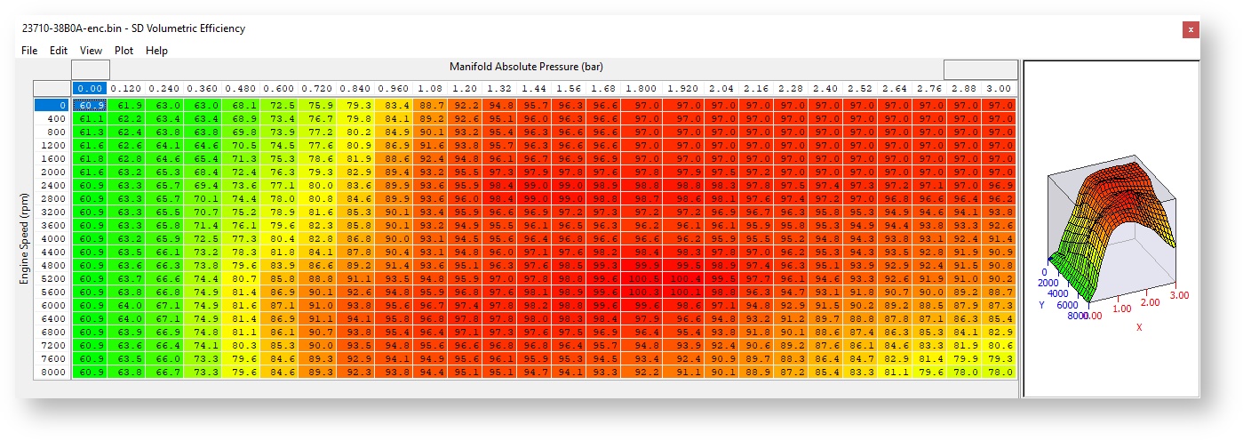
SD Volumetric Efficiency
Only a snippet of this 26x21 cell map shown above. It is used to correct the volumetric air flow of the engine based on manifold absolute pressure and engine speed. The default map is good enough run a mostly stock car in full time SD and should be a good based for custom tuning.
It would not be expected for the values in this table to exceed 105%, if you find yourself using values much higher than this, it’s the sure sign of other problems such as poorly calibrated injectors or insufficient fuel flow. A badly calibrated VE map will lead to incorrect load estimation leading to erroneous torque values being sent to the TCM and poor shifting can result.
EcuTek ProECU tuning tools tools should only be used by experienced tuners who understand the product and engine calibration.
If you do not fully understand this product then you WILL damage your engine, ECU or your vehicle.
Please ensure you fully read all EcuTek manuals BEFORE attempting to use ProECU with your laptop or your vehicle.
Use with extreme caution and understanding at all times, if in doubt then do not proceed.
EcuTek accepts no responsibility for any damage to the engine, ECU or any part of the vehicle that results directly or indirectly from using the product.
** If you are in any doubt that you do NOT have the experienced required to use this product then you should NOT USE IT **
Retail customers
** If you have any doubt that you do NOT have the experienced required to use this product then you should NOT USE IT, you should simply contact your EcuTek Master Tuner shown clearly on the top of your Programming Kit or visit your preferred tuning shop to have a professional tuner to use it for you **